1. Introduction
The global warming issue is significantly increasing, the Arctic ice layer is gradually melting, and, hence, the sea level is rising. The reason for this is that humankind has no restraint in the use of energy, and the number of cars in the world grows year by year. Improving the efficiency of internal combustion engines has become one of the mainstreams to overcome this problem. There are many ways to improve the efficiency of internal combustion engines. Among them, variable valve timing (VVT) and variable valve lift (VVL) techniques are effective options to improve engine efficiency [
1]. Especially, the intake for a camless engine purely depends on valve actuation. The energy consumption of internal combustion engines can be reduced by using active valve trains such as electromagnetic, electronic–hydraulic, electronic motor valve trains, etc. [
2]. These can reduce engine consumption by 15% and reduce exhaust emissions by 20%. Several automobile firms have presented their devices with their technologies. The electro-mechanical-based VANUS from BMW [
3], the hydraulic-based VTEC from Honda [
4], Shiao’s magnetorheological valve train [
5], and the electro-hydraulic-based VarioCam from Porche [
6] are successful examples.
Among the existing active valve trains, the electro-mechanical valve drive (EMVD) [
7,
8] is the conventional one, which gives variable valve actuation with an electrical motor and mechanical linkage. This linkage uses nonlinear conversion to convert the rotary motion into reciprocating motion, so that the valve can be opened and closed, and the engine can achieve variable valve timing during operation to improve engine efficiency. However, due to the complexity of the mechanism and the larger size of the motor, the size of the engine will increase. Moreover, the motor needs to be continuously supplied with power, which requires high total energy consumption.
Second, the electro-hydraulic valve actuator [
9,
10] mechanism uses a servo-motor-based switch to control the hydraulic circuit of the valve mechanism. This switch-controlled hydraulic circuit can precisely control the opening and closing of the valve, so that the engine can achieve variable valve timing and variable valve lift when the engine is running. This effectively improves engine efficiency. However, the overall mechanism is more complicated: it still needs to cooperate with the hydraulic system, and the servo valve is continuously energized, which requires high energy consumption, so there are concerns about leakage of the hydraulic system. Moreover, the electronic control has a faster response than the electric-hydraulic or electro-mechanical control. Then, electronically controllable electromagnetic valves (EMV) [
11,
12,
13] were introduced for valve actuation. They are constructed with a set of electromagnet coils on the upper and lower sides of the armature. The coils can be energized to generate magnetic force, and the armature in the middle is attracted to move up and down by electromagnetism, to control the opening and closing of the valve, so that the engine can achieve variable valve lift and timing actively during different loads and speed conditions. The EMV has advantages such as compact design, accurate control, and quick response. However, like other active valve systems, EMV also consumes energy for the actuation of the electromagnets.
Therefore, a design of permanent magnet-based EMV has been developed to reduce the energy consumption of the EMV. In addition to retaining the original electromagnet, these valve mechanisms [
14,
15] also have permanent magnets (PM), so that this PM force can hold the valve during the valve closed position. Lee [
16] suggested a new compact electromagnetic engine valve, with the design of dual permanent magnets, and performed software analysis and optimization on the mechanism. It relies on the magneto force of the permanent magnet to keep the valve closed. To release the armature, an electromagnet must be used to generate a reverse magnetic circuit to eliminate the magnetic force of the permanent magnet. However, the permanent magnet composite electronic valve will cause the problem of permanent magnet demagnetization under long-term operation.
Aslam [
17] developed a hybrid electronic valve with a special design of inner and outer double-layer coils in the mechanism design. The advantage is that when the armature is attracted, it can have a better attraction force, lower energy consumption, and lower coil inductance. However, the demagnetization problem occurs under the long-term operation of the electronic valve. The compound electronic valve proposed by Waindok [
18] is similar to the compound electronic valve, but the control and driving method is different, and the magnetic circuit direction is also different. The operation mode of this electronic valve is that when the armature moves to one vertex, it must be connected to the other vertex. The coil’s current causes the armature to attract and move to this apex, but the disadvantage is that when the electronic valve is operating, a larger current must be passed to make the electronic valve operate. Paden proposed a new voice-coil-type electronic valve [
19]. The design of this mechanism stands out from other electronic valves. The sound coil mechanism is used on the electronic valve. When the voice coil electronic valve is not in operation, the valve is half-open, and the unique current drive control method must be used when operating. The air valve starts to move up and down to the apex, but the disadvantage is that the electronic valve must be operated in advance, and the current must be continuously supplied during the operation to make the voice coil electronic valve work normally.
Generally, composite electronic valves mostly use reverse magnetic circuits to offset the magnetic force of the PM, so that the armature is released. However, this reverse magnetic circuit affects the longtime magnetic property of the PM: it weakens the magnetic force or leads to permanent demagnetization. Therefore, Shiao [
20] introduced the guided magnetic circuit to control the PMEMV. This mechanism design is different from other PM composite electronic valves. It uses guided magnetic circuit channels to guide the magnetic circuit of the PMs, so that the armature is released to achieve the operation of opening and closing the valve. It will effectively improve the effect of the permanent magnets on demagnetization. However, this design has a problem during the armature travel from one side magnet to the other. The armature cannot travel to the permanent magnet attraction range with the available spring force. This paper aims to overcome the mentioned problem of the hybrid PMEMV model designed by Shiao [
21,
22]. This study introduces an effective and smart magnetic circuit control strategy for the PMEMV to attain variable valve actuation. Hence, the hybrid PMEMV, which consumes less energy, can achieve the release and attraction of the armature accurately and completely. A control signal with a catching pulse and releasing pulse is introduced to the electromagnetic guiding coil, to give extra attraction force to the armature of the valve. The magnetic simulations are performed for the proposed valve train to analyze the direction of the magnetic circuit during the valve actuation and are experimentally validated to understand the real-time performance.
2. Structure and Working of the New Hybrid PMEMV
The proposed EMV is to be placed in the cylinder head to control the intake and exhaust of the engine.
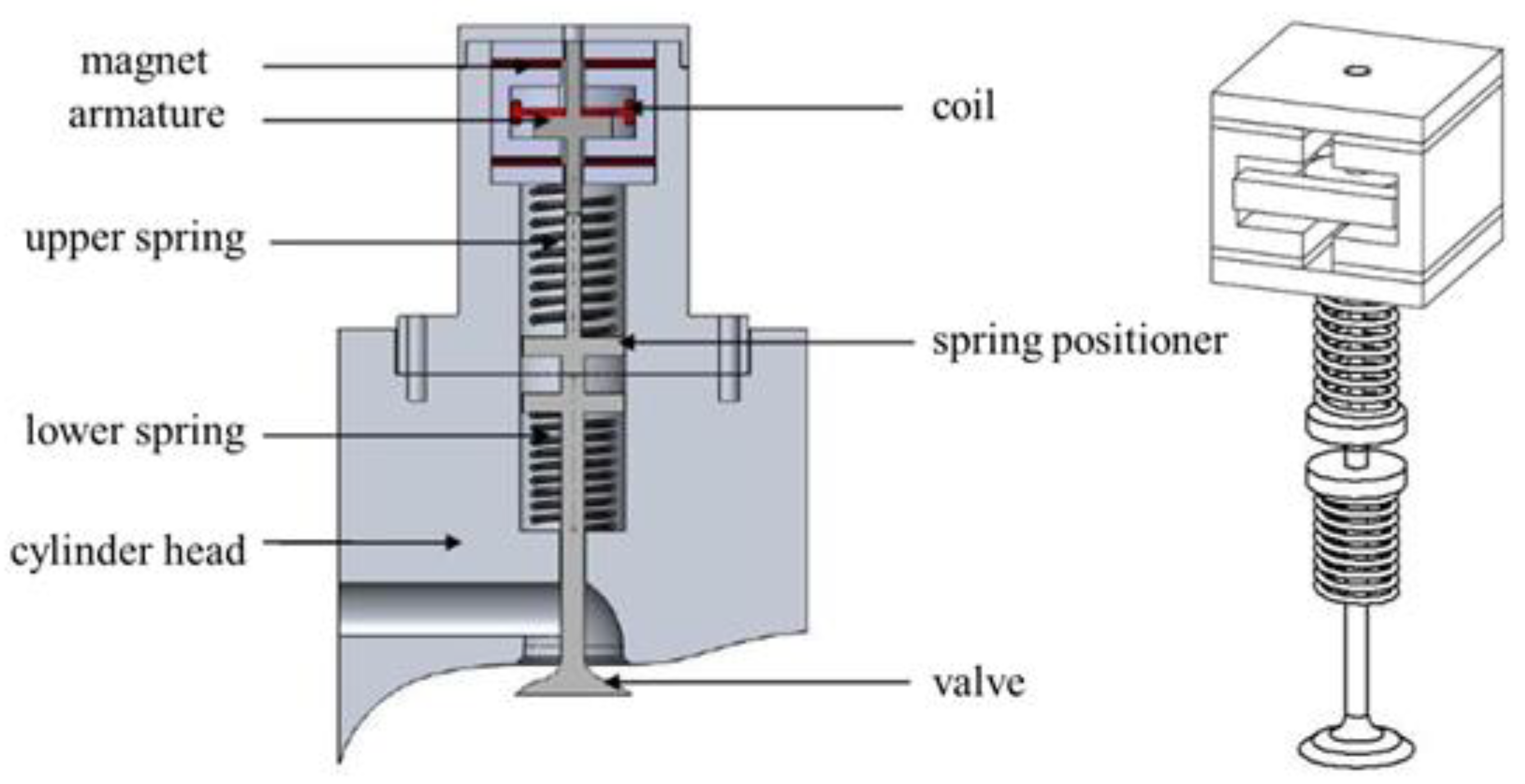
Figure 1 shows the structure of the electronic valve that includes the springs, spring positioner, armature, permanent magnets, guiding coil, and valve. The armature in the valve body can freely move in the vertical direction. The magnetic passages on both sides of the electronic valve are individually coiled to generate electromagnetic force. The upper permanent magnets (UPM) and lower permanent magnets (LPM) are placed at the upper and lower sides of the armature. When the guiding coil is not energized, the armature is attracted to either the upper or lower magnets. When the guiding coil is energized, the armature will move away from the existing position, due to the spring force, and then be attracted to another magnet side. The opening and closing of the air valve will be achieved. With this electronic valve mechanism, the total stroke of the valve from closing to opening is 8 mm.
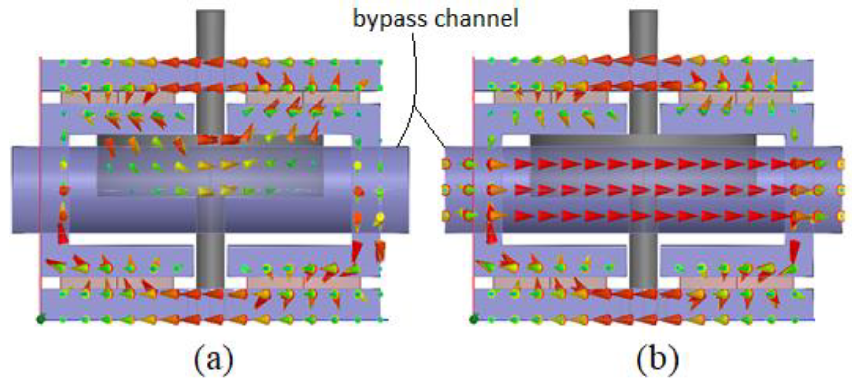
Figure 2 shows the flux path during conditions when the guiding coil is energized and not energized. The magnetic flux of the PM travels via armature when the guiding coil is not energized, traveling via the bypass channel.
The working principle of the hybrid PMEMV is shown in
Figure 3. The direction of the arrow is the direction of the magnetic circuit, and the thickness of the arrow signifies the magnitude of the magnetic force. Initially, during the zero-current condition, the direction of the upper magnetic circuit passes through the armature, as shown in
Figure 3a. It means, that UPM exhibits a magnetic attraction force on the armature, which is higher than the spring force. Hence, the valve sustains, in its closing position, until the electromagnetic (EM) field is activated. When the EM circuit (guiding coil) is energized, it diverts this magnetic flux from the armature to the bypass channel, as shown in
Figure 3b,c. Therefore, the attraction force between the armature and the UPM is dropped, then the spring force of the lower spring mechanism is used to make the armature leave the UPM, and the air valve opening starts at this time. Next, the armature starts moving on the opposite side of the existing position due to spring force. As shown in
Figure 3d, when the armature is affected by the spring force of the spring mechanism and leaves the UPM and reaches the LPM, the armature is attracted by the permanent magnet at the LPM, and the air valve is now fully opened. The hybrid electronic valve is a symmetrical design. Therefore, the direction of the magnetic circuit during the movement of the armature from the lower apex to the upper apex is also followed in a similar process, as shown in
Figure 3d–f.
The operation of the electronic valve must be controlled by precise current pulses, to drive the armature to move effectively and achieve the opening and closing of the electronic valve.
Figure 4 shows the electronic valve operation cycle and the release current actuation timing.
However, the above pulse signal is not effectively working due to the inadequate magnetic force of the PMs.
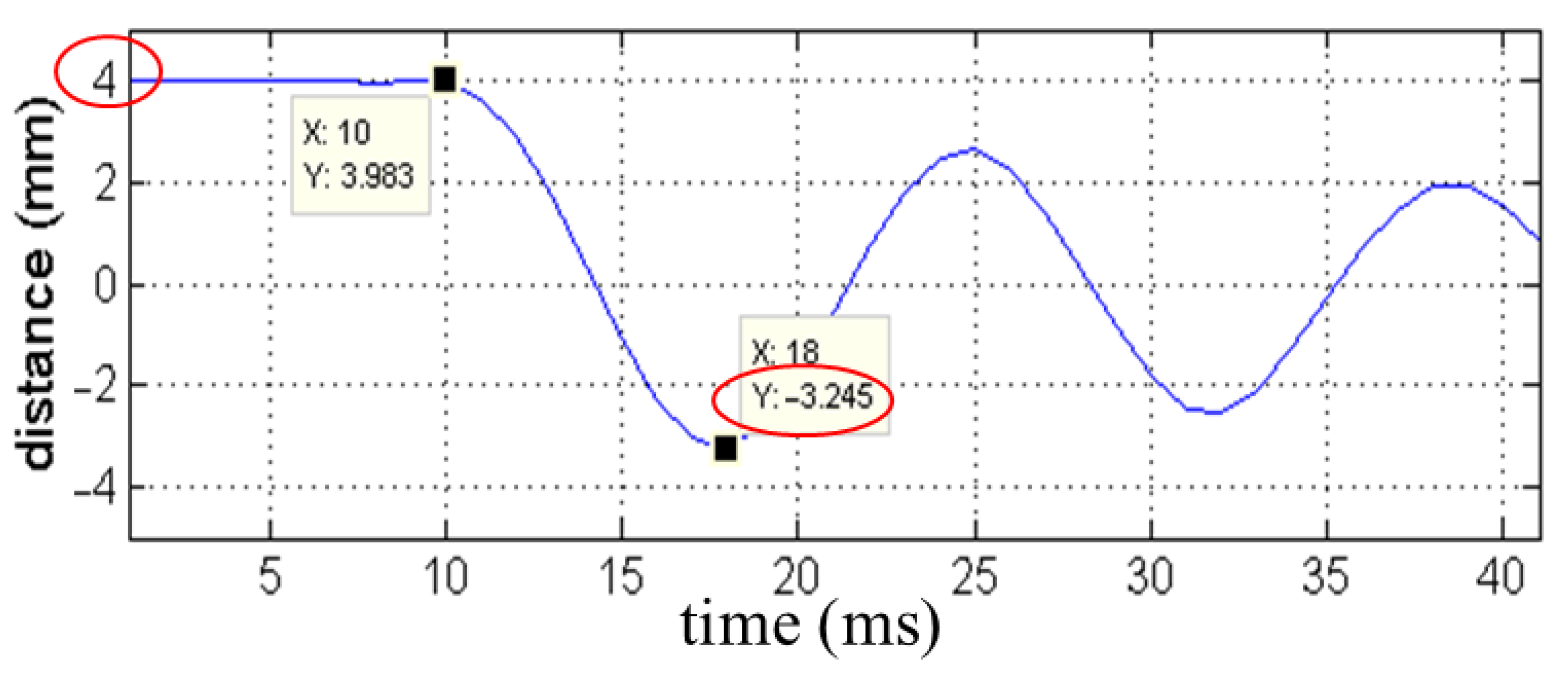
Figure 5 shows the experimental results of the proposed guided EM valve displacement (mm) with the above control signal. When the current is given to the coil, the upper vertex permanent magnet attraction force on the armature is decreased, and then the armature is released downward due to the spring force. However, when it approached the lower vertex of −3.245 mm, the armature has not reached the permanent magnet attraction range and is pulled back by the spring force. Hence, it was not successfully attracted by the bottom vertex, due to the 0.755 mm stroke shortage. Eventually, the valve opening was inaccurate and incomplete. Therefore, the following section discusses the better control signal for PMEMV, to achieve complete valve opening and closing.
3. Improvement of the Control Approach for PMEM Valve
Although the attachment of additional mechanisms can solve the problem mentioned in the previous section, it will increase the volume and weight of the valve. Therefore, this study focused on the control signal but not on adding additional mechanisms. To enable the hybrid PMEMV to operate effectively and completely, this paper proposed the application of an additional pulse to give external force, to make up for the lack of stroke of the hybrid EMV.
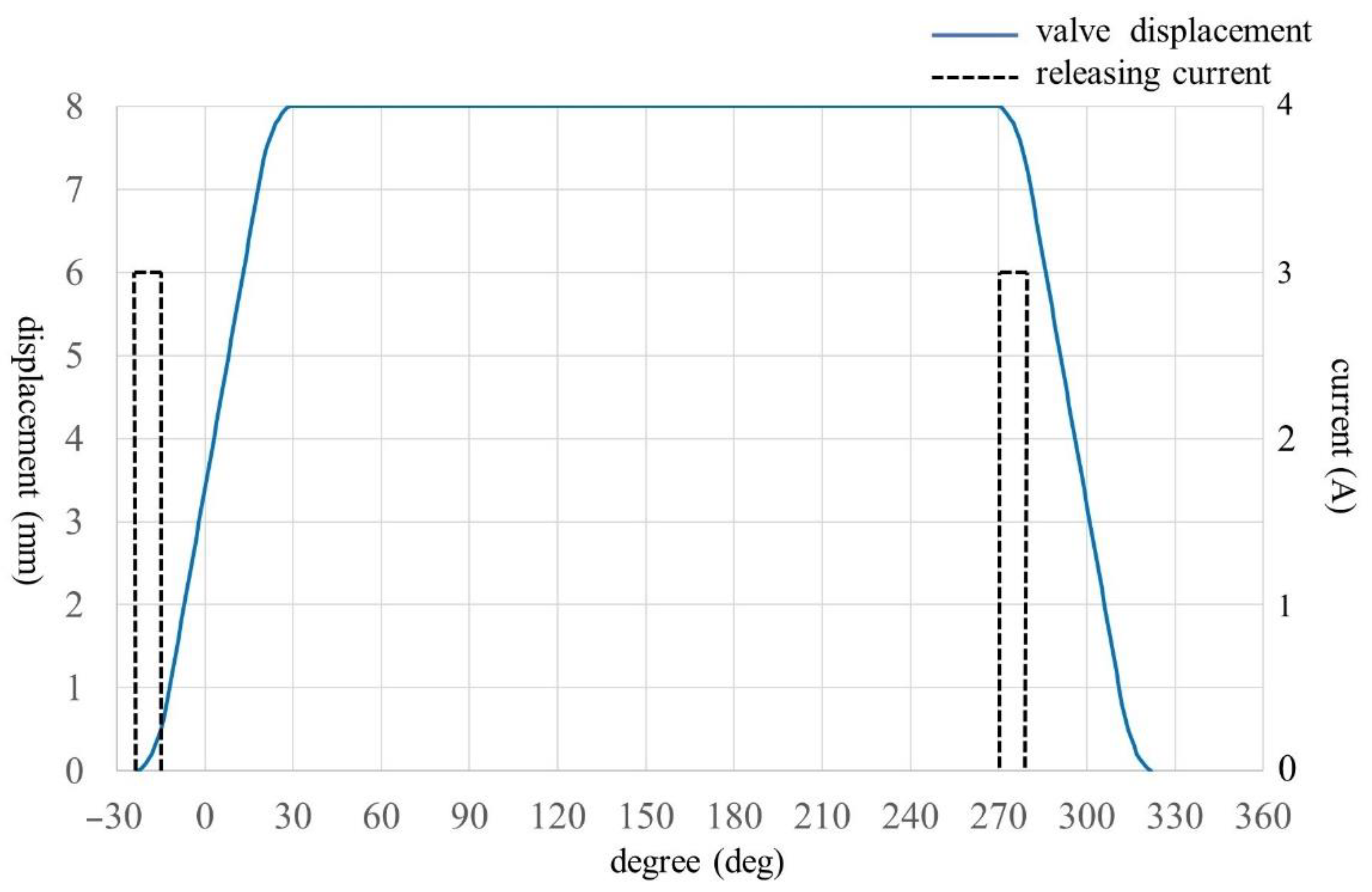
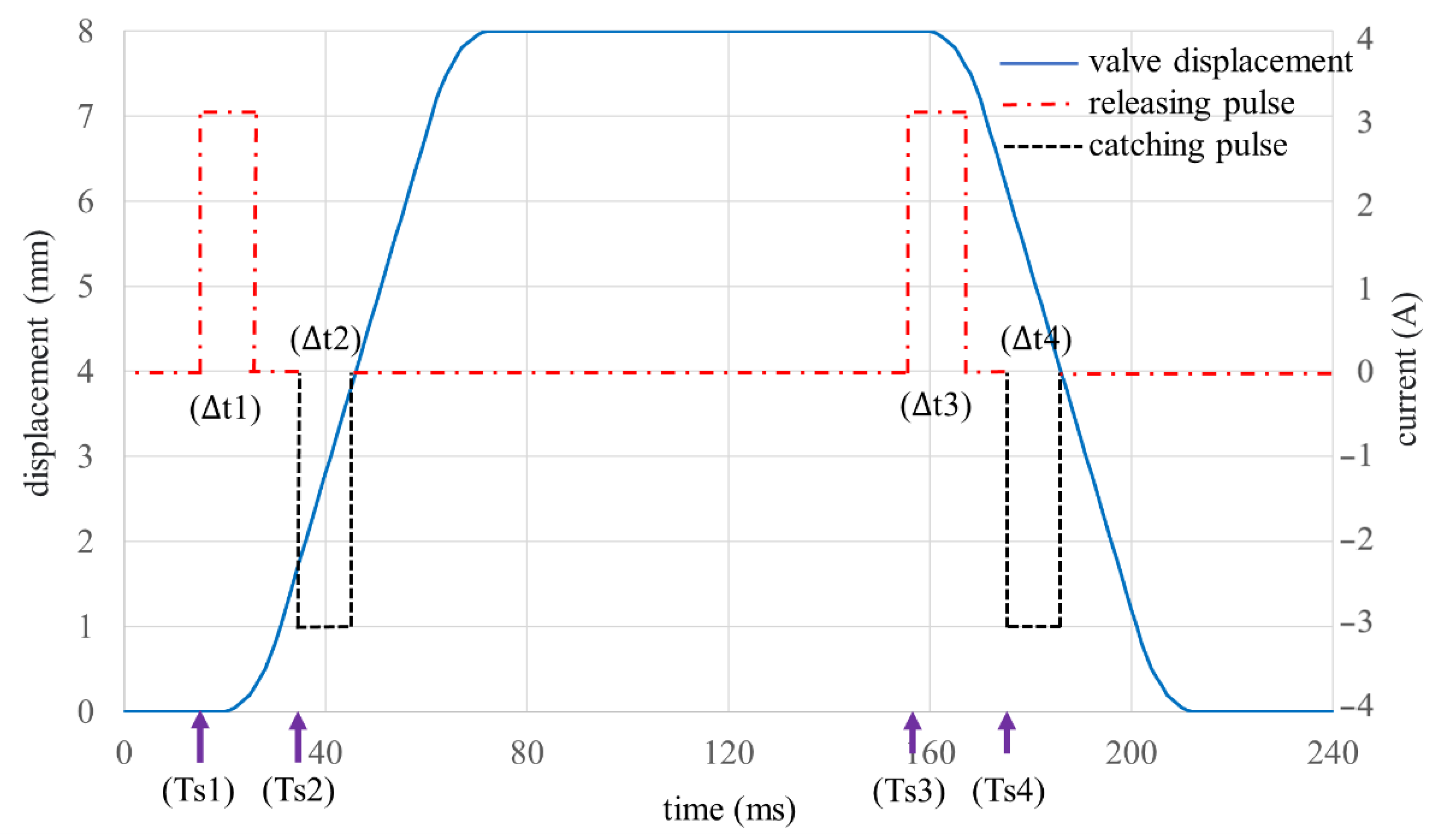
Figure 6 shows the improved operation cycle and release current actuation timings. This new control signal is a combination of releasing the pulse and catching the pulse. When the release pulse is applied to make the armature relieved from the UPM attraction force, the armature moves 0.2 mm away from the PM. The spring force is used to move the armature to the other end. The spring force causes the armature to leave the UPM and move close to the LPM. At this point, the catching pulse is required to overcome the incomplete stroke, as explained in
Figure 5. Due to this, the catching current electromagnetic force pulls the armature much closer to the LPM, i.e., in the range of 0.2 mm (valve displacement at this point is 7.8 mm). Then, the armature is attracted by LPM and opens the valve completely. Similarly, after the release pulse is applied again, the armature moves 0.2 mm away from the LPM (valve displacement is 7.8 mm). Then, the armature moves to the UPM side due to the spring force. There again, the catching current is applied, so that the armature enters the upper PM range, and then it is attracted by UPM. Hence, the air valve is fully closed.
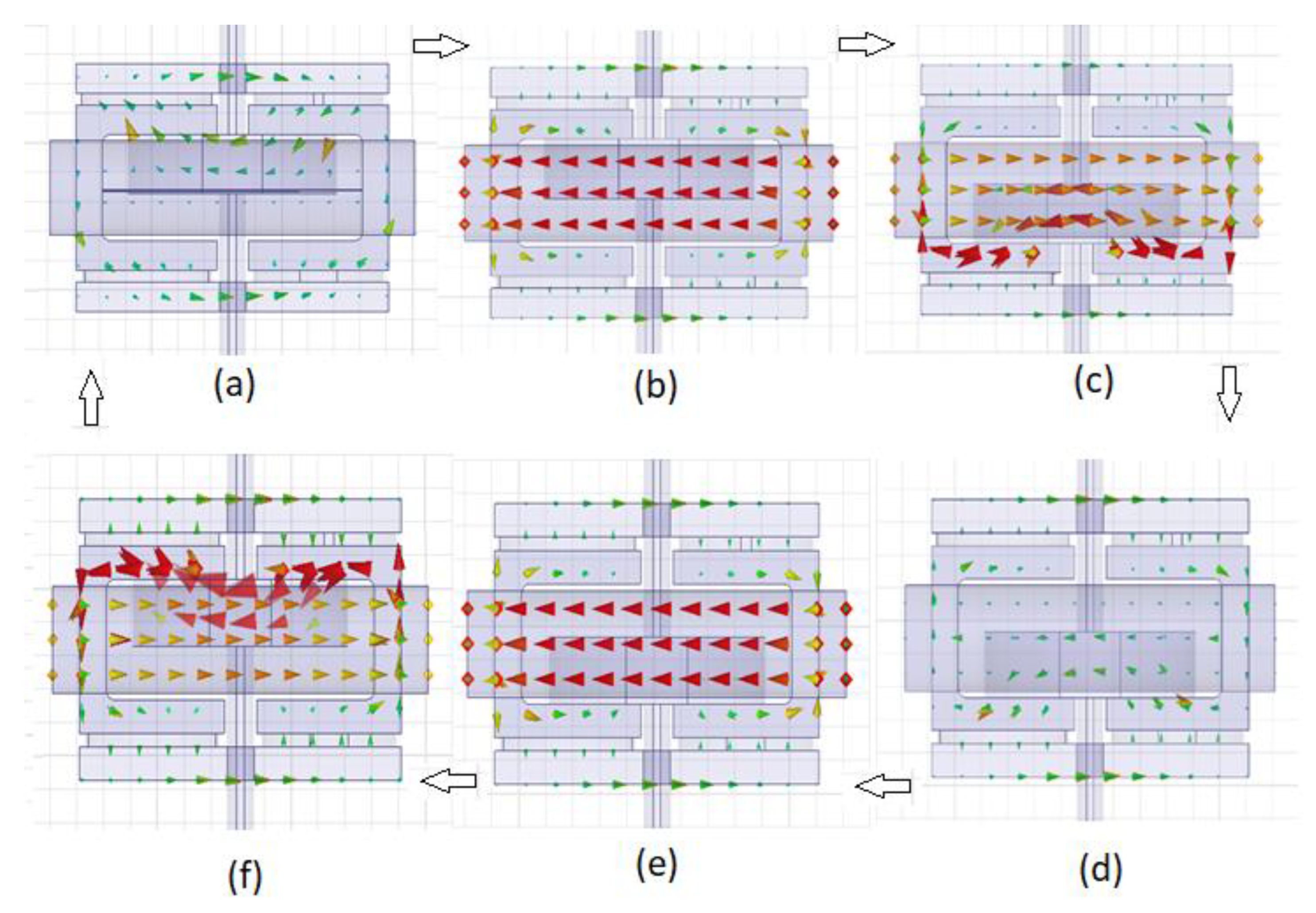
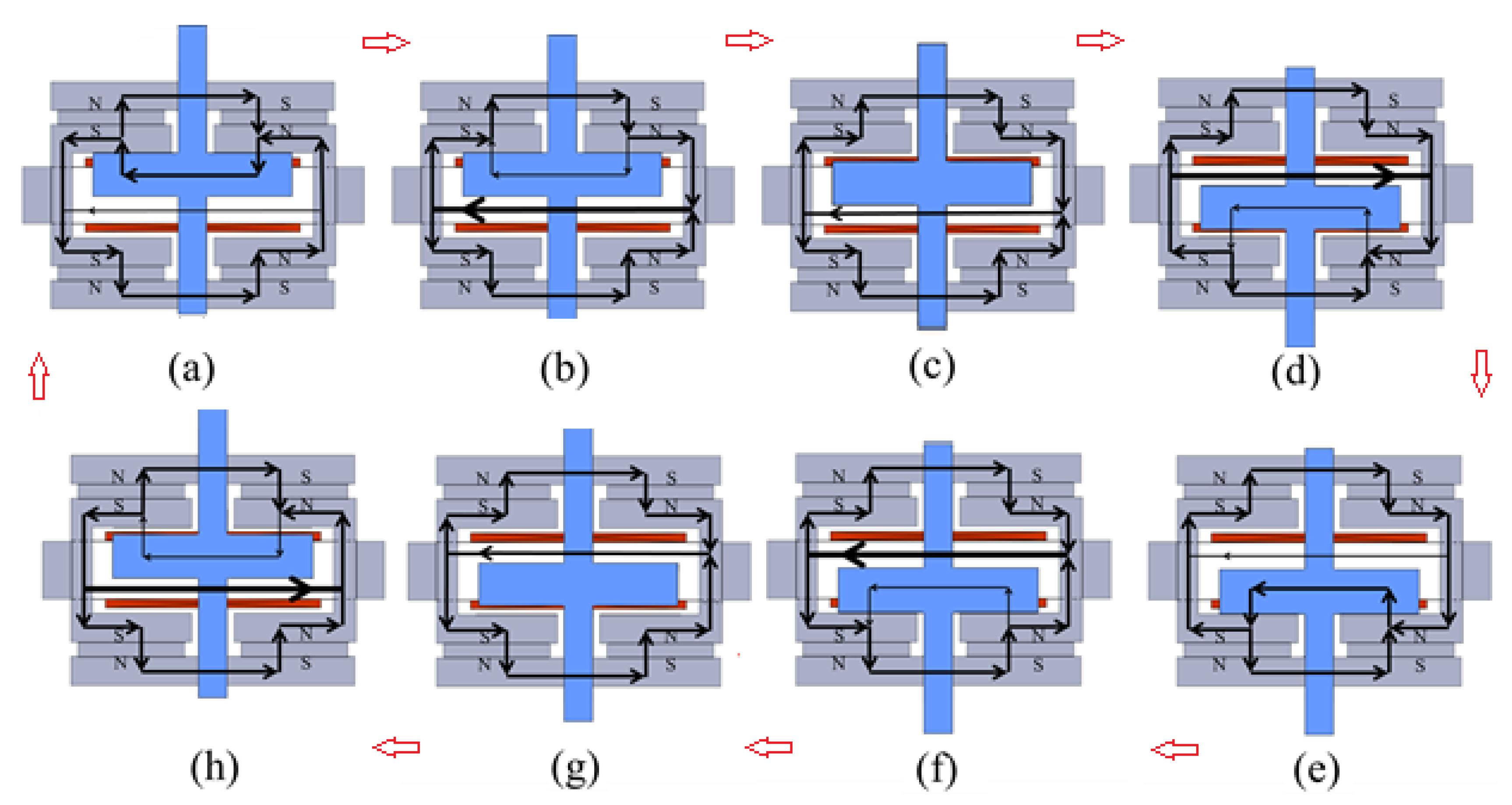
The magnetic simulations of the EM valve operation modes are shown in
Figure 7. Moreover,
Figure 8 illustrates the magnetic circuit diagram for the operation of the EMV. When the EM valve is not in operation, no current is supplied. The magnetic flux of the UPM is with the armature, as shown in
Figure 7a. When the release pulse is applied, the magnetic field that was generated by the guiding coil traps the UPM flux, so that the armature and the UPM are separated. Then, due to the spring force, the armature moves away from the UPM, as shown in
Figure 7b. Then, it is close to the LPM. Next, the catching pulse is applied. The total magnetic field, generated by the guiding coil and the reverse magnetic field of the coil, is directed to the armature through the body to form a loop. This generates a greater attracting force than the original permanent magnet, to attract the armature. When the armature enters the magnetic range of the LPM, the catching pulse is turned off, so that the armature is magnetically attracted by the LPM. At this time, the air valve opens, as shown in
Figure 7c. Similarly,
Figure 7d–f show the valve closing process.
4. Test Setup and Procedure
This section presents the selection of the EM valve components, the experimental equipment, and the testing process. According to the simulation data of the EM valve, when the EM valve does not pass any current, the attraction force of the armature to the body is 198.5 N. When the release current is supplied to release the armature, this attraction force is dropped to 79.6 N. Therefore, it is known from these simulation data that the selection range of the spring is between 79.6 N and 198.5 N. The spring force cannot exceed this range; if it does, the armature will not work. Japanese standard flat wire die springs (KM08×45) were used for this actuator [
23]
When the EM valve is operating, the total stroke of the armature displacement is 8 mm, which was designed to match the EM valve mechanism. The components of the EM valve are the body parts assembly, the permanent magnet placed on the winding of the coil, and the installed spring positioner. N35 high-temperature neodymium disc magnets were used for this actuator. These high-temperature magnets can work at temperatures of up to 300 °C, without losing their permanent magnetic properties [
24]. In addition, the spring, and finally complete the EM valve body. There are two springs in total, which are installed above and below the spring positioner. It must be noted that the spring force of the single side is half of the sum of the springs. The range of a single spring constant after the calculation is between 0.5 kg/mm to 1.26 kg/mm. The EM valve in this study needs to be coiled with a wire, with current applied to the wire to generate a magnetic field to release and attract the armature. To improve the safety of the experimental test, 0.8 mm enameled wire (21AWG) was selected as the coil. The highest withstandable current for this wire is 3.2 A. It is clear from the simulation data that the EM valve must be supplied with a current of 400 ampere-turns. Therefore, 200 turns of enameled wire were coiled on the EM valve, and then a current of was is supplied to reach 400 ampere-turns.
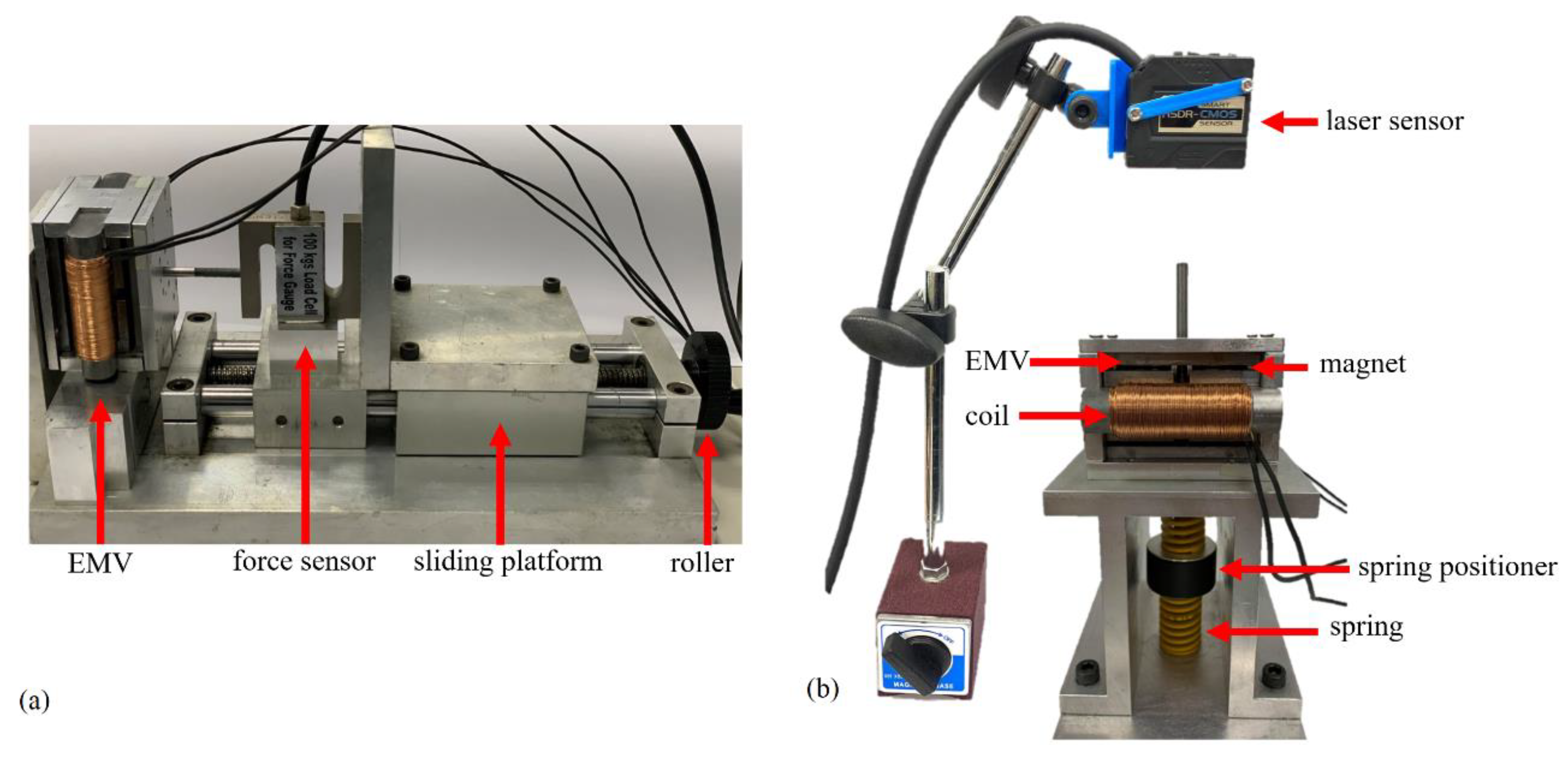
Two kinds of tests were conducted on the proposed EM valve and actuation.
Figure 9a shows the maximum attraction force test platform. It is composed of a manual roller connecting screw to drive the platform. A 100 kg S-type load cell (FG5100) was used to measure the maximum attraction force of the EM valve. Start the test by keeping the armature at the UPM. Use the power supply to provide a fixed current, and the measurement range is 1~3 amperes, to measure sequentially. Start the measurement after the release current is provided. Reset the thrust count value to zero. When the release current is applied, rotate the screw of the test experiment platform to gradually apply thrust, to make the armature gradually leave the upper apex. When the armature is completely separated, stop rotating, and record the instantaneous maximum thrust, which is the release force of the EM valve.
Figure 9b shows the EM valve operation test. A laser displacement sensor is used to measure the armature position with a high resolution of 2 μm and the fastest sampling speed of 1 ms. This experiment uses a GPC-3060D power supply to provide current input. Turn on the power supply to provide a fixed current of 3A, then connect the power supply to the input terminal of the control board, and start the test after confirming that the connection line is correct. This test is divided into six stages, as shown in
Figure 6, which test the time required for the EM valve armature to release from bottom to top (∆t1), the time required for the armature to absorb down to top (∆t2), and the time required for the armature to release from top to bottom. The required time is ∆t3; the time required for armature attraction from top to bottom is ∆t4; the best time for armature attraction from bottom to top is Ts2; and the best time for armature attraction from top to bottom is Ts4.
5. Results
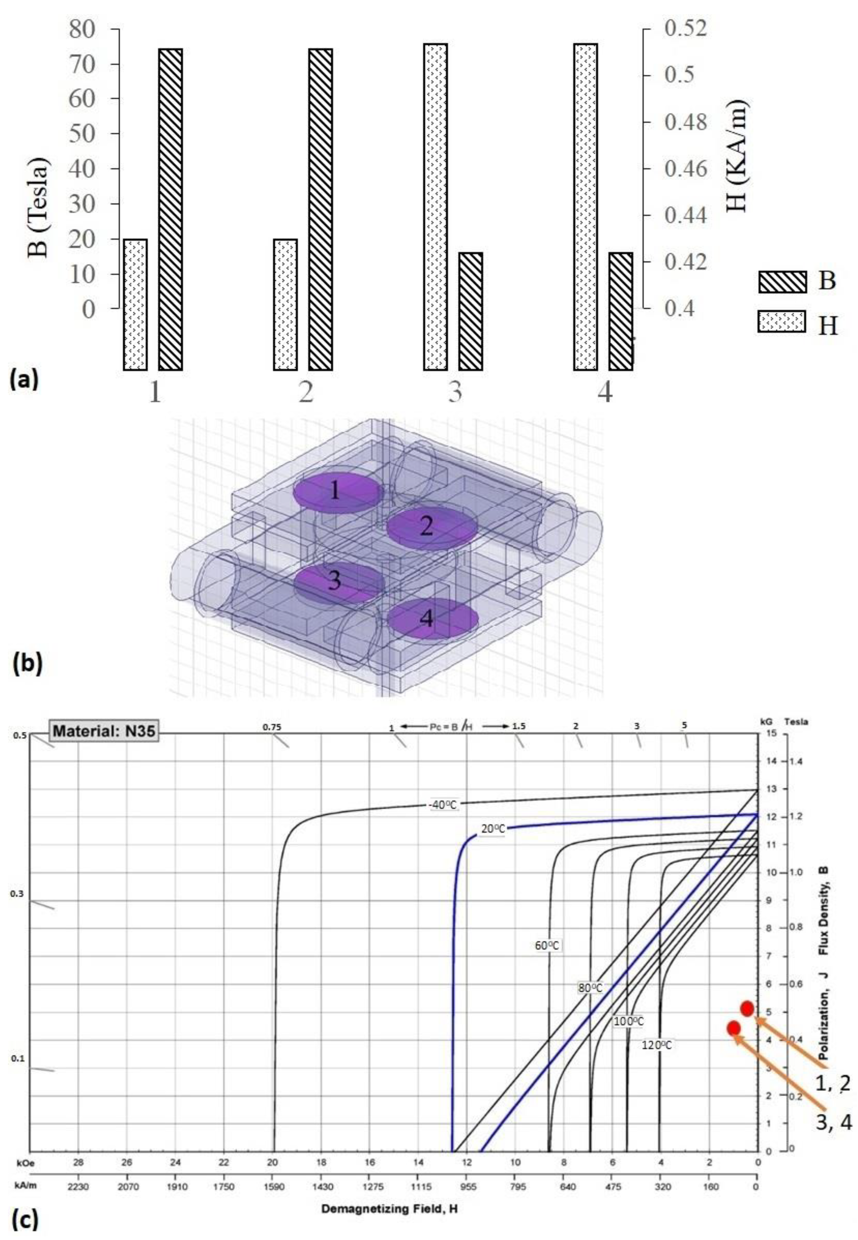
Firstly, it is required to explore whether the improved magnetic circuit will cause the demagnetization of the permanent magnet’s magnetic force. Hence, a simulation analysis was carried out for an in-depth understanding of the demagnetization effect on the magnets when the EM valve is energized with the releasing pulse and catching pulse. As shown in
Figure 10a, the lower circular cross-section of the simulated permanent magnets 1 and 2 is located where the permanent magnets are attached to the armature. When the attraction current is applied, the average magnetic flux density B of the cross-section and the average magnetic field intensity H generated are shown in the BH relationship diagram, as shown in
Figure 10b, and are compared with the demagnetization curve table of the permanent magnet N35 neodymium iron magnet used in the EM valve, as shown in
Figure 10c. The cross-sections of permanent magnets 1 to 4 are all within the working range of BH, which will not cause the demagnetization of the permanent magnet N35. This verifies the durability of the improved EM valve permanent magnet.
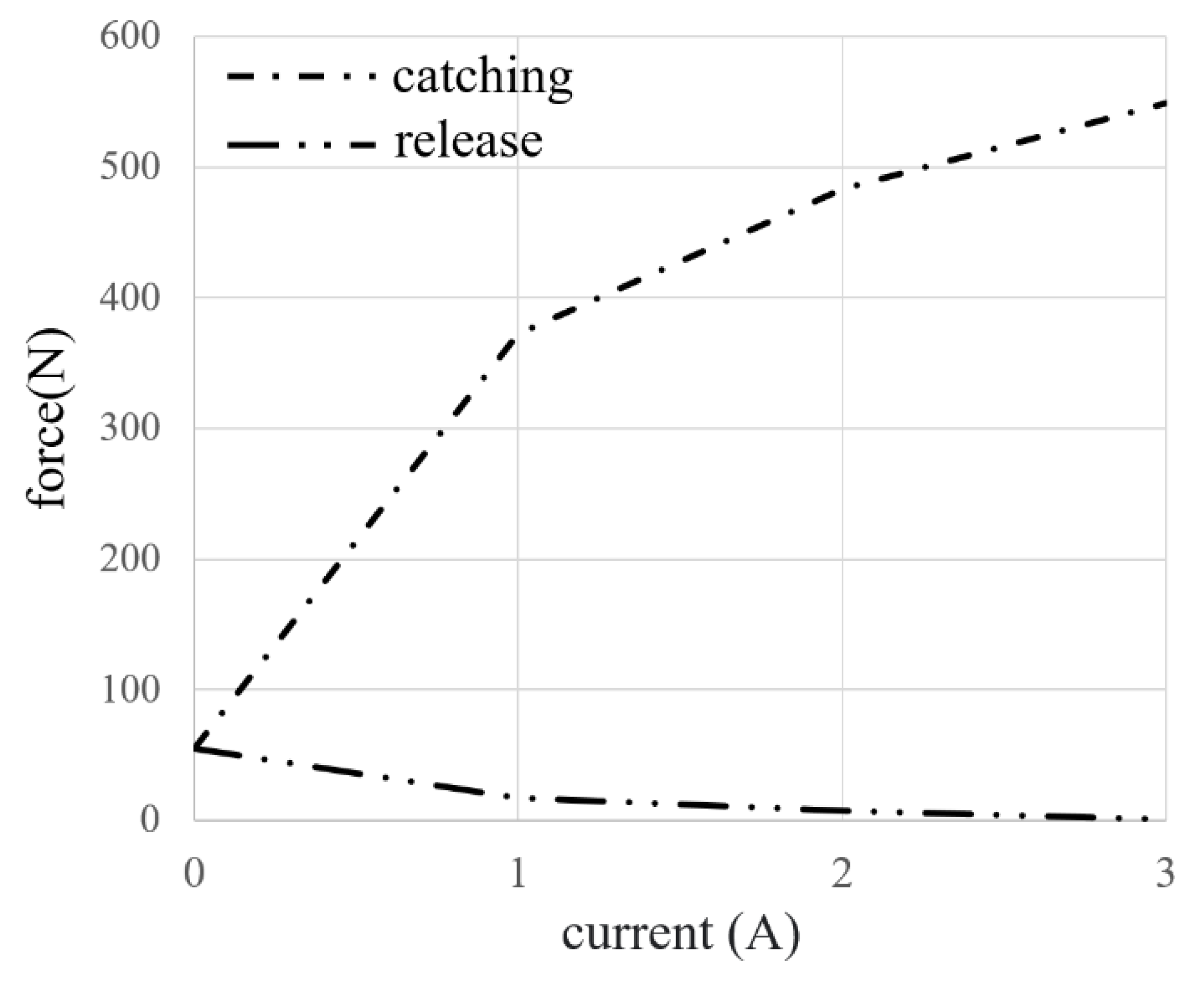
Next, the maximum attraction force, when the releasing pulse or catching pulse is applied, is measured. Through the experimental test results, it is known that the EM valve has different attraction forces under the different currents of the permanent magnet, release, and attraction.
Figure 11 shows the experimental results of the maximum attraction force during the releasing pulse catching pulse. It can be seen that when the EM valve is supplied with a current of 3A, the release force is close to zero, which is very different from the attraction force of 549.2 N. This means that the larger the spring coefficient of elasticity is that can be used, the faster the armature moves, and the higher the engine speed is that can be matched.
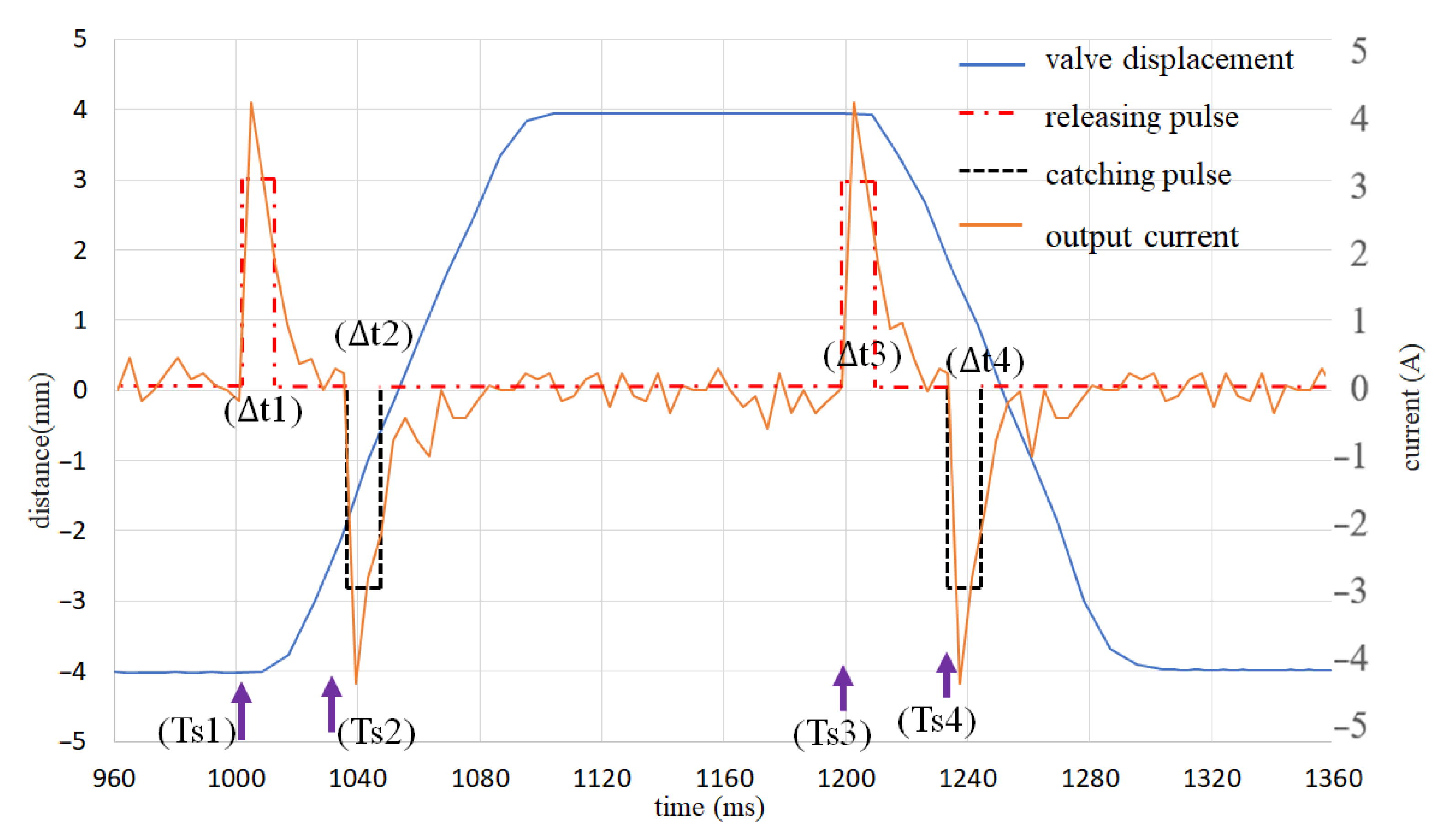
Lastly, the armature release and attraction timing are measured with the EM valve test. As shown in
Figure 12, the release pulse given at Ts1 is 1000 ms. The required time ∆t1 is 10 ms. The armature releases and leaves the lower vertex. After the armature is released, Ts2 is 1035 ms. When the time required to pass the suction pulse ∆t2 is 10 ms, the output pulse is stopped, and the armature reaches the upper peak. When Ts3 is 1200 ms, the release pulse is passed, and the required time ∆t3 is 10 ms for the armature to leave the upper peak. When Ts4 is 1235 ms after the armature is released, the time required to pass the attraction pulse ∆t4 is 10 ms, and then the output pulse is stopped. The armature reaches the lower peak.
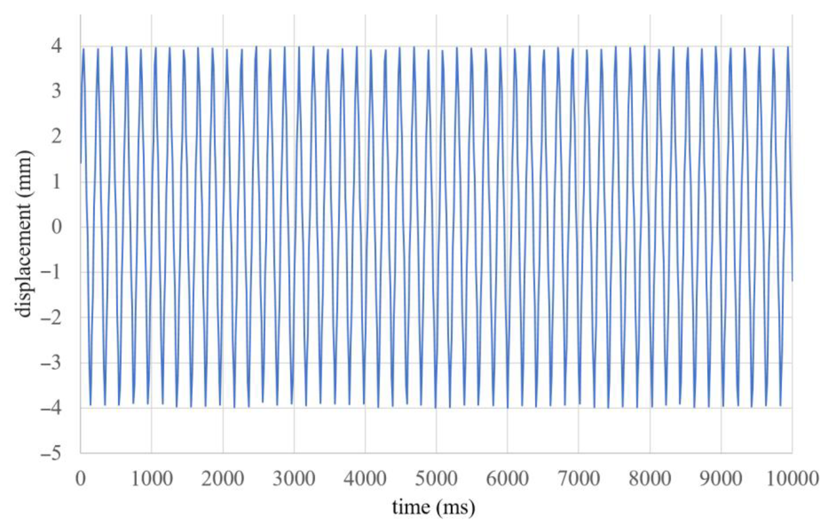
The test is completed, and the results are shown in
Figure 13. The fastest speed of the air valve is 300 rpm. According to the above electronic valve test experiment, it is found that the time required for the armature of the electronic valve to go from the top to the bottom or from the bottom to the top of the armature are the same, at 104 ms. This time does not reach the idling speed of the internal combustion engine. In the future, it will be important to reduce this time by improving the spring coefficient and replacing the permanent magnet with a higher magnetic force. However, the amperage of the input pulse also needs to increase to raise the adsorption force of the electronic valve to match the high-stiffness springs.
At present, the guided composite electronic valve has not been actually used in the engine, but if it is in the future then this study can be said to be a very outstanding contribution, because this paper demonstrates the permanent magnet electronic valve under long-term operation without demagnetization. This valve actuator can achieve a variable timing to the engine with low energy consumption, and the electronic valve can also cooperate with the cylinder stop technology (actuation technique in multiple cylinders), which has a more significant effect on low energy consumption.


