Featured Application
The proposed method can be used to preliminarily determine the rationality of stator–structural topology and consider rotor–stator interference flow excitation without the need for performing numerical simulations of three-dimensional unsteady CFD.
Abstract
Based on the computation and analysis of three-dimensional unsteady flow induced by rotor/stator interactions, the characteristics of flow excitation towards bladed disks were studied, including frequency components and circumferential wave components. By combining the resonant condition of bladed disks, a design principle was derived for determining the stator structural period from the view of averting resonance. The influences of different topologies on mistuned stators are also studied, for which the sectional non-uniform mistuned stator showed a clear effect in lowering the amplitude of formal excitation characteristics compared to tuned cases. A formula was developed to predict frequency components and circumferential wave components in the wake of both tuned and mistuned stators, making it easier to determine stator structural topologies in the design phase without performing three-dimensional unsteady CFD.
1. Introduction
Unsteady rotor/stator interference flow in aeroengines is the main excitation source causing serious cycle fatigue damage for bladed disks [1].
In early analyses of structural forced-response vibrations in the aeroengine industry, most designers used traditional Campbell diagrams to predict the forced resonance speed of the blade and disk. Using Campbell diagrams to identify the resonance of rotor structures is a rapid and convenient method for expressing the variation characteristics of all components of rotor vibration in the whole speed range by taking the vibration amplitude of monitoring points as a function of speed and frequency [2,3]. Campbell diagrams only consider that the excitation component contains components equal to the resonant frequency of the blade structure. These conditions are valid for the analysis of a single blade structure. However, the Campbell diagram method does not consider the effect of the circumferential wave spectrum on the resonance of the periodic symmetric structure in aeroengines [4].
Resonance conditions for periodic symmetric bladed disk systems have been studied previously. Xin [5] pointed out that the resonance conditions of a bladed disk need to meet an equal excitation frequency (the natural frequency of a certain mode of the structure), while the excitation order and the structure of the order mode shape nodal diameter must also be equal. Yao [6] described the resonance conditions of the blade disk system as follows: the excitation frequency is equal to the natural frequency, and the difference between the number of stators is equal to the number of blade nodal diameters of a certain mode. This condition can be written as:
where is the number of stator blades, is the number of rotor blades, and is the number of mode nodal diameters that can be excited. Studies have shown that a more general expression should be based on the resonance conditions of rotationally symmetric structures obtained by Wildheim [7], written in the following form:
This flow-induced vibration condition of periodic symmetric structures can not only be used for the periodic harmonic excitation of engine internal flow fields, but also for periodic mistuned excitation.
Rotor–stator interference flow fields are another key point in bladed disk vibration suppression. Zhao et al. [8] studied the effect of dynamic and static interference of clearance flow in fluid machinery caused by changes in rotational speed; they found that controlling the rotating speed within a reasonable range can effectively improve the characteristics of the clearance flow. Faller and Alan [9] used a rotor–stator system experiment to quantitatively analyze the critical Reynolds number of the Ekman laminar boundary layer. Owen and Bayley [10,11] also studied the influence of different rotating disc speeds on flow through various experiments, obtaining the torque coefficient of the disc and making theoretical predictions. Breard [12,13] used a 3D integrated time-domain code and conducted parametric studies for a high-pressure turbine stage with 36 stator and 90 rotor blades. For example, for individual parameters, the amplitude of the excitation could be proportional to the imposed variation; thus, Bladh [14] performed investigations related to the leakage-induced blade excitation from shrouded vane segments found in industrial gas turbine compressors. The obtained results indicated that the excitation induced by the inter-segment gap leakage flows is distinctly multi-harmonic and unexpectedly strong.
Structural mistuning means that the blades in a blade row are slightly different in structure (such as mass, stiffness, damping, geometric size, etc.); therefore, they have different natural frequencies [15,16,17,18]. Studies on the influence of structurally mistuned components on the fluid-induced vibration of inlet guide blades when introduced to the guide blade and rotor blade showed that the non-uniform distribution of the guide blade could effectively reduce the unsteady internal stress of the guide blade [19,20,21,22,23]. Figaschewsky et al. [24] proposed a construction method of flow field detuning and measured the influence of flow field detuning on blade and disc structures through modal force. Sullivan [25] and Edwards [26] designed a non-uniform grid pitch for main helicopter suspension wings and showed that the non-uniform grid pitch had a noise reduction effect.
It can be seen that mistuning of a rotating structure has a good suppression effect on flutter but may increase the forced response [27,28,29]. However, aerodynamic mistuned designs for stator blades may be an effective way to reduce blade forcing responses [30]. Compared with symmetric cascades, the amplitude of forcing functions due to wake passing presents an increase for blended rotors [31]: 10% detuning resulted in a lower critical reduced frequency value compared to the baseline rotor, thereby demonstrating enhancement of aerodynamic detuning stability [32]. Therefore, a geometrically mistuned design was introduced into the stator to achieve changes in wake excitation characteristics towards the blade disk system, including frequency components and circumferential wave components. Combined with the resonant conditions of bladed disks, design principles have been proposed for determining the stator structural period and the topology of mistuned stators in order to suppress vibrations in bladed disk systems.
2. Materials and Methods
2.1. Resonance Analysis Theory of Bladed Disk Systems
Blade disks typically exhibit a periodic symmetric structure, and their basic vibration forms are fan-shape vibration and umbrella-shape vibration, which are both periodically symmetrical. Fan-shape vibration is marked by some diameter lines with zero displacement in the vibration mode; thus, it is also called nodal diameter vibration [1,2]. The two-nodal diameter mode of a Rotor67 bladed disk system is shown in Figure 1. Umbrella-type vibration is marked by some circular curves with zero displacement in the vibration mode; thus, it is also called nodal circular vibration. This property can be determined from the analytical expression of bladed disk system vibration.
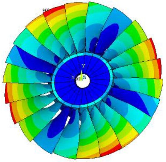
Figure 1.
Rotor67 bladed disk two-nodal diameter mode.
2.2. Resonance Conditions of Bladed Disk Systems
For a bladed disk system with a blade number of , if only the vibration perpendicular to the disk surface is considered, the conditions under which the mode with nodal diameter can be excited are [7]:
where is the natural frequency of the mode whose nodal diameter number is and is the rotation speed.
The left side of Equation (3) is determined by the characteristics of the bladed disk system, and the right side is determined by the characteristics of excitation force. The resonance conditions show that the resonance of a bladed disk system involves a common parameter , which is related to structure and excitation, in addition to the frequency. For a structure, is the parameter describing the vibration mode of bladed disk systems, i.e., the nodal diameter number. For excitation force, is the parameter describing the circumferential wave number of excitation force.
If we set a stator (inlet guide vane, IGV) upstream of the bladed disk system, whose blade number is and angular velocity is ω, then the excitation frequency towards the bladed disk system from the wake of the stator is:
The order of excitation is a multiple of the rotational speed; here, we define the engine order (EO) as:
The subsequent resonance condition is:
The conditions of nodal diameter resonance become:
The above equation shows that, after the dynamic characteristics of bladed disk system are determined (, are determined), the period number of the stator becomes a key factor in resonance.
2.3. Resonance Analysis of Bladed Disk Systems
The resonance conditions of a bladed disk system are given by Equation (3), which involves two common parameters in structure and excitation: nodal diameter number and frequency. Therefore, the resonance frequency and excitation frequency of a bladed disk system with a change in are drawn on the same nodal diameter frequency diagram, and the intersection of the black and red line are the resonance points, as depicted in Figure 2. In the Rotor67 bladed disk system, there are 22 blades, and the angular velocity is 16,043 r/min. The inherent frequencies of the Rotor67 bladed disk can be obtained using finite element software (ANSYS). The ZZENF diagram [7] of the Rotor67 bladed disk can then be obtained, as shown in Figure 2.
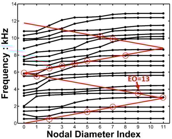
Figure 2.
ZZENF diagram of the Rotor67 bladed disk system. Zig-zag-shaped excitation line (red) in the nodal diameters versus frequency diagram (black spot). Possible resonances are marked with red circles.
The frequencies of bladed disk systems are not continuous with the nodal diameter number; thus, if the intersection of the frequency diagram and excitation line falls on a plumb line crossing an integer abscissa, this is the resonance point. The point EO = 13 in Figure 2 is the intersection of the excitation line and a frequency diagram, and it is exactly on the plumb line crossing the x-coordinate of 9; therefore, it is a resonance point. All the resonance points are listed in Table 1.

Table 1.
Rotor67 bladed disk system resonance analysis table.
The components of wake excitation of a stator are key to avoiding resonance after the resonance conditions are determined. The period number of the stator should not only ensure that the flow excitation does not contain the resonance frequency components, but also the frequency component corresponding to the nodal diameter of the resonance mode.
2.4. Unsteady Flow Field Calculations and Setting Excitation Monitor Points
An unsteady three-dimensional flow field was constructed based on the Rotor67 moving blade shape, and the NACA0012 symmetrical blade airfoil was used to build the upstream stator (IGV). Inlet zone and outlet zone were built, which had a length of 10 times the chord length of the rotor blade. In order to study the influence of different numbers of stators on the excitation characteristics of the flow field, different topologies of stators were designed. Monitoring points were set at the root, 50% height, and at the top of the blade. At each height, the leading edge, blade basin, trailing edge, and blade back of each height were numbered 1–12 on each rotor blade; a total of 264 monitor points were set on 22 rotor blades, as shown in Figure 3.
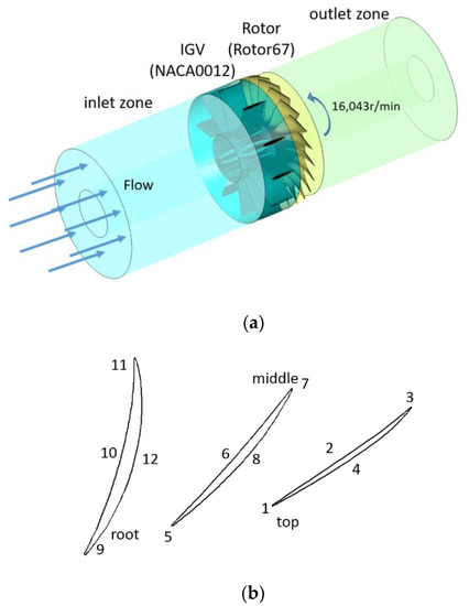
Figure 3.
Description of (a) mesh of the fluid domain and (b) monitoring points on the rotor.
The numerical simulations utilize the 3D unsteady Reynolds-Averaged Navier–Stokes (RANS) solver ANSYS CFX which uses a finite volume method to compute the flow field. Four sets of grids were designed to verify grid independence, with numbers of N1 = 2 million, N2 = 3 million, N3 = 5 million, and N4 = 8 million. The CFD software CFX was used for numerical simulations. Other conditions were set as follows: rotating speed was 16,043 r/min; the total pressure at the inlet was 101,325 Pa; and the total temperature was 288.15 K. According to the radial balance equation, the static pressure at the outlet was set to 122,000 Pa at the height of the blade with a radius of 50%. The K-Epsilon turbulence model was selected to transfer a transient stator at the junction and the wall function was set to standard wall function. Other boundaries were set as the no-slip wall and tip clearance was ignored. The total pressure value at point 5 (50% height, leading edge) was chosen for comparisons. The results of the independent grid study are shown in Table 2. The height of the first layer from the solid surface is set to 1 × 10⁻⁶ m to ensure that y+ is approximately 1.0 and the total grid nodes are 3.14 (N2) million.
Table 2.
Results of the independent grid study.
In order to ensure the accuracy of the circumferential excitation calculations, unsteady calculations of the two rows were performed with the whole circle grid. Considering the unsteady state calculation speed, the number of mesh nodes was set at the N2 level, which varied slightly with different stator designs: the total number of grid nodes in the whole fluid domain was between 3,000,000 and 3,200,000.
In the calculations of unsteady flow fields, the calculation results of steady flow field were taken as the initial field. The time step number of each static sub-channel was set as , and the single time step size was as follows (taking as an example):
The convergence conditions of unsteady calculations are when the root-mean-square of the total pressure at the residual converges to lower than 0.01%. Figure 4 shows the contours of the pressure field behind the rotor blade and the cloud picture of the static pressure field at 50% blade height. It can be seen from the figure that, under conditions of uniform air intake, the static pressure field at the compressor outlet at any time presents a periodic distribution.
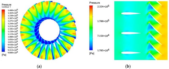
Figure 4.
The (a) cloud picture of the pressure field behind the rotor blade; (b) cloud picture of static pressure field distribution at 50% blade height.
Figure 5a depicts the pressure timing signals of 12 monitor points on one blade within a cycle of compressor rotation (with the mean pressure removed). The frequency spectrum of pressure pulsation at each point can be obtained by Fourier transform. Figure 5b shows the circumferential pressure changes in the 12 monitoring points at a certain moment (when the mean pressure is removed). The circumferential wave spectrum of pressure changes at each position can be obtained by applying Fourier transform to the circumferential change curve of instantaneous pressure at the same time at each position.
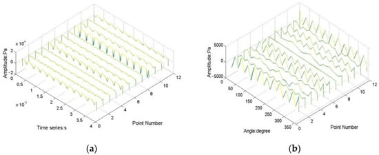
Figure 5.
The (a) pressure time signals (one rotating period) at each monitoring point; (b) circumferential pressure distribution at each monitoring point (at one moment).
3. Excitation Characteristics of Tuned Stators and Blade Period Design
The resonance conditions of the bladed disk system indicate that the frequency and circumferential wave spectrum of fluid excitation are key factors to induce bladed disk resonance. The characteristic components of these fluid excitations are directly influenced by the number of stator blades.
3.1. Effect of Stator Blade Number on Excitation towards the Bladed Disk
First, is taken as an analysis example. Figure 6 shows the frequency spectra of the monitoring points at the leading edge, basin, back, and railing edges of the rotor blade. In order to show the multiple relationships between the frequency of unsteady aerodynamic force and the fundamental frequency of the rotor speed, EO is adopted as an abscissa. The excitation components at the root, middle, and tip of the blade are distinguished by different colors.
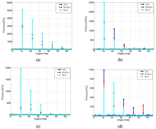
Figure 6.
Frequency spectra of monitoring points on the rotor (): (a) leading edge; (b) basin; (c) back; and (d) trailing edge.
Figure 6 shows that the main frequency components of pressure pulsation (with the mean pressure removed) at each point correspond to the order excitation of stator wake, i.e., the order of excitation is the number of stator period 11 and its multiple, and the amplitude at the leading edge is the largest. Except for the trailing edge, the relative amplitude of frequency components at each point basically meets the law that the higher the order, the smaller the amplitude. Generally speaking, the fluid pressure pulsation amplitude is the highest at the blade root, followed by that at the middle of the blade, with the smallest at the blade tip.
The frequency characteristics of excitation at the trailing edge have something in common with the leading edge and the basin—the distributions are the same—but the amplitude of each order is not consistent. The amplitude of EO = 22 = and the excitation component at the blade root are the largest, indicating that the excitation at the trailing edge is more sensitive to the number of rotor blades. However, its overall amplitude is much smaller than that of the leading edge and the basin, and the excitation components at this place have little contribution to the pressure pulsation excitation components of the blade disk system.
Pressure pulsation at the leading edge of the rotor blade is much larger than that at other monitoring points, which has significant representativeness. Figure 7 shows the spectrum of primitive-level leading edge monitoring points in moving blades corresponding to three different values () in working conditions.
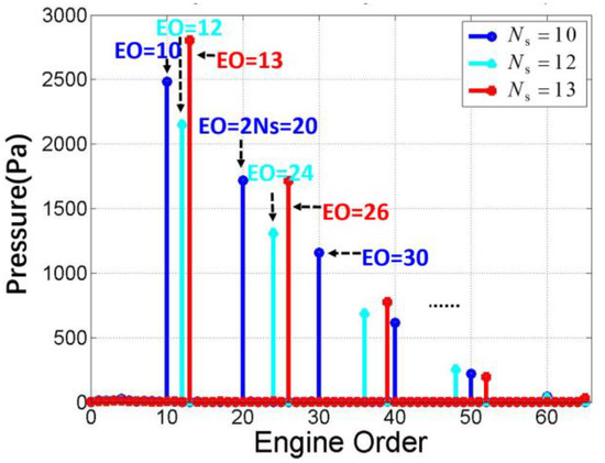
Figure 7.
Frequency spectrum of monitoring point pressure at the leading edge of the rotor.
By analyzing the excitation spectra generated by the above four conditions with different static sub-periods (Figure 6 and Figure 7), the following conclusions can be drawn:
- (1)
- The excitation generated by the stator with the period number of on the downstream rotor blade includes each frequency component corresponding to the wake excitation order, namely, ;
- (2)
- Among all amplitudes of the frequency components, order is the largest, and the amplitude of the other component () decreases with the increase in ;
- (3)
- In general, the amplitude of is less than half that of the amplitude of the main excitation (), while the higher-order amplitude becomes smaller.
3.2. The Circumferential Wave Distribution Characteristics of Excitations and the Influence of the Stator Blade Number
Firstly, take as an example. For a bladed disk system with blades, the maximum nodal diameter number of its nodal mode vibration is:
When , the maximum nodal path number is 11. Therefore, when analyzing the circumferential wave components of the excitation, according to the resonance conditions, the cycle wave number can be set to 11. Figure 8 shows the circumferential wave spectrum distribution pressure at the monitoring points at the leading edge, basin, back, and trailing edges. The excitation components at the root, middle, and tip of the blade are distinguished by different colors.
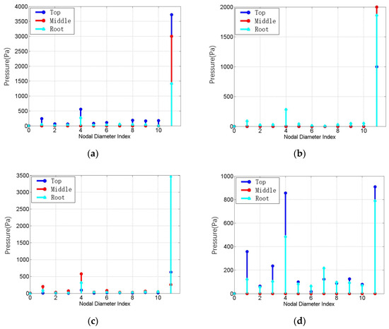
Figure 8.
Circumferential wave spectrum of monitoring point pressure () at: (a) the leading edge; (b) the basin; (c) the back; and (d) the trailing edge.
It can be seen from Figure 8 that harmonic excitation from 1 to 11 is reflected in the pressure circumferential wave spectrum distribution, and the components corresponding to 11 () are dominant, except at the trailing edge which also exhibits the smallest amplitude.
The circumferential wave spectrum at the trailing edge is complicated. The reason for this phenomenon is that the excitation at the trailing edge is more sensitive to the number of rotor blades (). However, its overall amplitude is much smaller than that of the leading edge and the basin, and the excitation components here have little contribution to the pressure pulsation excitation components of the blade disk system.
Figure 9 shows the wave spectra of pressure amplitudes for four monitoring points at the middle height of the rotor blade corresponding to three working conditions with different stator numbers ().
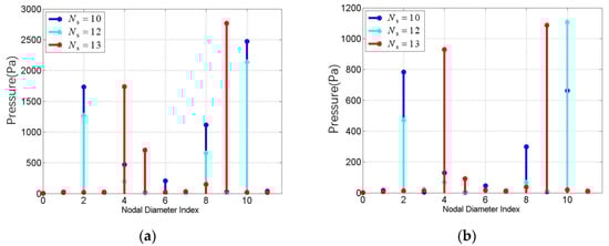
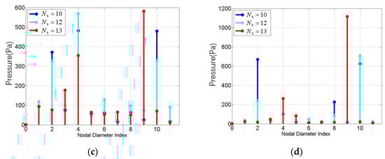
Figure 9.
Circumferential wave spectrum of monitoring point pressure on rotors with different stator blade numbers at: (a) the leading edge; (b) the basin; (c) the back; and (d) the trailing edge.
By analyzing the excitation spectrum generated by different stator blade numbers (Figure 8 and Figure 9), the following conclusions can be obtained:
(1) The circumferential wave distribution of the excitation generated by the stator structure with the set period number on the downstream rotor structure contains various harmonic components; the main harmonic components are:, , , , and . It is not difficult to find that the expression of harmonic excitation above is consistent with the expression of nodal diameter numbers derived from Equation (3), namely:
where ; Thus, the main harmonic component of the circumferential wave distribution of the excitation generated by the stator (blade number ) is given by Equation (10);
(2) In the excitation spectrum, the amplitude of harmonic excitation corresponding to is the largest, and other components’ amplitudes decrease with the increased order of the excitation spectrum. This is consistent with the relative magnitude of the frequency component.
3.3. Stator Number Design to Avoid Bladed Disk Resonance
In this section, the Rotor67 bladed disk system is taken as an example to illustrate how to determine the period number of the stator (IGV) in order to avoid resonance.
For bladed disks with 22 blades, as in this study, the main frequency components of wake excitation generated by the stator with the number of structural periods are:
The main excitation components from the stator wake are:
Consider three options, . Table 3 and Table 4 give the frequency component and circumferential wave components, respectively, in the excitation of the flow field of rotational static interference corresponding to these three different choices.
Table 3.
Stator wake excitation frequency components with respective periods.
Table 4.
Excitation harmonic components in the wake of the stator with respective periods.
By comparing Table 2 and Table 3 with the resonance analysis results of the bladed disk structure (Table 1), it can be seen that:
- (1)
- When , the excitation component with excitation order 13 and circumferential wave number 9 will excite the modal resonance with nodal diameter ;
- (2)
- When , the excitation component with the excitation order of 30 and the circumferential wave number of 8 will excite the modal resonance with nodal diameter ;
- (3)
- When , the excitation does not contain the frequency component or circumferential wave component that causes resonance. Therefore, for the Rotor67 blade disk with 22 moving blades, resonance can be avoided with an upstream stator .
Figure 10 presents the frequency spectrum and circumferential wave spectrum of excitation at the primary-level leading edge monitoring point in the moving blade under the working condition of , based on three-dimensional unsteady flow field analysis. Their components are completely consistent with the values in Table 2 and Table 3, and the relative amplitude of each component is also consistent with the above analysis results.
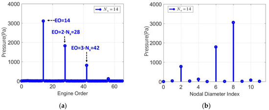
Figure 10.
Wake at the leading edge of rotor blades (): (a) frequency spectrum; (b) circumferential wave spectrum.
Using the same method, the rationality of the stator number (i.e., whether or not it will cause resonance) can be judged. Through numerical analysis, it has been shown that this method can determine the rationality of the stator–structural period without the need to perform numerical simulations of three-dimensional unsteady flow induced by rotor/stator interactions.
4. Excitation Characteristics of Mistuned Stators and Its Effect in Reducing Excitation Amplitude
4.1. Mistuned Stator Pattern and Naming Rules
In this paper, two types of mistuned stator distribution have been defined: asymmetric mistuned stators and sectional non-uniform mistuned stators.
Asymmetric mistuned means that the whole circle of blades is divided into two sections with the angles between blades in each section being the same, whereas the angles between blades in another half are different. As shown in Figure 11a, the stator cascade is divided in two halves: one where the blade angle is and the other where the blade angle is . For the asymmetric mistuned stator, we define the name as:. Therefore, the asymmetric mistuned stator in Figure 9 should be named: .
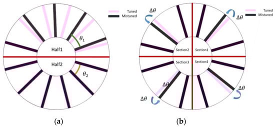
Figure 11.
Two types of mistuned stators: (a) asymmetric mistuned stator and (b) sectional non-uniform mistuned stator.
Sectional non-uniform mistuned means the whole circle of blades is divided into sections, where there are blades in each section. One blade in the same phase of each section is chosen, and this is adjusted in the same direction with the same angle or displacement (along the rotation axis), as shown in Figure 11b. For the sectional non-uniform mistuned stator, the name can be defined as: or . Therefore, the asymmetric mistuned stator in Figure 9b should be named: .
In order to study the excitation characteristics of different mistuned stators, four different mistuned forms of stator were designed, as shown in Table 5.
Table 5.
Four different mistuned forms.
4.2. Asymmetric Mistuned Stators and Their Effect on Excitation towards Bladed Disks
Figure 12 presents a comparison of the wake excitation frequency spectrum on bladed disk systems under the two asymmetric mistuned stator conditions of i: and ii: , with tuned conditions: and .
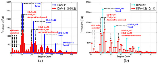
Figure 12.
Frequency spectrum of asymmetric mistuned stators: (a) and (b) .
Compared to the tuned stator, the main components of the asymmetric design’s wake excitation amplitude were reduced, whereas the components increased. The components can be described in three parts.
(1) The parts include: fundamental frequency , , and its multiplication frequency of the fundamental frequency. The amplitudes of these two fundamental frequencies are close, about one-half of the amplitude of the tuned component, namely:
(2) The adjacent frequency components of , , and their multiplication frequency’s adjacent components are:
(3) Odd order excitation components with a small amplitude are:
This phenomenon can be explained from the perspective of energy: in the case of tuned stators, the order of flow excitation is dominated by and its multiple components, which is relatively simple, and the energy concentration leads to a higher amplitude. When the stator is mistuned, the main components of the excitation order are transformed into a frequency band related to and . Compared to the tuned case, the energy is dispersed, resulting in a significant decrease in amplitude.
Figure 13 presents a comparison of wake excitation circumferential wave spectrum on bladed disk systems under the two asymmetric mistuned stator conditions of i: and ii: , with tuned conditions: and .
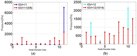
Figure 13.
Circumferential wave spectrum of asymmetric mistuned stators: (a) , (b) .
Compared to tuned stators, amplitude of main circumferential wave excitation induced by asymmetric mistuned stators was reduced, although the components increased.
Combined with the resonance conditions of the Rotor67 bladed disk detailed in Table 1, after mistuning the stator, the amplitude of excitation decreased significantly, but the order excitation that could arouse resonance increased.
With , for example, the excitation frequency components that may arouse resonance include the excitations of and for the tuned case. However, in the case of asymmetric mistuned stators, , the amplitude of is halved and that of becomes zero. However, the new order excitation components that may arouse resonance are as follows: . Similar results can be obtained from the analysis of .
Compared to the tuned cases, the number of components may arouse rapidly increasing resonance; asymmetric mistuned stators are not suitable for application.
4.3. Sectional Non-Uniform Mistuned Stators and Their Effect on Excitation towards Bladed Disks
A total of six sectional non-uniform mistuned stators were designed, as shown in Table 5.
Notably, in case IV, the 12 stator blades are divided into six sectors along the circumferential direction, and 1 blade in each sector moves 5 mm away from the rotor along the axial direction.
It can be seen from Figure 14a that, compared to the tuned situation, the wake excitation component amplitude of the sectional non-uniform mistuned stator was reduced, whereas the components increased. With sectional non-uniform mistuned stators, the minimum periodic cycle turned to a circle; thus, the fundamental frequency of excitation changed into instead of . The original fundamental frequency components still exist, although with a lower amplitude. The components can be written as:
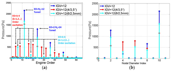
Figure 14.
Frequency spectrum and circumferential wave spectrum comparison of the tuned and two other types of sectional non-uniform mistuned stators: (a) frequency spectrum and (b) circumferential wave spectrum.
For case III, the minimum symmetric periodic number changed from 12 () to 4 (); thus, the quadruplicated frequency appears, which is , and its multiple components in the EO diagram. Similarly, in case IV, EO = 6 and its multiple components appear.
Figure 14b shows the circumferential wave spectrum of the tuned case and sectional non-uniform mistuned stator case III and IV. Compared to the asymmetric mistuned stator cases in Figure 13, sectional non-uniform mistuned stators bring fewer circumferential wave components. Combining Equation (3) with Equation (16), the circumferential wave spectrum of the sectional non-uniform mistuned stator case can be written as:
If , , and , the circumferential wave spectrum of the tuned case can be written as Equation (18). In order to arrange the amplitude from large to small, the formula is arranged from 1 to 4 according to the value of :
Similarly, for mistuned stator case III, , , and the circumferential wave spectrum is:
Additionally, for mistuned stator case IV, the circumferential wave spectrum is:
According to Table 1, when , components in wake excitation and circumferential wave number , which can excite the eleven-order modal resonance of a bladed disk with a nodal diameter of two. The resonance conditions can be described as follows:
The amplitude of excitation force is 1313 Pa, as shown in Table 6.
Table 6.
Comparison of the excitation force amplitudes of three stator structures.
Compared to the tuned case, excitation components with as the fundamental frequency still exist; however, the amplitude of each component decreases significantly. Meanwhile, the number of new frequency components added in sectional non-uniform mistuned stator cases is fewer than in asymmetric mistuned stator cases. Table 6 shows the comparison of excitation amplitude at . Compared to the tuned case, the resonance excitation amplitude of sectional mistuned stator cases III and IV reduced to 40.3% and 72.7%, respectively.
Referring to the resonance conditions in Table 1, with mistuned stator case III, no new component corresponding to resonance condition was created. Additionally, with mistuned stator case IV, and , corresponding to the twelve-order modal resonance of bladed disks appearing.
For the Rotor67 bladed disk in this study, if the number of stator blades was set as , the sectional non-uniform mistuned stator case III: could significantly reduce the amplitude of excitation force at the resonance point without introducing a new resonance frequency.
5. Conclusions
In this study, a Rotor67 bladed disk was developed. Combined with the resonant condition, the bladed disk’s resonance condition has been detailed while considering both model frequency and nodal diameter number. Based on the calculations and analyses of three-dimensional unsteady rotor–stator interference flow fields, the induced flow excitation of tuned and mistuned stator cases towards bladed disks has been studied. The main conclusions are as follows:
- (1)
- The excitation components of rotor–stator interference flow field on a bladed disk can be described by frequency components and circumferential wave components. The main frequency components can be written as , whereas the main circumferential wave components can be written as , among which . Components corresponding to are the main excitation, both for frequency and circumferential wave components, and the amplitude decreases with the increase in .
- (2)
- Referring to the Rotor67 bladed disk in this study, was chosen as the structural period number for stators; flow excitation here will not cause resonance. Through numerical analysis, it was shown that this method can determine the rationality of the stator–structural period without the need for performing numerical simulations of three-dimensional unsteady flow induced by rotor/stator interactions.
- (3)
- Compared with tuned stators, mistuned stators break up the wake energy by changing the topology of the blade. Therefore, the maximum amplitude of the wake excitation component decreases; however, the number of excitation components increases.
- (4)
- Two types of mistuned stators were studied: asymmetric mistuned and sectional non-uniform mistuned stators. Asymmetric mistuned stators decrease the excitation amplitude, although the components may induce resonance increases which renders them unsuitable for application. Sectional non-uniform mistuned stators can significantly reduce the amplitude of excitation without introducing too many new components, which shows potential in suppressing vibrations.
Author Contributions
Conceptualization, H.M., Z.Z. and L.L.; methodology, H.M. and L.L.; software, H.M.; validation, H.M., L.L. and Z.Z.; formal analysis, H.M.; investigation, H.M. and Z.Z.; resources, H.M. and L.L.; data curation, Z.Z.; writing—original draft preparation, H.M.; writing—review and editing, H.M. and L.L.; visualization, H.M.; supervision, H.M.; project administration, H.M. and L.L.; funding acquisition, H.M. and L.L. All authors have read and agreed to the published version of the manuscript.
Funding
This research received no external funding.
Institutional Review Board Statement
Not applicable.
Informed Consent Statement
Not applicable.
Data Availability Statement
Not applicable.
Acknowledgments
The authors would like to thank the guidance and kind advice of Chao Li.
Conflicts of Interest
The authors declare no conflict of interest.
References
- Kielb, J.J.; Abhari, R.S.; Dunn, M.G. Experimental and numerical study of forced response in a full-scaled rotating turbine. In Proceedings of the ASME Turbo Expo 2001: Power for Land, Sea, and Air, New Orleans, LA, USA, 4–7 June 2001. [Google Scholar]
- Sayma, A.I.; Vahdati, M.; Imregun, M. An integrated nonlinear approach for turbomachinery forced response prediction. part I:formulation. J. Fluid Struct. 2000, 14, 87–101. [Google Scholar] [CrossRef]
- Kirkhope, J.; Wilson, G.J. A finite element analysis for the vibration modes of a bladed disc. J. Sound Vib. 1976, 49, 469–482. [Google Scholar] [CrossRef]
- Wang, P.-Y. Research on Vibration Suppression Theory of Bladed Disk of Aeroengine under Fluid Excitation; Beijing University of Aeronautics and Astronautics: Beijing, China, 2014. [Google Scholar]
- Xin, J.-Q. Researches on Typical Problems of Blisk Rotor Vibration in Turbomachinery; Beijing University of Aeronautics and Astronautics: Beijing, China, 2011. [Google Scholar]
- Yao, J.-Y. Forced Response Analysis of Bladed Disk under Fluid Excitation; Beijing University of Aeronautics and Astronautics: Beijing, China, 2010. [Google Scholar]
- Wildheim, S.J. Excitation of rotationally periodic structures. J. Appl. Mech. 1979, 46, 878–882. [Google Scholar] [CrossRef]
- Zhao, Z.; Song, W.; Jin, Y.; Lu, J. Effect of Rotational Speed Variation on the Flow Characteristics in the Rotor-Stator System Cavity. Appl. Sci. 2021, 11, 11000. [Google Scholar] [CrossRef]
- Faller, A.J. An experimental study of the instability of the laminar Ekman boundary layer. J. Fluid Mech. 1963, 15, 560. [Google Scholar] [CrossRef]
- Bayley, F.J.; Owen, J.M. Flow between a Rotating and a Stationary Disc. Aeronaut. Q. 1969, 20, 333–354. [Google Scholar] [CrossRef]
- Owen, J.M. Flow and Heat Transfer in Rotating-Disc Systems; JohnWiley Sons Inc.: New York, NY, USA, 1989; Volume 90, pp. 81–103. [Google Scholar]
- Bréard, C.; Green, J.S.; Imregun, M. Low-Engine-Order Excitation Mechanisms in Axial-Flow Turbomachinery. J. Propuls. Power 2015, 19, 704–712. [Google Scholar] [CrossRef]
- Bréard, C.; Vahdati, M.; Sayma, A.I.; Imregun, M. An Integrated Time-Domain Aeroelasticity Model for the Prediction of Fan Forced Response due to Inlet Distortion. J. Eng. Gas Turbines Power 2002, 124, 196–208. [Google Scholar] [CrossRef]
- Bladh, R.; Zhuang, Q.; Hu, J.; Hammar, J. Leakage-Induced Compressor Blade Excitation due to Inter-Segment Gaps. Asme Turbo Expo Turbine Tech. Conf. Expo. 2012, 44731, 1621–1632. [Google Scholar]
- Meng, Y.; Li, L.; Li, Q.-h. Asymmetry stator mistuned blade design and research. J. Aerosp. Power 2007, 22, 2083–2088. [Google Scholar]
- Meng, Y.; Li, L.; Li, Q.-h. Study on the influence of aerodynamic mistuned on unsteady aerodynamic force of blade. J. Aerosp. Power 2007, 22, 2083–2088. [Google Scholar]
- X, J.-Q.; Wang, J.-J. Forced response characteristic of bladed disk with aerodynamic mistuning. J. Aerosp. Power 2012, 27, 801–810. [Google Scholar]
- Kemp, R.H.; Hirschberg, M.H. Theoretical and Experimental Analysis of the Reduction of Rotor Blade Vibration in Turbomachinery Through the Use of Modified Stator Vane Spacing; NACA: Washington, DC, USA, 1958. [Google Scholar]
- Meng, Y.; Li, L.; Li, Q.-H. Transient analytical method of vane forcing response under stator-rotor wake influence. J. Beijing Univ. Aeronaut. Astronaut. 2007, 22, 2083–2088. (In Chinese) [Google Scholar]
- Yang, J.; Qiao, W.Y.; Hou, W.T.; Wei, Z.J. Numerical study on the stator solidity characteristics of axial turbine element stages. J. Aerosp. Power 2006, 32, 671–674. (In Chinese) [Google Scholar]
- Tan, J.; Wang, X.; Qi, D.; Wang, R. The effects of radial inlet with splitters on the performance of variable inlet guide vanes in a centrifugal compressor stage. Proc. Inst. Mech. Engineers. Part C J. Mech. Eng. Sci. 2011, 225, 2089–2105. [Google Scholar] [CrossRef]
- Liu, J.; Yuan, W.; Hao, X. Experiment on treating block number of non-axisymmetric casing treatment. J. Propuls. Technol. 2009, 30, 434–438. [Google Scholar]
- Gottfried, D.; Fleeter, S. Passive detuning for HCF reduction. In Proceedings of the 38th AIAA/ASME/SAE/ASEE Joint Propulsion Conference & Exhibit, Indianapolis, Indiana, 7–10 July 2002. [Google Scholar]
- Figaschewsky, F.; Giersch, T.; Kühhorn, A. Forced response prediction of an axial turbine rotor with regard to aero-dynamically mistuned excitation. In Proceedings of the ASME Turbo Expo 2014: Turbine Technical Conference and Exposition, Düsseldorf, Germany, 16–20 June 2014. [Google Scholar]
- Sullivan, B.M.; Edwards, B.D.; Brentner, K.S. A subjective test of modulated blade spacing for helicopter main rotors. Am. Helicopter Soc. 2005, 50, 26–32. [Google Scholar] [CrossRef] [Green Version]
- Edwards, B.; Booth, E.R., Jr. Psychoacoustic Testing of Modulated Blade Spacing for Main Rotors; Contractor Report; NASA: Washington, DC, USA, 2002. [Google Scholar]
- Marshall, J.G.; Imergun, M. A Review of Aeroelasticity Methods with Emphasis on Turbomachinery Applications. J. Fluids Struct. 1996, 10, 237–267. [Google Scholar]
- Srinivasan, A.V. Flutter and Resonant Vibration Characteristics of Engine Blades. J. Eng. Gas Turbine Power 1997, 199, 742–775. [Google Scholar] [CrossRef]
- Sadeghi, M.; Liu, F. Investigation of Mistuning Effects on Cascade Flutter Using a Coupled Method. J. Propuls. Power 2007, 23, 266–272. [Google Scholar]
- Spara, K.M.; Fleeter, S. Supersonic turbomachinery rotor flutter control by aerodynamic detuning. J. Propuls. Power 1993, 9, 561–568. [Google Scholar] [CrossRef]
- Hoyniak, D.; Fleeter, S. Forced response analysis of an aerodynamically detuning supersonic turbomachine rotor. J. Vib. Acoust. Stress Reliab. Des. 1986, 108, 117–124. [Google Scholar] [CrossRef]
- Hoyniak, D.; Fleeter, S. The effect of circumferential aerodynamic detuning on coupled bending-torsion unstalled supersonic flutter. J. Turbomach. 1986, 108, 253–260. [Google Scholar] [CrossRef]
Publisher’s Note: MDPI stays neutral with regard to jurisdictional claims in published maps and institutional affiliations. |
© 2022 by the authors. Licensee MDPI, Basel, Switzerland. This article is an open access article distributed under the terms and conditions of the Creative Commons Attribution (CC BY) license (https://creativecommons.org/licenses/by/4.0/).