Featured Application
Mechanical structural parts such as automobile parts made of aluminum alloy that have long-term stable compressive residual stress and require an extremely hard surface.
Abstract
The peening solution treatment was performed on AC4CH aluminum alloy by ultra-high-temperature and high-pressure cavitation (UTPC) processing, and the peening natural aging was examined. Furthermore, peening artificial aging treatment by low-temperature and low-pressure cavitation (LTPC) was performed, and the time course of peening natural aging and peening artificial aging were compared and investigated. It was found that when the AC4CH alloy is processed for an appropriate time by UTPC processing, compressive residual stress is applied and natural aging occurs. In addition, the UTPC processing conditions for peening natural aging treatment with high compressive residual stress and surface hardness were clarified. After peening artificial aging by LTPC processing, the compressive residual stress decreases slightly over time, but the compression residual stress becomes constant by peening natural aging through UTPC treatment. In contrast, it was found that neither natural nor artificial peening natural aging occurs after processing for a short time.
1. Introduction
The mechanism of high-pressure water jet action on materials has been well understood for decades [1]. Shot peening [2,3] and fine particle peening [4] are techniques for mechanically striking surfaces with particles to impart compressive residual stress. Another processing technology modifies surfaces with an abrasive water jet formed by adding an abrasive to water pressurized to about 300 MPa [5,6].
When water jet cavitation (WJC) is irradiated with ultrasonic waves to increase the temperature and pressure, the cavitation has both mechanical and electrochemical affects. This is called multifunction cavitation [7,8] (MFC, PCT Pub. No. W02016/136656, US Registered Patent [9]). WJC has a bubble radius of about 100 μm, and the impact pressure at the time of bubble collapse is about 1000 MPa [10]. In contrast, in the ultrasonic cavitation (UC) used for cleaning, the bubble nuclei originally existing in the water with a radius of several micrometers are irradiated with ultrasonic waves, and the collapse pressure is small, but the temperature at the time of bubble shrinkage is several thousand kelvins [11,12,13]. MFC bubbles have a large radius of about 100 μm, a collapse temperature of several thousand kelvins, and a high collapse pressure of about 1000 MPa. Such bubbles are a feature of WJC and UC. The distribution and unsteady flow of WJC bubble clouds that are changed by sound pressure from incident ultrasonic waves have been clarified analytically and experimentally [14]. Previous studies have developed ultra-high-temperature and high-pressure cavitation (UTPC) obtained by attaching a swirl flow nozzle (SFN) used for water jet peening in air to further increase the bubble size, number of bubbles, temperature, and pressure of MFC [15]. In addition, a photon counting head was used to measure the photons (sonoluminescence) emitted from UTPC, MFC, UC, SFN-WJC, and WJC. The UTPC has the highest emission intensity, number of photons, and bubble interior temperature upon collapse. It was clarified that there is a correlation between the sonoluminescence results and the surface modification results of low-alloy steel [9]. Using these high-temperature and high-pressure bubbles, surface modifications of various metals and ceramics have been carried out.
The foremost use of aluminium casting alloys is in the automotive industry (60% of the tonnage world-wide). These are mainly engine components elaborated from alloys with silicon, most of which also contain at least 3% copper. The main applications outside the automotive industry are in mechanical construction, electrical engineering, transport, household electrical appliances and ironmongery [16]. Studies on the processing and natural aging of aluminum alloys have been also reported. The influence of the stirring pin and pressing tool shoulder on the microstructural softening during friction-stir processing and subsequent natural aging behavior was investigated for a 6061-T6 aluminum alloy [17]. Severe plastic deformation (SPD) can be used to generate ultra-fine-grained microstructures and thus to increase the strength of many materials. Unfortunately, high-strength aluminum alloys are generally hard to deform, which imposes severe limits on the feasibility of conventional SPD methods. The low-temperature equal-channel angular pressing method was used to deform an AA7075 alloy, and the influence of natural aging of a solid solution heat treated AA7075 alloy (prior to SPD) on the microstructure and the mechanical properties after equal-channel angular pressing was studied [18].
In this study, the outermost surface of a material was solution-treated using UTPC processing to raise the temperature to at least 500 °C higher than the equilibrium phase diagram of the aluminum alloy. Then, the elements added to the aluminum alloy formed a supersaturated solid solution and became distributed uniformly. After that, the possibility of T4 treatment, which is a natural aging process that gradually precipitates a Guinier–Preston (GP) zone at room temperature, was examined from the viewpoints of hardness, structural change, corrosion resistance, surface shape, and changes in compressive residual stress over time.
2. Materials and Methods
The specimens were Al-Mg-Si alloy (AC4CH), and its chemical composition is shown in Table 1. Rolled-plate tempered material of 30 mm × 30 mm × 5 mm was cut from the rolled state and used as specimens. Therefore, they were in a state where work hardening remained.

Table 1.
Chemical composition of Al-Mg-Si alloy (AC4CH) (wt%).
UTPC processing aimed at natural aging and low-temperature and low-pressure cavitation (LTPC) processing for comparison were performed on the rolled tempered material. Figure 1 is a schematic diagram of the equipment that performed UTPC and LTPC processing. High-pressure water is injected from a high-pressure pump and generates WJC, which is irradiated with ultrasonic waves from an ultrasonic transducer. The isothermal expansion and adiabatic compression [19,20] of WJC continues when the sound pressure around WJC remains below the break threshold [21] due to changes in the sound pressure of longitudinal waves. This produces high-temperature and high-pressure MFC. Furthermore, when a swirling nozzle is attached to the jet nozzle, the pressure of the jet center is reduced as the swirling flow is generated, the size of WJC increases, and the number of bubbles of WJC also increases due to the decrease of the cavitation number. When this WJC is irradiated with ultrasonic waves, UTPC is generated [15].
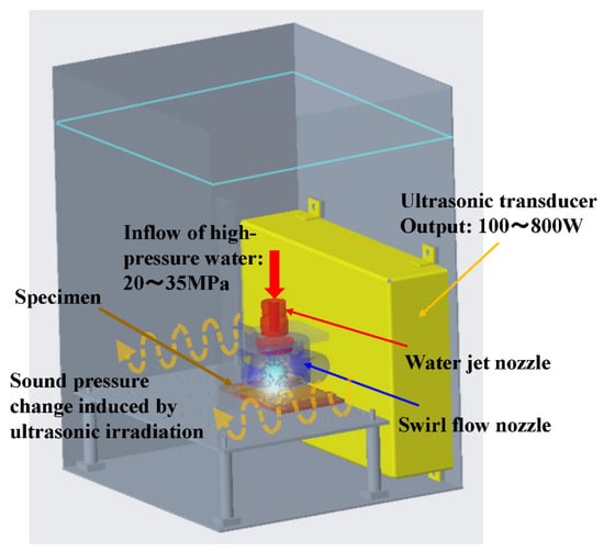
Figure 1.
Schematic diagram of processing equipment for ultra-high-temperature and high-pressure cavitation (UTPC) and low-temperature and low-pressure cavitation (LTPC).
As the study on the cavitation number, there is a report that the formation of cloud cavitation vortex is controlled by the cavitation number in a narrow region similar to the swirling nozzle of this study [22]. According to the calculation of a single bubble using the Rayleigh-Plesset equation, for example, when a sound pressure of 130 kPa due to ultrasonic waves is applied to a WJC with a radius of 100 μm, the bubble expands to the bubble radius of 200 μm and shrinks to 3 μm in a time of 41 μs. The pressure reaches 3700 MPa and the temperature becomes 2.37 × 10⁵ K inside the bubble. However, in fact, at the final stage of contraction, the increase in the bubble temperature is suppressed by chemical reaction heat and heat conduction accompanying the thermal decomposition of steam. In conventional measurement data of sonoluminescence, it is considered that the maximum bubble temperature is 100,000 K. The dynamics of single-bubble and multi-bubble was experimentally investigated using sonoluminescence [23]. It is known that the pressure and temperature achieved inside a bubble during multi-bubble sonoluminescence (MBSL) are much lower than those during single-bubble sonoluminescence (SBSL). In addition, when MFC or UTPC bubbles reach the minimum volume, they flatten in the direction parallel to the material surface, and the bubble part farthest from the surface becomes a piercing form, forming a high-speed jet (microjet) that pierces the material surface. However, the instability in microjet and two bubble interaction were reported [24]. Further studies are needed on the relationship between interactions in multi-bubble and microjet.
The pressure inside a bubble during collapse is mainly determined by the pump discharge pressure, and the temperature inside the bubble is mainly controlled by the ultrasonic output. The UTPC conditions were pump discharge pressure of 35 MPa, the standoff distance of 65 mm between the sample and the water jet nozzle, ultrasonic output of 800 W, and ultrasonic frequency of 28 kHz, whereas the LTPC conditions were pump discharge pressure of 20 MPa, ultrasonic output of 100 W, and ultrasonic frequency of 28 kHz. Here, the ultrasonic mode was selected as the dual mode because it had the highest peening effect in previous studies. The LTPC condition is the so-called peening aging [25] condition, in which the highest compressive residual stress more than −170 MPa can be applied to the AC4CH aluminum alloy. The sound pressure of ultrasonic waves controls the temperature of MFC bubbles. In this study, the sound pressure of ultrasonic output 800W that irradiates the water jet cavitation is 15 mV under the UTPC condition. On the other hand, the sound pressure of the ultrasonic output 100 W is 5 mV under the LTPC condition. These are the values of relative sound pressure measured by the sound pressure sensor (Portable Sonic Monitor: HUS-3, HONDA ELECTRONICS CO., LTD.). The processing time was changed to 2 min, 5 min, 10 min, 20 min, and 30 min to increase the outermost surface temperature to the solution heat temperature and clarify the time required for the solution treatment. Furthermore, to investigate the effect of processing for a longer time, UTPC for 60 min was also performed.
As a method for evaluating the peening natural aging by cavitation, Vickers microhardness measurement (Mitutoyo Corp., HM-210B system), observation and analysis by scanning electron microscope–energy dispersive X-ray spectroscopy (SEM-EDS) performed by a field emission SEM (Hitachi, S-4800), surface roughness measurement, and surface potential (corrosion potential) measurement with a Kelvin force probe microscope (KFM) (Hitachi, AFM5000II) were carried out. In the hardness measurement, the specific locations in the peening region to which the compressive residual stress was imparted were determined, and the change in hardness over time was examined. In addition, 10 points were measured at each processing time under each condition, and the average of 8 points with the maximum and minimum values removed was calculated. In addition, the compressive residual stress applied to the surface was measured by Cr Kα X-ray diffraction (MSF–3 M, Rigaku Corp.) to evaluate the change over time.
Figure 2 shows the principle of cavitation natural aging. As previously discussed, UTPC (micro-forging) is suitable for surface modification of refractory metals, and LTPC is suitable for low-melting-point metals, such as aluminum alloys. When LTPC is applied to an aluminum alloy, the microjet has few hot spots [11] and the temperature inside the bubbles is low, which is appropriate for artificial aging, so it is possible to impart compressive residual stress and artificial aging simultaneously. However, when a low-melting-point metal is processed by UTPC with many hot spots in the microjet, the additive elements of Mg and Si become a supersaturated solid solution at room temperature, but the outermost surface is overheated above the solution temperature. Therefore, Mg and Si are mixed uniformly. After the UTPC stops, a GP zone gradually precipitates due to natural aging, and the compressive residual stress formed by the elastic restraint of the surroundings creates new dislocations, which are entangled with the precipitates and hardened by the Orowan mechanism.
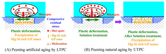
Figure 2.
Schematic diagram of peening artificial aging by LTPC and peening natural aging by UTPC.
3. Results and Discussion
Figure 3 shows photographs of the LTPC processing surface jetted at a fixed point. When fixed-point injection is performed with using the SFN, an erosion region is formed at the injection center, and a peening region is formed around the transition region of the erosion region. In particular, the distribution of the peening region becomes pronounced after processing of 5 min or more. Figure 4 shows the photographs of UTPC processing surface jetted at a fixed point. Compared to LTPC, the peening area is expanded in the peripheral direction. Although the area of the perforated disc-shaped peening region of LTPC is small, the compressive residual stress is higher than that of UTPC, which has a large peening region, due to the peening artificial aging.
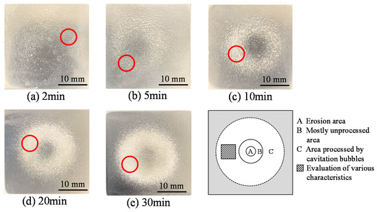
Figure 3.
Surface photographs after LPTC processing (alloy: AC4CH, jet: 20 MPa, UC: 100 W).
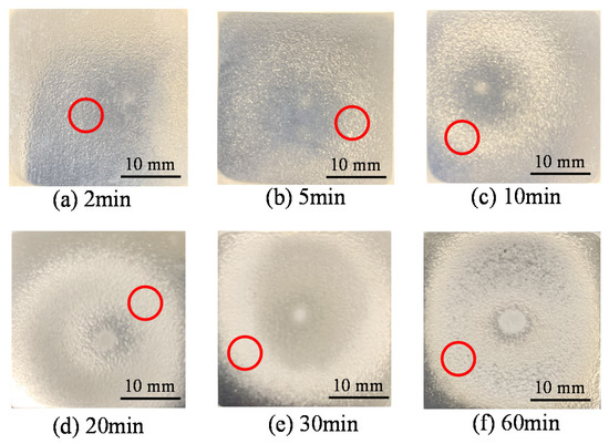
Figure 4.
Surface photographs after UPTC processing (alloy: AC4CH, jet: 35 MPa, UC: 800 W). (○: roughness and hardness measurement area).
Figure 5 shows the changes of surface roughness with processing time in the peening region after UTPC and LTPC processing. Arithmetic mean roughness Ra increases with processing time, but there is no significant difference in surface roughness between UTPC and LTPC up to 20 min. However, from the KFM observation results, the number of peening marks is larger in LTPC than in UTPC, and the surface of LTPC is relatively smooth compared to that of UTPC, but the UTPC surface has many fine irregularities.
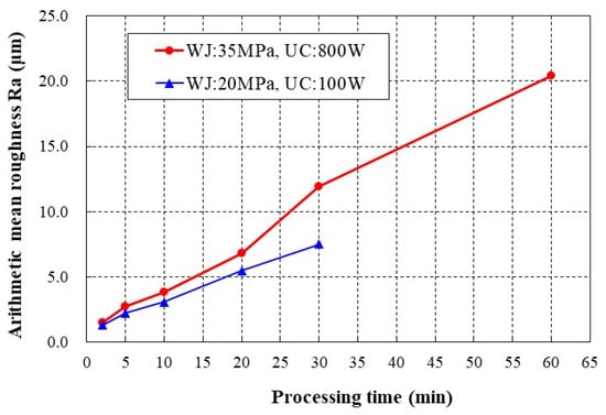
Figure 5.
Change of surface roughness with processing time of LPTC and UTPC (LTPC: jet 20 MPa, UC 100 W; UTPC: jet 35 MPa, UC 800 W) (Evaluation length 5 mm)
The Vickers microhardness of the untreated material was 85.3 HV. Figure 6 shows the time course of hardness after UTPC processing at various times. No increase in hardness was observed after 2 min or 5 min of processing, but an increase in hardness was observed after processing for 10 min or more. The hardness of the material treated for 20 min increased the most. After 20 min of UTPC processing, the hardness reached its maximum value 21 days after processing, and then the hardness decreased and increased again.
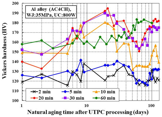
Figure 6.
Relationship between hardness and elapsed time after UPTC processing (WJ: 35 MPa, UC: 800 W) (Average of standard deviation: 2 min 5.9 HV, 5 min 7.5 HV, 10 min 9.9 HV, 20 min 9.5 HV, 30 min 11.2 HV, 60 min 6.9 HV).
The reason the hardness increased after 10 min or more of UTPC processing is as follows. The outermost surface is solution treated by UTPC processing, as shown in Figure 2, and the supersaturated solid solution elements Mg and Si are perfectly mixed in aluminum at the solution temperature. After that, when cavitation stops and the temperature decreases to room temperature, the surface becomes a supersaturated solid solution, and Mg and Si gradually precipitate as GP zones. The surface is plastically deformed by the microjet when cavitation bubbles collapse, and compressive residual stress is imparted. This compressive stress causes dislocations on the surface, and the dislocations are trapped in the precipitates and hardened by the Orowan mechanism. The reason the hardness of material processed for 20 min and 30 min decreases at first and then increases again is thought to be a result of natural aging as the structure changes from GP I phase to GP II phase and θ’ phase. It is considered that the compressive residual stress generated causes new dislocations that are related to the pinning effect on the precipitate.
In contrast, it can be recognized that after 60 min of processing, unlike the material processed for 20 min, hardening does not occur immediately after processing. The hardness immediately after processing was about 160 HV, which was about the same as that for the LTPC 20-min processing and LTPC 30-min processing shown in Figure 7. However, after 60 days, the 60-min processed surface was hardened to 183 HV.
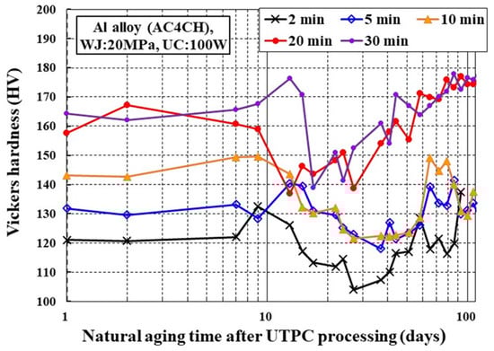
Figure 7.
Relationship between hardness and elapsed time after LTPC processing. (WJ: 20 MPa, UC: 100 W) (Average of standard deviation: 2 min 7.7 HV, 5 min 6.6 HV, 10 min 8.5 HV, 20 min 8.4 HV, 30 min HV, 60 min 8.4 HV).
Al-0.62% Mg-0.39% Si alloy was quenched in water after solution treatment and naturally aged. The hardness increased by 12 HV on 1 day after solution treatment and quenching, and an increase by 22 HV on day 11 has been reported [26]. Because the chemical composition of Al-Mg-Si is different between these two cases, a simple comparison cannot be made, but in the UTPC processing of this study, after the solution temperature was reached and the cavitation stopped, specimens were rapidly cooled in water, similar to quenching. However, the decisive difference between natural aging by heat treatment and peening natural aging by UTPC is the presence of compressive residual stress after quenching of peening natural aging on the surface. When a GP zone is formed by natural aging, dislocations occur due to compressive residual stress, and the hardness increase is larger than that of natural aging by heat treatment. In fact, as shown in Figure 6 the hardness of the material processed by UTPC for 20 min increased by about 50 HV from 1 day to 9 days later.
The compressive residual stress after LTPC processing (20 MPa, 100 W, 20 min) was −170.6 MPa, and the compressive residual stress after UTPC processing (35 MPa, 800 W, 20 min) was −133.67 MPa [25]. Figure 7 shows the change in hardness over time after LTPC processing (20 MPa, 100 W, 20 min), which gives the highest compressive residual stress. Unlike the case of UTPC, hardness did not increase over time. This is because the surface did not reach the solution temperature during LTPC processing, and peening natural aging did not occur. Similar to the results for UTPC processing in Figure 6, the material hardness of each LTPC processing time tended to decrease once and increase again. This is the result of a balance between changes in precipitates and the formation of new dislocations due to compressive stress after peening artificial aging, which has the highest compressive residual stress during processing, although it has not reached the solution temperature.
A qualitative SEM-EDS line analysis of the region of interest (ROI (Regions of Interest): the function that creates a window by specifying the X-ray energy range of interest in the spectrum) on the surface after UTPC and LTPC processing was carried out. Here, many-line qualitative analysis at 100,000 magnification was performed on the surface of specimens 1 day and 6 days after UTPC processing. Figure 8 shows the frequency distribution of the ROI analysis intensity of each Al, Mg, and Si concentration. The horizontal axis is the analytical intensity of various elements, and the vertical axis is the frequency distribution of the analytical intensity, showing the concentration distribution of various elements. It can also be recognized that the Mg concentration and Si concentration distribution were broader after 6 days in comparison with that after 1 day. When a GP zone is formed due to fluctuations in the concentrations of solute elements of Mg and Si by spinodal decomposition, the concentration of solvent elements changes to the same extent that the concentration of solute elements fluctuates. However, the fact that the spread of the Mg concentration distributions after 6 days of UTPC and 1 day of LTPC in Figure 8b are large, and the spread of solvent element Al concentration distributions are remarkably large in Figure 8a. This indicates that phase separation occurs due to spinodal decomposition in natural aging, which is consistent with the result of the increase in hardness in Figure 6. Furthermore, according to the result of qualitative analysis of ROI by SEM-EDS line analysis of the surface of a specimen 1 day after LTPC, the surface temperature did not reach the solution temperature. Therefore, phase separation occurred as it does without processing, and the solvent element Al concentration distribution is as wide as that in the specimen 6 days after UTPC.
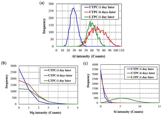
Figure 8.
Frequency distribution of Mg and Si concentrations obtained from SEM-EDS line analysis 6 days after UTPC processing: (a) Al; (b) Mg; (c) Si. (WJ: 35 MPa, UC: 800 W, 20 min).
Figure 9a,b shows the shape image and corrosion potential image of the mirror-polished surface before processing, respectively, as measured by KFM. The shape image is flat due to mirror polishing, and the potential image has no bias and a uniform potential distribution.
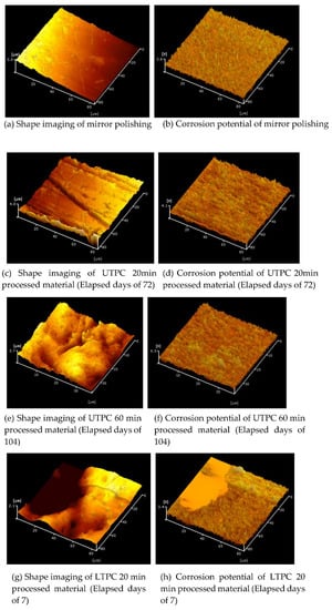
Figure 9.
Results of shape imaging and corrosion potential measurement of UTPC and LTPC processed material by Kelvin force probe microscope (KFM).
Figure 9c,d shows the KFM measurement results 72 days after UTPC processing of a specimen for 20 min; at this point, the hardness was starting to increase again. Although unevenness after processing is observed in the shape image, the potential image does not have a particularly biased distribution. In addition, the surface was leveled by raising the surface temperature to a level that generated solution treatment, and no remarkable peening marks were observed. Figure 9e,f provides the KFM measurement results after 104 days, when the hardness gradually increased after UTPC (WJ: 35 MPa, UC: 800 W, 60 min) processing. Although large irregularities are observed in the shape image, the potential image does not have a particularly biased distribution. In contrast, Figure 9g,h shows the KFM measurement results 7 days after LTPC processing of a specimen, which applies the highest compressive residual stress. A dent, which is considered to be a peening mark, is observed in the shape image. The surface potential at the peening mark is lower than that in the other regions. Further, the reason the peening marks were observed is that the surface did not reach the solution temperature and surface homogenization did not occur due to the lower processing temperature.
Table 2 gives the surface potential results for the various specimens. KFM can measure the work function, which is a measure of the ease with which electrons are emitted from the surface. Because oxidation involves the transfer of electrons, the higher the surface potential, the higher the corrosion resistance. Among aluminum alloys, AC4CH without processing has high corrosion resistance, and its surface potential after mirror polishing is as high as 1200 mV. The surface potential of special steel does not exceed 1000 mV, even after MFC processing [27]. Even if the aluminum alloy is mirror-polished, a passivation film is immediately formed and corrosion resistance is maintained. The surface potential of the specimen subjected to LPTC processing, which imparts the highest compressive residual stress, is almost the same as that of the as-received specimen after mirror polishing. UPTC processing, which causes peening natural aging, produced a decreased surface potential with 20 min of processing and increased potential with 30 min and 60 min of processing. After the outermost surface reaches the solution temperature and is subjected to the solution treatment by UTPC, precipitates such as GP zones are formed on the surface. The disparate surface potential results for the UTPC specimens are probably due to different formation states of these precipitates being created by different processing times (20 min vs. 30 min and 60 min). In the 60-min processed material, no change in surface potential was observed between 41 days and 104 days.
Table 2.
Surface potential of aluminum alloy (AC4CH) by various processing.
In the UTPC 20-min processing and 30-min processing of the present study, the initial surface roughness was small (Ra: 0.1 μm); therefore, the surface was heated to the solution temperature, and the peening solution process was possible. In contrast, in UTPC 60-min processing, peening solution processing was performed up to 30 min; however, as the surface roughness increases with processing, the microjet impingement is not always vertical, and despite processing under UTPC conditions, UTPC processing does not occur. This is because the processing was performed at low temperature and low pressure. In addition, as can be seen from the shape image of Figure 9e,f due to long-term UTPC processing, high-temperature processing was not possible because the specific surface area increased and the ratio of heat dissipation to water increased rather than the heat input to the alloy interior. Therefore, it is probable that in the latter half of the 60-min processing, the peening artificial aging was performed by the pseudo-LTPC processing from the state where the solution was once processed. Therefore, as shown in Figure 6, hardening by natural aging did not occur after processing.
In UTPC and LTPC processing, the temperature of a metal surface is determined by the balance among heat input to the surface from a large number of cavitation bubbles with hot spots, convective heat dissipation from the surface to water, and heat dissipation due to heat conduction inside the metal. However, it is difficult to measure directly. Therefore, it is carried out by estimating the bubble temperature from the emission intensity (measurement of the number of photons per unit time) at the time of bubble collapse [9] and the temperature estimation is carried out by the structure change based on the equilibrium phase diagram after processing. For example, when UTPC processing is performed on Cr-Mo steel, it has been confirmed that spherical cementite that changes its structure at 500 °C or higher is formed just below the surface [28]. Therefore, it is considered that the surface temperature of AC4CH has reached the solution temperature in the UTPC treatment of this study.
Figure 10 shows the values of compressive residual stress applied to the surface immediately after UTPC and LTPC processing and after a long period of time. The compressive residual stress after 7 days of LPTC 20-min processed material is the highest at −171 MPa; however, after 141 days, it drops to the same level as UTPC 20-min processed material. However, the compressive residual stress of the UTPC 20-min processed material after 7 days is −134 MPa, which is not higher than that of the LPTC 20-min processed material, but the compressive residual stress does not decrease much even after 175 days. The compressive residual stress is reduced to −100 MPa or less in the UTPC 30-min processed material and UTPC 60-min processed material that have passed for a long time. The stability of the compressive residual stress of the UTPC peening natural aging material (UTPC 20 min) is superior to that of the LTPC peening artificial aging material (UTPC 20 min). With the artificial peening aging by LTPC, a compressive residual stress of −100 MPa or more can be applied even in a short time of 2 min, and as shown in Figure 7, a hardness of 120 to 140 HV can be obtained. Considering the decrease of compressive residual stress applied by the peening artificial aging for a long time, it can be judged that short-time processing is sufficient for peening artificial aging treatment by LTPC. Regarding the surface hardness, both the peening natural aging material by UTPC and the peening artificial aging material by LTPC reached almost 180 HV and achieved the same level of hardness after 100 days or more with longer-term processing of 20 min or more. From the viewpoint of corrosion resistance, the peening naturally aged material (UTPC 30 min) by UTPC is superior. From the above results, it is necessary to properly use peening natural aging and peening artificial aging depending on the intended use of the AC4CH alloy.
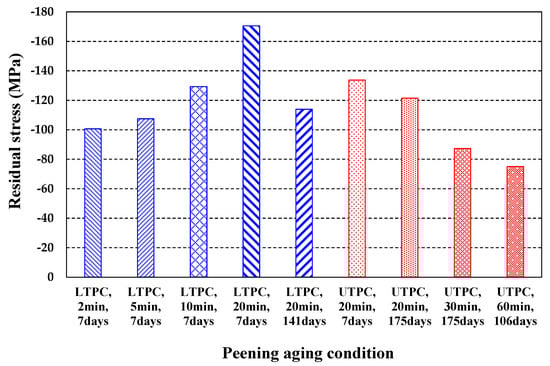
Figure 10.
Aging variation of compressive residual stress of LTPC and UTPC.
4. Conclusions
Peening solution treatment was performed on AC4CH by UTPC processing to investigate peening natural aging. Furthermore, peening artificial aging treatment by LTPC was carried out to examine the change over time of peening natural aging and peening artificial aging, and the following findings were obtained:
(1) When the AC4CH alloy is processed for an appropriate time by UTPC processing, compressive residual stress is applied and natural aging occurs.
(2) The UTPC processing conditions of peening natural aging treatment to create a high surface compressive residual stress, surface hardness, and corrosion resistance were clarified.
(3) After artificial aging by LTPC treatment, the compressive residual stress decreases slightly with the passage of time, but the compressive residual stress is stabilized by peening natural aging by UTPC treatment.
(4) Processing for a short time does not cause peening natural aging by UTPC.
Author Contributions
All authors contributed to the paper either during the writing or editing phases. All authors made a substantial contribution to this research. Planning of research method and evaluation method, T.Y., M.I. (Masataka Ijiri) and S.K.; cavitation processing, M.I. (Masayoshi Iwamoto), T.Y. and M.I. (Masataka Ijiri); hardness measurement and surface roughness measurement, M.I. (Masayoshi Iwamoto); KFM measurement, T.O. and F.K.; measurement of compression residual stress, S.K. All authors have read and agreed to the published version of the manuscript.
Funding
This research was supported in part by JSPS KAKENHI Grant Number 19K04110 (Grant-in-Aid for Scientific Research (C)) and by the Light Metal Educational Foundation, Inc.
Data Availability Statement
Data is contained within the article. The data presented in this study are available on request from the corresponding author.
Conflicts of Interest
The authors declare no conflict of interest.
References
- Summers, D.A. Waterjetting Technology; E&FN Spon: London, UK, 1995; ISBN 9780419196600. [Google Scholar]
- Kim, Y.J.; Bae, D.H.; Kim, Y.J. The Improvement of High Cycle Fatigue Properties of AC4CH Alloy with Shot Peening Treatment. Key Eng. Mater. 2005, 297-300, 1919–1924. [Google Scholar]
- Gao, Y.K.; Wu, X.R. Experimental investigation and fatigue life prediction for 7475-T7351 aluminum alloy with and without shot peening-induced residual stresses. Acta Mater. 2011, 59, 3737–3747. [Google Scholar] [CrossRef]
- Kikuchi, S.; Nakamura, Y.; Nambu, K.; Ando, M. Effect of shot peening using ultra-fine particles on fatigue properties of 5056 aluminum alloy under rotating bending. Mater. Sci. Eng. 2016, A652, 279–286. [Google Scholar] [CrossRef]
- Hashish, M. Characteristics of surfaces machined with abrasive-waterjets. J. Eng. Mater. Technol. 1991, 113, 354–362. [Google Scholar] [CrossRef]
- Hashish, M. A modeling study of metal cutting with abrasive waterjets. J. Eng. Mater. Technol. 1984, 106, 88–100. [Google Scholar] [CrossRef]
- Yoshimura, T.; Tanaka, K.; Yoshinaga, N. Development of mechanical-electrochemical cavitation technology. J. Jet Flow Eng. 2016, 32, 10–16. [Google Scholar]
- Yoshimura, T.; Tanaka, K.; Yoshinaga, N. Nano-level material processing by multifunction cavitation. Nanosci. Nanotechnol. Asia 2018, 8, 41–54. [Google Scholar] [CrossRef]
- Yoshimura, T.; Maeda, D.; Ogi, T.; Kato, F.; Ijiri, M. Sonoluminescence from ultra-high-temperature and high-pressure cavitation and its effect on surface modification of Cr-Mo steel. Global J. Technol. Optim. 2020, 11. [Google Scholar] [CrossRef]
- Summers, D.A.; Tyler, L.J.; Blaine, J.; Fossey, R.D.; Short, J.; Craig, L. Consideration in the design of a waterjet device for reclamation of missile casings. In Proceedings of the Fourth U.S. Water Jet Conference, University of California, Berkeley, CA, USA, 26 August 1987; pp. 82–89. [Google Scholar]
- Gompf, B.; Gunther, R.; Nick, G.; Pecha, R.; Eisenmenger, W. Resolving sonoluminescence pulse width with time-correlated single photon counting. Phys. Rev. Lett. 1997, 79, 1405–1408. [Google Scholar] [CrossRef]
- Yasui, K. Fundamentals of acoustic cavitation and sonochemistry. In Theoretical and Experimental Sonochemistry Involving Inorganic Systems; Ashokkumar, P.M., Ed.; Springer: Berlin/Heidelberg, Germany, 2011; Chapter 1; pp. 1–29. [Google Scholar]
- Lorimer, J.P.; Mason, T.J. Applications of ultrasound in electroplating. Electrochem 1999, 67, 924–930. [Google Scholar] [CrossRef]
- Peng, G.; Shimizu, S. Progress in numerical simulation of cavitating water jets. J. Hydrodyn. 2013, 25, 502–509. [Google Scholar] [CrossRef]
- Yoshimura, T.; Tanaka, K.; Ijiri, M. Nanolevel surface processing of fine particles by waterjet cavitation and multifunction cavitation to improve the photocatalytic properties of titanium oxide. IntechOpen Cavitation 2018. [Google Scholar] [CrossRef]
- Vargel, C. Corrosion of Aluminum, Chapter A.3—The Metallurgy of Aluminium; Elsevier: Amsterdam, The Netherlands, 2004; pp. 23–57. [Google Scholar] [CrossRef]
- Woo, W.; Choo, H.; Brown, D.W.; Feng, Z. Influence of the Tool Pin and Shoulder on Microstructure and Natural Aging Kinetics in a Friction-Stir-Processed 6061–T6 Aluminum Alloy. Metall. Mater. Transac. A 2007, 38A, 69–76. [Google Scholar] [CrossRef]
- Fritsch, S.; Wagner, M.F.X. On the Effect of Natural Aging Prior to Low Temperature ECAP of a High-Strength Aluminum Alloy. Metals 2018, 8, 63. [Google Scholar] [CrossRef]
- Rayleigh, L. On the pressure developed in a liquid during the collapse of a spherical cavity. Philos. Mag. 1917, 34, 94–98. [Google Scholar] [CrossRef]
- Plesset, M.W. The dynamics of cavitation bubbles. J. Appl. Mech. 1949, 16, 277–282. [Google Scholar] [CrossRef]
- Atchley, A.A. The Blake threshold of cavitation nucleus having a radius-dependent surface tension. J. Acoust. Soc. Am. 1988, 85, 152–157. [Google Scholar] [CrossRef]
- Mitroglou, N.; Stamboliyski, V.; Karathanassis, I.K.; Nikas, K.S.; Gavaises, M. Cloud cavitation vortex shedding inside an injector nozzle. Exp. Therm. Fluid Sci. 2017, 84, 179–189. [Google Scholar] [CrossRef]
- Lauterborn, W.; Kurz, T.; Geisler, R.; Schanz, D.; Lindau, O. Acoustic cavitation, bubble dynamics and sonoluminescence. Ultrason. Sonochem. 2007, 14, 484–491. [Google Scholar] [CrossRef] [PubMed]
- Xiong, S.; Tandiono, T.; Ohl, C.D.; Liu, A.Q. Bubble pinch-off and breakup due to instability in microjetting. In Proceedings of the 17th International Conference on Miniaturized Systems for Chemistry and Life Sciences, Freiburg, Germany, 27–31 October 2013; pp. 71–73. [Google Scholar]
- Yoshimura, T.; Ijiri, M.; Shimonishi, D.; Tanaka, K. Micro-forging and peening aging produced by ultra-high-temperature and pressure cavitation. Int. J. Adv. Technol. 2019, 10, 277. [Google Scholar] [CrossRef]
- Hatta, H.; Tanaka, H.; Matsuda, S.; Yoshida, H. Effects of Mg, Si contents and natural aging conditions on the bake hardenability of Al–Mg–Si alloys. J. Jpn. Inst. Light Metals 2004, 54, 412–417. [Google Scholar] [CrossRef][Green Version]
- Ijiri, M.; Yoshimura, T. Sustainability of compressive residual stress on the processing time of water jet peening using ultrasonic power. Heliyon 2018, 4, e00747. [Google Scholar] [CrossRef] [PubMed]
- Ijiri, M.; Yoshimura, T. Evolution of surface to interior microstructure of SCM435 steel after ultrahigh-temperature and ultra-high-pressure cavitation processing. J. Mater. Process. Technol. 2018, 251, 160–167. [Google Scholar] [CrossRef]
Publisher’s Note: MDPI stays neutral with regard to jurisdictional claims in published maps and institutional affiliations. |
© 2021 by the authors. Licensee MDPI, Basel, Switzerland. This article is an open access article distributed under the terms and conditions of the Creative Commons Attribution (CC BY) license (http://creativecommons.org/licenses/by/4.0/).