1. Introduction
In the past three decades, high-power ultrashort pulse lasers have been significantly improved with the rapid development of femtosecond technology and chirped pulse amplification (CPA) [
1]. Several petawatt ultrashort pulses are currently available at petawatt-class laser facilities [
2], such as APOLLON [
3] and the extreme light infrastructure (ELI) facilities [
4], etc. The duration of the ultrashort pulse reaches tens of femtoseconds, and the focused light intensity is up to 10
21 W/cm
2 [
3], providing extreme physical conditions for various high-energy physics, including fast ignition of the compressed inertial fusion targets, laser-driven particle acceleration, and diagnostics for high-energy-density physics [
5,
6,
7,
8]. In addition to the power density, the physical results of the laser–plasma interaction are strongly dependent on the temporal profile of the high-power laser pulse. Nevertheless, the undesired temporal noises are always in existence accompanied by the amplified spontaneous emission, parametric fluorescence, and temporal phase modulation during the process of CPA or optical parametric chirped pulse amplification (OPCPA) [
9]. These temporal noises appear as the pulse pedestals, coherent wings, and leading edge of the main pulse [
10], and even strong pre-pulses, interacting with the target prior to the main pulse and eventually resulting in unsatisfactory experimental results. To suppress the temporal noises of the pulses, various of pulse-cleaning techniques have been reported, including saturable absorber (SA) [
11], cross-polarized wave generation (XPW) [
12], Fourier-filtering [
13], picosecond optical parametric amplification (ps-OPA) [
14] applied before compression, frequency doubling by second harmonic generation (SHG) [
15], and plasma mirrors (PMs) [
16,
17,
18] applied after compression.
Among these methods, PMs exhibit an excellent pulse-cleaning performance for high-power ultrashort pulses. It can effectively and directly suppress all pulse noise after compressing under ultra-high laser intensity. The temporal contrast enhancement is the ratio between the reflectivity of the PM and cold reflectivity, and usually 2–3 orders of magnitude. To evaluate the performance of PMs, the measurement of the reflectivity, beam quality, and temporal contrast enhancement are typically necessary. The reflectivity and beam quality can be easily obtained by calorimeters and cameras. However, the temporal contrast enhancement measurement is complicated and challenging, especially in an online, high-energy physics experiment, owing to the characteristics of single-shot usage.
In most PM experiments, the methods of the temporal contrast measurement are based on the delay-scan third-order cross-correlator [
19,
20,
21,
22,
23], such as Sequoia, which is used for precise temporal contrast measurement with a dynamic range of ~10
10 and a resolution of ~one-hundred-femtoseconds. However, delay-scan methods require a lot of shots with the given repetition rate and cannot be used in a single-shot experiment. Meanwhile, the multiple shots undoubtedly increase the complexity and instability of the measurement. For most single-shot measurement methods, the low dynamic range (<10
6) is far from meeting the application requirements (>10
9) for high-power ultrashort pulses. One typical research reported by Yongzhi Wang et al. was that they successfully measured a temporal contrast of >10
10 for a single-shot pulse in 2014 [
24], which achieves an improvement by several orders of magnitude. However, the method is also complicated with a relatively high cost. The enhancement measurement requirement of 10
2–10
3 of a PM is not worthwhile making big cost to achieve the single-shot temporal contrast measurement of 10
12 or even better. Thus, it is important to develop a convenient single-shot temporal contrast enhancement measurement of PMs.
In recent years, pulse chirp has been widely applied to the spatiotemporal measurement of various ultrashort phenomena. The group velocity dispersion (GVD) of a chirped pulse leads to the continuous queuing of wavelengths in the time domain. Benefiting from it, it is very suitable for the measurement of pulse or plasma with ultrafast response, such as the spatiotemporal measurement of ultrashort laser pulse [
25], laser-generated fast electron measurement [
26], etc. In the previous research, Doumy G et al. proposed the explanation of the measurement of the temporal chirped pulse profile by its spectrum [
27]. Using a 1.1-ps chirped pulse, the spectral phase and temporal reflectivity after the PM were obtained within a single shot. Indeed, the potential of a chirped pulse could be further exploited for the temporal contrast enhancement measurement of PMs.
In this work, we focus on the detailed research of a single-shot method for measuring the temporal contrast enhancement of a PM. It relies on a single-shot measurement of the reflective spectrum of a spatiotemporally overlapped chirped pulse (SOCP), with the igniting pulse producing a PM. We analyzed and estimated the temporal contrast enhancement measurement capability by SOCP, and verified the feasibility by experiments. The experimental results show that the temporal contrast enhancement of a PM in a hundred picosecond scale can be obtained conveniently and accurately.
2. Method for Spatiotemporally Overlapped Chirped Pulse
The plasma mirror is a layer of dense plasma induced by the interaction between an intense laser pulse and target. Generally, the target of the PM is an antireflection (AR) coated glass plate for obtaining the maximum temporal contrast enhancement. When the intense laser pulses shoot onto the target, the low-intensity pedestal and prepulses are transmitted due to the AR coating. When the high-intensity main pulse arrives, the AR-coated target is rapidly ionized and generates dense plasma by tunneling and electronic avalanche ionization. Once the plasma reaches above the critical density and forms the PM, it changes rapidly from initial high transmission to high reflection, resulting in a temporal reflectivity difference between the high-intensity main pulse and low-intensity prepulses. Thus, the temporal contrast enhancement is determined by the contrast between plasma reflectivity and cold reflectivity.
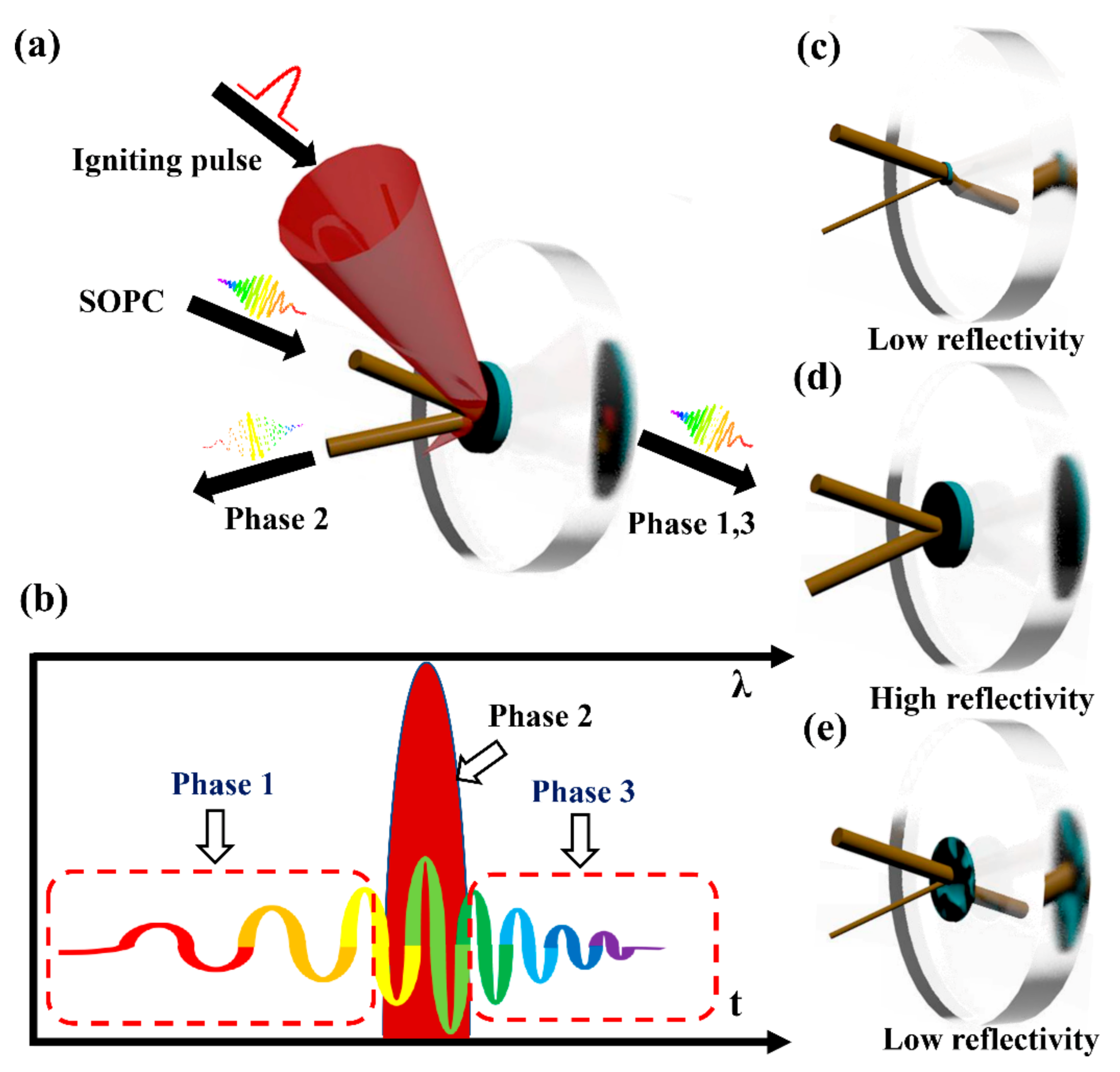
Considering the characteristics of the PMs above, the SOCP is suitable for obtaining the time-resolved reflectivity difference of PMs. Due to the continuous queuing of wavelengths, the spectral profile of SOCP is strongly modulated by PMs and the spectrum contains the temporal reflectivity information of PMs. The concept of SOCP is shown in
Figure 1a. A high-power ultrashort pulse, defined as the igniting pulse, is focused on the AR-coated target of the PM. A SOCP is shot on the AR-coated target as probe pulse. For ensuring the igniting pulse is overlapped within the duration of the chirped pulse in the time domain, a delay line is set to adjust the relative delay between igniting pulse and SOCP.
Figure 1b shows the temporal diagram of SOCP and igniting pulse. The red part represents the igniting pulse and the color part represents the various wavelength components queued continuously in the time domain of SOCP. The duration of a SOCP is much longer than that of the igniting pulse. According to the delay of different wavelength components relative to the igniting pulse, the whole process can be divided into three phases, as shown in
Figure 1c–e. In phase 1 (
Figure 1c), the main pulse of the igniting pulse has not yet arrived at the AR-coated target and a PM has not been generated. The AR-coated target shows extremely low reflectivity, resulting in the wavelength components arrived already from the SOCP after they pass through the target. During phase 2 (
Figure 1d), the strong intensity main pulse arrives and rapidly produces a layer of dense plasma. When plasma reaches the critical density, the PM is completely formed and works as a mirror with ultrahigh reflectivity. The wavelength component corresponding to the chirped pulse temporally overlapped with the PM cannot pass through critical density, and is therefore reflected by the PM. In phase 3 (
Figure 1e), the PM vanishes, and the surface of the AR-coated target has been damaged. The target shows low reflectivity again, and the rest of the wavelength components of the chirped pulse pass through or are scattered.
The rapid change in reflectivity of the PM leads to the different reflectivity of the igniting laser at different phases. Only the wavelength components that temporally overlapped the duration of the PM can be highly reflected and collected into a spectrometer. Thus, the temporal reflectivity information of the PM is included in the recorded spectrum
of the reflected SOCP. Subtracting the background spectrum
from the recorded spectrum
and divided by the original spectrum
, the spectral reflection efficiency profile of the SOCP is obtained. According to the chirp rate
, the spectral profile can be converted into temporal profile
, representing the temporal reflectivity profile of the PM. The temporal profile
can be written as Equation (1). As mentioned above, the temporal contrast enhancement of the PM is the ratio between the plasma reflectivity of the PM and cold reflectivity, which is equal to the contrast of the temporal reflectivity profile. Thus, by spectral measurement of the reflected SOCP, the temporal contrast enhancement of the PM can be directly and conveniently acquired with a single-shot measurement.
In addition, the temporal measurement resolution could be controlled by adjusting the chirp of the SOCP. The temporal resolution is proportional to the chirp rate. The relationship can be written as Equation (2). The temporal resolution of temporal contrast enhancement is equal to the product of the chirp rate of the SOCP and the spectral resolution of the spectrometer. For example, the spectral resolution of the spectrometer in 818.5 nm is about 0.157 nm with a chirp rate of 25 ps/nm. Thus, the temporal resolution is 3.925 ps. To further improve the temporal resolution of this method, one feasible way is to using a higher spectral resolution spectrometer. Moreover, another direct and recommended way is to adjust the chirp rate of the SOCP, usually through grating or a chirped mirror. Obviously, the latter is more attractive for tuning and operation.
3. Experiment and Discussion
3.1. Experiment Setup of SOCP System
To demonstrate the validity of this method, we built up an experimental platform by using the front end of an SG-II 5PW laser system in the National Laboratory on High Power Laser and Physics [
28], which provides an OPCPA-based ultrashort high-power laser. Its wavelength ranges from 750 to 850 nm. In order to obtain the temporal contrast enhancement in a hundred picosecond domain, the chirp rate is selected as 25 ps/nm, corresponding to a pulse duration of 2.5 ns.
The experimental setup is shown in
Figure 2. The OPCPA system provides broadband pulse at the central wavelength of 808 nm, with more than 110 mJ energy at a 1 Hz repetition rate. The laser is divided into two beams, one is compressed to 30 fs as the igniting laser with a double-pass grating pair compressor and another uncompressed OPCPA laser is used as the SOCP. In the optical path of the SOCP, a delay line is set for synchronization. By altering the delay, the igniting pulse can be covered in duration of the SOCP. Moreover, a removable mirror (M1) is inserted into the optical path to record the initial spectrum. For subsequent separation, the SOCP and igniting pulse should be in different polarization. A polarization conversion system with several mirrors is used to convert the igniting pulse from P-polarization to S-polarization while the SOCP is still P-polarized. One calorimeter is set after sampling beam splitter 1 (SBS1) to measure the energy of the igniting pulse. The SOCP and igniting pulse were combined through the polarizing beam splitter (PBS) and inserted into a vacuum container in coaxial.
After that, a pair of 100 mm focal length off-axis parabolic mirrors (OAP1 and OAP2) are used for focusing and collimating, separately. The plate target of a PM using fused silica material with anti-reflection coating (cold reflectivity is ~5‰) is placed at a certain position for enough peak intensity with 45° of incident angle. The beam radius of the igniting pulse on the target is about 50–100 microns. All elements are placed in a vacuum container with a vacuum of 10−3 Pa. The output laser reflected by the PM enters the measurement system through another window. Because the SOCP and the igniting pulse are mixed in the output laser after the PM, which would affect the spectral profile, a Glan–Taylor prism (GTP) is used to separate the igniting pulse and SOCP before the spectrometer (Oceanhood, China, XS11639). The p-polarized SOCP travels through a GTP and is collected into the spectrometer for recording the spectrum.
In addition to verifying the feasibility of single-shot measurement of the SOCP, the efficiency and beam quality needs to be monitored, proving that the SOCP does not affect the physical properties of the PM. Two CCD cameras (Visiyun, China, EHD04MB-GE) and two calorimeters (Ophir, Israel, PF50BF-C) are used for recording the pattern and input–output energy of the separated igniting pulse. Sampling beam splitter 2 (SBS2) is used for sampling a small part of the igniting pulse into CCD cameras, and a 400 mm focal length achromatic lens for focusing the igniting pulse.
Before the single-shot measurement is taken, off-line test and calibration are required. The first step is to determine the synchronization of the igniting pulse and SOCP. A photoelectric probe (Thorlabs, United states, DET025AL/M) placed in front of the vacuum container is used to obtain the temporal signal of two pulses, which are displayed on the oscilloscope (Tektronix, United states, TDS684C). For raising the accuracy, we introduced another femtosecond pulse as the reference to avoid signal crosstalk near synchronization in the experiment. The inborn temporal difference was 3.76 ns. By deducting an extra 3.76 ns of the measured reference from the SOCP, the synchronization of the igniting pulse and SOCP was obtained. We selected the appropriate attenuation ratio for the two channels of laser respectively, so that two signals appear on the oscilloscope with appropriate amplitude. The wide signal is the SOCP and the narrow one is the igniting pulse. Regarding the signal image on the oscilloscope, constantly and carefully adjust the delay until two signals overlap. According to the test results, the accuracy should be within 0.05 ns, and adjusting the delay line so that the 30 fs igniting pulse is in the range of 2.5 ns chirped pulse can satisfy the needs of the measurement. The second step is to ensure the total coaxiality, as any spatial deviation at the PM position may lead to experimental failure. The coaxiality is adjusted by judging the patterns on the far-field and near-field CCD cameras with two pulses. The third step is to accurately rotate the GTP, matching the polarization direction and completely separating the igniting pulse and SOCP. Similarly, the adjusting of GTP is realized by judging the intensity variation of two pulses on a CCD camera. The last step is to calibrate the energy measurement. The key is to calibrate the system efficiency between the two energy measurement positions of the calorimeters in
Figure 2. The AR-coated target of the PM is replaced by a silver mirror considered to be close to 100% high reflectivity. Without amplification, a power meter (Thorlabs, United states, PM100USB) is used to calibrate the efficiency, which is considered to be the same as under amplification. The two calorimeters have the same configuration and test performance. In this way, the PM efficiency is equal to the output energy divided by the input energy, and then divided by the system efficiency.
After all of the above offline tests are completed, the temporal contrast enhancement measurement experiment can be carried out. According to the Equation (1), the initial spectrum
and background spectrum
of the SOCP should be recorded for spectral data processing. Using the same spectrometer after the background filtering, we first recorded the initial spectrum
at the input spectrometer position in
Figure 2. Then, we blocked the optical path of the SOCP, and recorded the background spectrum
by the same spectrometer placed at the output spectrometer position in
Figure 2. After that, we recorded the spectrum
of the reflected SOCP. Moreover, considering the possible spectral modulation by optical components in the system, we tested the spectra of the two measurement positions without amplification. The results showed no spectral modulation, indicating that all the spectral modulation of the SOCP in an online experiment should only come from the PM, rather than the optical components in the system.
3.2. Results and Discussion
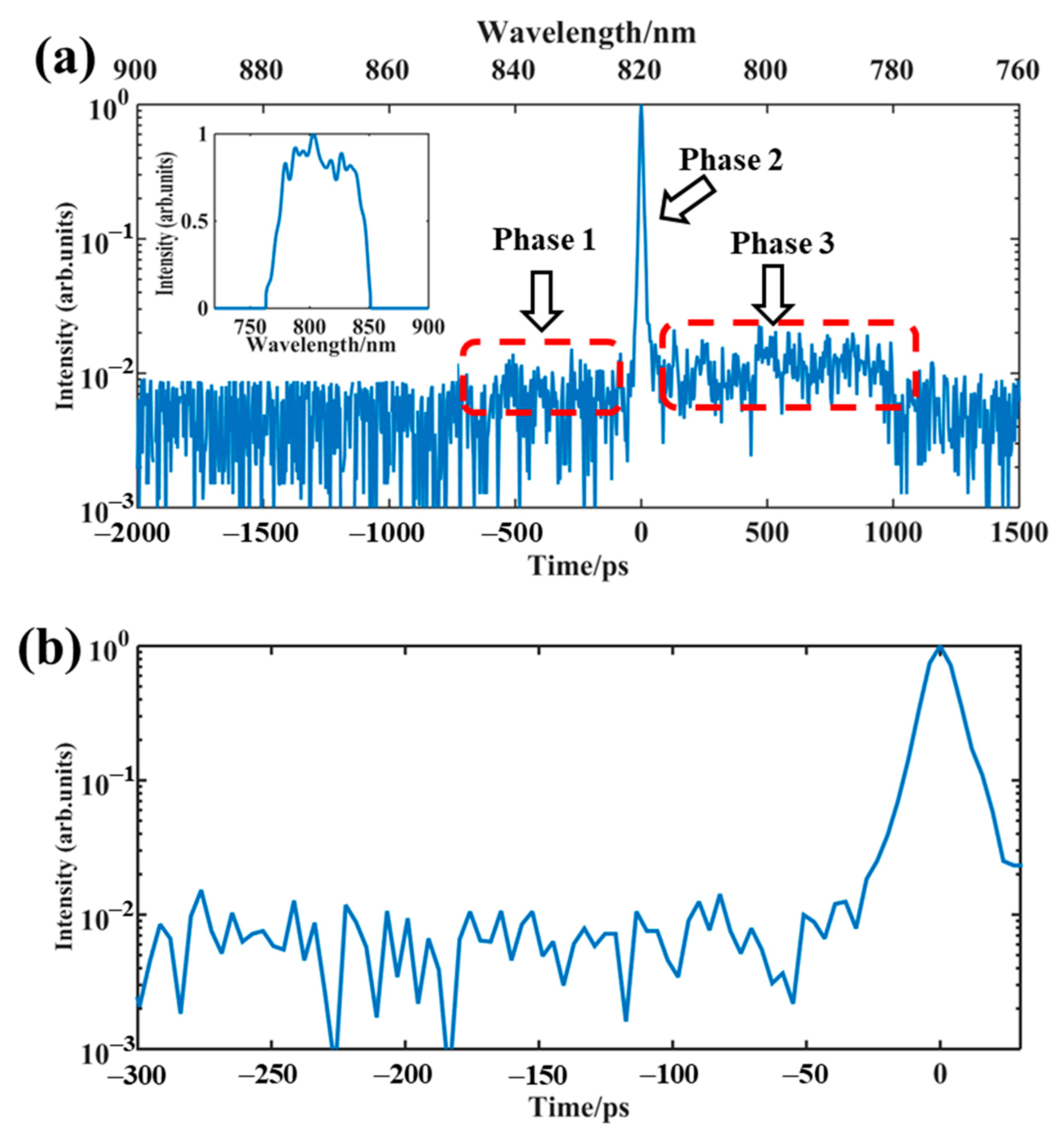
The single-shot temporal contrast enhancement measurement results of a PM are shown in
Figure 3. The original spectrum
obtained before is shown in the inset of
Figure 3a. The wavelength range is 750–850 nm, and the long wavelength corresponds to the rising edge. According to the chirp rate of 25 ps/nm, the effective temporal measuring range is 2.5 ns, and the corresponding measurement resolution is about 3.925 ps with the central wavelength. Using the Equation (1), the obtained recorded spectrum
is converted into the temporal profile
, as shown in
Figure 3a. The corresponding wavelength coordinates and the time coordinates are shown at the top and the bottom, respectively. The three spectra in
Figure 3a are specifically marked, corresponding to the three phases mentioned above in
Figure 1. Obviously, there is a particularly high peak in the spectrum, which is caused by the ultra-high reflectivity of the PM in phase 2, and the spectrum beyond phase 2 shows the low intensity. The rising edge of the spectrum corresponds to phase 1, which means the PM has not yet formed. The falling edge corresponds to phase 3, which means the PM is finished.
Besides, the intensity of the falling edge in phase 3 is slightly stronger than that of the rising edge. Excluding the possibility of stray light, we speculate that this appearance may be caused by the optical damage of the PM, as more scattered light enters the spectrometer through the damaged surface.
For more details of the enhancement, we chose the partial temporal profile range from −300 ps to +30 ps, as shown in
Figure 3b. As analyzed above, the contrast of the temporal reflectivity profile represents the temporal contrast enhancement of the PM. Thus,
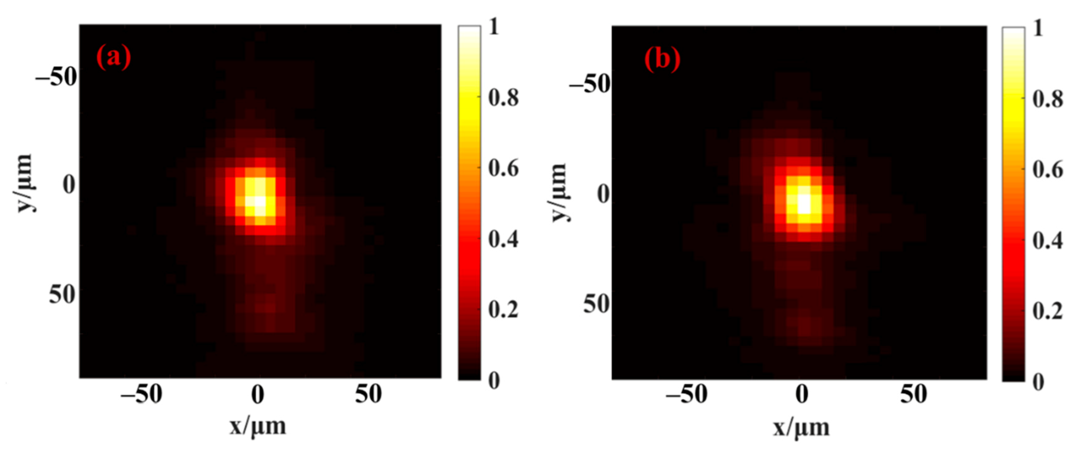
Figure 3b shows a temporal contrast enhancement of about two orders of magnitude for the delay time from 30 to 300 ps before the main pulse arrives. According to the fact that the temporal contrast enhancement of the PM is the ratio of efficiency (75%) to cold reflectivity (5‰), the theoretical value is about 150 times, which is in good agreement with the measurement results, and verifies the validity of the method. Moreover, several groups of test experiments were carried out alternately with and without the SOCP to determine the influence of the SOCP on PM performance. We recorded the efficiency and far-field patterns of output the igniting laser with and without the SOCP. By calculation, the average PM efficiency without the SOCP, and that of with the SOCP, are both maintained at a level about 75%. The far-field patterns results without the SOCP and with the SOCP are shown in
Figure 4a,b. Although the pixel numbers of the far-field patterns were limited by the spot size and pixel size, it is enough to judge whether the PM is degraded compared with the possible serious degradation phenomenon of the PM [
29]. Obviously, the two figures are highly similar in the spatial profile and surrounding micro speckles, indicating that the SOCP measurement does not affect PM performance. It is easy to understand that the PM is not affected as long as the intensity of the SOCP is not enough to interact with the target of the PM in advance. All of the key parameters of the PM, including the spectrum, far-field pattern, and efficiency, were obtained experimentally in a single-shot measurement. Combining the SOCP with calorimeters and CCD cameras for single-shot measurement has good potential for the online experimental monitoring of PM performance.
Except for the single-shot measurement of temporal contrast enhancement by the PM, SOCP has other characteristics in the PM measurement. Firstly, this method avoids the demand for sampling the main pulse after the PM, which is very helpful for reducing the energy loss and monitoring the characteristics of the PM in online high-power experiments. Secondly, this is a relative measurement method, and the required dynamic measuring range is dependent on the pulse-cleaning ability of the PM. For a single PM, the dynamic range of 102–103 is enough for the SOCP, while that of the traditional temporal contrast measurement method needs to reach 9 orders of magnitude. At present, the temporal contrast of high-power ultrashort pulses increases with the traction of physical demand, putting forward higher requirements and challenges for the dynamic measurement range of the temporal contrast of ultrashort petawatt and even exawatt lasers in the future. It should be mentioned that SOCP has potential use in the single-shot enhancement measurement of a double plasma mirror (DPM) system. DPM can achieve 104 enhancement, which is beyond the measurement ability of traditional methods. Moreover, it challenges the dynamic range of the spectrometer. After further improvement of the dynamic range, the SOCP is expected to be used for the single-shot measurement of DPM. Thirdly, the temporal measuring range is tunable by altering the chirp rate of SOCP, which is opposite to the temporal measurement resolution. The chirp rate of the SOCP should vary according to the different diagnostic purposes of the PM. In order to measure the temporal contrast enhancement of the PM, a hundred picosecond or nanosecond time scale is appropriate in the experiment. If aiming to determine the triggering time of the PM, the chirp rate should be altered. A higher resolution is needed to realize a more precise measurement on the temporal profile for revealing more information about the PM in the sub-picosecond scale. For example, if the chirp rate is 0.1 ps/nm, the duration of the SOCP is 100 ps, and the temporal resolution can reach 15.7 fs, which can provide more details about the generation process of the sub-picosecond-response PM. Moreover, the measurement capability of SOCP also significantly depends on the performance of the spectrometer. A high spectral resolution can enhance the measurement resolution, and a low noise spectrometer can improve the dynamic range and measurement accuracy of the SOCP.
4. Conclusions
In conclusion, we demonstrated the single-shot temporal contrast enhancement measurement of a plasma mirror by a spatiotemporally-overlapped chirped pulse of 2.5 ns duration. It relies on a single-shot reflective spectrum measurement of the chirped pulse after the plasma mirror is induced by the igniting laser. Compared with the common delay-scan third-order cross-correlator, this single-shot method is direct and convenient, as it can avoid the demand for multiple accurate measurement on temporal contrast and sampling of the igniting pulse, and the temporal resolution can be controlled by adjusting the chirp of SOCP. Experiments were performed on a test platform in the frontend of an SG-II 5PW laser system. Using the method, the temporal contrast enhancement 102 by a single plasma mirror was successfully measured, and was consistent with the theoretical value of 150. The effective temporal measuring range and measurement resolution are 2.5 ns and 3.925 ps, respectively. Moreover, we also monitored the efficiency and the far-field pattern of the igniting pulse to determine the influence on PM performance by the SOCP. The average PM efficiency maintained at about the 75% level, the equivalent to the original efficiency, and the far-field pattern showed no significant degradation, proving that an SOCP is suitable for the temporal contrast enhancement measurement of a plasma mirror. Finally, we hope that this work will contribute to the practical application of the temporal contrast enhancement measurement of plasma mirrors.


 ,
, 