Abstract
For the assumed bale volume, its dimensions (diameter, height), minimizing the consumption of the plastic film used for bale wrapping with the combined 3D method, depend on film and wrapping parameters. Incorrect selection of these parameters may result in an optimal bale diameter, which differs significantly from its height, while in agricultural practice bales with diameters equal or almost equal to the height dominate. The aim of the study is to formulate and solve the problem of selecting such dimensions of the bale with a given volume that the film consumption is minimal and, simultaneously, the bale diameter is equal or almost equal to its height. Necessary and sufficient conditions for such equilibria of the optimal bale dimensions are derived in the form of algebraic equations and inequalities. Four problems of the optimal bale dimension design guaranteeing assumed equilibrium of diameter and height are formulated and solved; both free and fixed bale volume are considered. Solutions of these problems are reduced to solving the sets of simple algebraic equations and inequalities with respect to two variables: integer number of film layers and continuous overlap ratio in bottom layers. Algorithms were formulated and examples regarding large bales demonstrate that they can handle the optimal dimensions’ equilibria problems.
1. Introduction
Currently, the demand to limit consumption of the film used to wrap bales of agriculture materials has been receiving increasing attention to reduce both costs and damage to the environment caused by plastic waste [1,2,3,4]. For this purpose, both experimental studies comparing film usage for different wrapping conditions and methods [5,6,7,8,9] and model-based analytical approaches useful for estimation of the film usage [10,11,12,13,14] and its minimization [15,16,17,18] were used. In the last few years it has been shown that by appropriate optimal selection of the film width [15,16], overlaps between adjacent film strips [17], and film width and overlaps, together, [18] it is possible to reduce film consumption by up to 20%. The model-based optimization research concerned mainly conventional [15,17,18] and IntelliWrap [16] wrapping methods. The monograph [19] comprehends the issues of modelling of the film consumption for wrapping round bales and related optimization problems solved in the last few years.
Also, an appropriate choice of bale size dimensions (diameter, height) may guarantee decreasing film consumption [11,19]. In [11], where the dependence of the film consumption on the bale diameter for the conventional wrapping technique was investigated, the analytical analysis showed that the larger the bale diameter is, the lower is the film consumption per unit of bale volume, which led to the conclusion that the use of the bale with the largest permissible diameter ensures the smallest film consumption. These studies were based on a rough model which describes film usage as a continuous function of bale dimensions, film width and a number of wrapped film strips; however, the model did not take into account mechanical properties of the stretch film and the direct relation between the number of wrapped film strips and bale and film parameters.
The concept of optimal (from the point of view of film consumption) selection of bale dimensions for the assumed bale volume was first introduced in [15] for the conventional wrapping method. A more accurate model was used that describes the consumption of the film as a function of the bale and film dimensions, mechanical parameters of the film (Poisson ratio, unit deformation), overlap ratio and the number of bale rotations [12]. The film consumption per unit of the bale volume is used as a measure of film usage. Since it is very difficult to find the optimal bale dimensions minimizing the original exact film usage index due to the discontinuity of this index, near-optimal parameters, being as important as optimal parameters for engineering applications, are sought. It was shown in [15] that in the case of using the conventional wrapping method, the optimal bale height is twice its optimal diameter. This optimality rule, which holds also for the IntelliWrap method [19], has only a theoretical character and is a consequence, among others, of multiple overlapping segments on the bale cylinder top and bottom, where there are 2–16 times more film layers than on the bale’s lateral surface [10,19]. However, in the case of the combined 3D wrapping method [6,14], the optimal bale dimensions turn out to be useful and applicable from the engineering practice point of view.
In the 3D wrapping method, which offers the potential to minimize film usage [6,14,20] as well as to enhance the quality of silage [6], biaxial rotation of the film applicators results in two types of film layers wrapped perpendicularly: the bottom layers are wrapped around the bale’s lateral surface and the upper layers are wrapped along the bale’s longitudinal axis. For a detailed description of the wrapping process, see [6] and the producer’s documentations [21,22,23]. The problem of the choice of the best bale dimensions to guarantee the minimal film consumption was solved in [20], where the optimality conditions were established in the form of algebraic cubic equations, which can easily be solved using both analytical and numerical methods. Analytical and numerical studies [19,20] have shown that the relation between the optimal diameter and height is not evident. The optimal diameter can be larger than the bale height [19] (Figure 6.5b), [20] (Figure 11c) or can be smaller than the bale height [19] (Figure 6.5d), [20] (Figure 11a), depending on the bale volume as well as film and wrapping parameters. But the optimal bale diameter can also be equal to its height [19] (Figure 6.5a,c), [20] (Figure 11b). The last case corresponds to typical large bales of 1.2 m diameter and height [10,24,25]. However, in agricultural practice typical bales are 1.2 to 1.3 m diameter and height [6,10,19], where diameter is equal [26,27,28,29,30] or almost equal [9,31,32], but not much bigger, than bale height. Other dimensions of large round bales, for example 1.2 m × 1.6 m Ø [33], or 1.2 m × 1.5 m Ø [34] or 1.5 m Ø [35], are used less frequently. Although round bales of the height greater than the diameter are also being investigated, for example 1.2 m × 0.9 m Ø [36], they are much less common in agriculture practice [37]. Standard 3D bale wrappers are designed to wrap cylindrical bales up to 1.6 m in diameter and up to 1.2 m in height [22], or up to 1.5 m diameter and 1.2 m height [21,23].
Therefore, the question becomes how to choose such film and wrapping process parameters for a round bale with a given volume wrapped using the 3D method so that the bale diameter minimizing film consumption is equal to or almost equal to its height. The aim of the paper is to solve the problem of the selection of the film and wrapping parameters (overlaps, numbers of bottom and upper film layers, etc.) that for a given bale volume, i.e., a given bale weight, its diameter and height are equal or near-equal and, at the same time, they minimize the film consumption. It is, in essence, the inverse problem in which the film and wrapping parameters are determined that the equilibria of optimal dimensions are guaranteed, while in the direct problem considered in [20] the optimal dimensions for a given parameters are sought. The thesis is that for any given bale volume and number of global film layers there exist film and wrapping parameters for which the optimal bale dimensions are equal or near-equal, with the pre-assumed proportions diameter/height. To prove the above, the necessary and sufficient conditions of equilibrium and near-equilibrium of the optimal bale dimensions were derived in the form of algebraic equations. The equilibrium conditions are dichotomous, as some depend on the given bale volume and others apply to any bale volume. Then, the problems of selecting such bale wrapping parameters for which the optimal bale dimensions are equal or near-equal were formulated and solved, separately, for a given and an arbitrary bale volume. Suitable design algorithms were proposed and numerically verified for large bales.
2. Materials and Methods
In this section, the notions of equal and near-equal optimal dimensions of a round bale are introduced and the related necessary and sufficient conditions are derived. The research methodology is also described.
2.1. Equal and Near-Equal Optimal Bale Dimensions
A complete mathematical model describing stretch film consumption for wrapping a bale with bottom and upper film layers using the combined 3D technique was derived in [14]; the main formula describing film usage is recalled in Appendix A with the corresponding assumptions. Symmetry of the bale is assumed. Mechanical properties of the plastic film are described by the Poisson’s ratio and unit deformation ; thickness of the film is ignored, e.g., polyethylene film is 25 μm thick [38]. The main symbols are summarized in Nomenclature, Appendix C.
The problem of the choice of bale dimensions (diameter, height) minimizing the consumption of the film used to wrap a cylindrical bale by 3D method has been stated and solved for the first time in [20], where the necessary and sufficient condition of the existence of the unique optimal bale diameter of the bale of pre-assumed volume was derived in the form of cubic equation with zero linear term coefficient [20]:
where is the width of stretched film described by Equation (A1), denotes the overlap of the extreme film strips in bottom film layers at the bases of the bale, and are the overlap ratios determining the width of the contact between adjacent film strips in bottom and upper film layers; function is defined by Equation (A3). The coefficients in the first and second terms and the free term of Equation (1) depend on the pre-assumed bale volume as well as all the film and wrapping parameters. Based on the optimality condition, Equation (1), analytical and numerical analysis of the influence of film width, pre-assumed bale volume and numbers of bottom and upper film layers on optimal bale dimensions and optimal film consumption were carried out in [20], where many detailed conclusions regarding the impact of these parameters were formulated. Additionally, the influence of the bottom layers overlaps was studied in [19].
Equation (1) has one real positive root [20]. The corresponding optimal bale height is [20]
For given the optimal and depend on film and wrapping parameters, they are linearly dependent and the difference between them is described by
From a quick inspection of Equation (3) it can be seen that the relation between the optimal diameter and height is not evident. The conducted research [19,20] has shown that the relations and , as well as are possible, depending on the values of the film and wrapping parameters and volume ; compare [20] (Figure 11), where the proportions diameter/height are depicted for large bales. Only the relation , desirable from the point of view of baling systems engineering, will be considered. The proportion diameter/height do not exceed 1.25 [22] (RW 1819, 150/120), or 1.2 [21] (BW 1850, 150/125), or [23] (WM 1851, 150/125); however, predominantly, it is of 1.05 order [21,22,23].
The goal of this paper is to study the selection of equal and nearly-equal optimal bale dimensions, therefore, the respective precise definitions are given.
Definition 1.
(equal optimal dimensions). Bale diameterand heightof bale with a volumeare called equal optimal dimensions, ifaccomplishes Equation (1) and , given by Equation (2), is equal to, i.e.,.
Definition 2.
(near-equal optimal dimensions). Bale diameterand heightof bale with a volumeare called near-equal optimal dimensions, ifaccomplishes Equation (1),is given by Equation (2), and
where a sufficiently small. Thenandare called nearly-equal with order.
2.2. Methodology
In this paper, a model-based analytical approach was applied, which addressed the goals (derivation of the conditions for equal and near-equal optimal bale dimensions and solving the problems of wrapping parameter design guaranteeing such equilibria) by using mathematical tools. The solutions of the optimality conditions for the bale diameter were obtained by applying numerical tools.
Firstly, the necessary and sufficient conditions under which for the given bale volume the optimal bale diameter is near-equal to its optimal height with order were derived using the optimality conditions expressed by Equations (1) and (2); Proposition 1 abstracts these results (Section 2.3.1). The conditions for optimal bale dimensions equilibria are given by algebraic equations. One of them uniquely relates bale volume to order and film and wrapping parameters, i.e., this condition is satisfied for a given volume. The complementary condition determined by two simple equations relating only to and film and wrapping parameter applies regardless of the bale volume. Based on these conditions, using differential calculus, the relationships between the volume of the bale with near-equal optimal dimensions and the order , width of the film and overlaps were analyzed (Section 2.3.2). Next, laying the conditions for exact equilibrium of the optimal bale dimensions was obtained directly from the conditions of their near-equilibrium (Section 2.3.3).
Knowing the conditions of equilibrium and near-equilibrium of optimal bale dimensions, the tasks of designing the wrapping process in such a way that these conditions would be satisfied were formulated and solved. Due to the dichotomous nature of the equilibrium conditions, design tasks for a given bale volume and those in which the bale volume is arbitrary were considered separately; these are covered in Section 3.1 and Section 3.2, respectively. Consequently, four design problems were solved; however, the solutions for equal optimal bale dimensions resulted directly from those for near-equilibrium by substituting (Section 3.3 and Section 3.4). It was assumed that the film parameters (width, mechanical parameters , ) are known, i.e., a practically available plastic film can be used, e.g., a commercial PE film used traditionally due to its mechanical properties and low costs [26,27,39]. Also the global number of film layers wrapped on the bale’s lateral surface was taken as a given. Many studies have investigated the number of desired film layers for baled silage preservation, for example [7,29,40,41]. Mostly, four, six or eight layers of film are applied [6,24,35]; however, ten, twelve, and even sixteen film layers in which the silages are wrapped are also considered [7,22,23,29]. Therefore no specific assumptions were taken concerning the number of global film layers; the numerical studies were conducted for from four to sixteen. The standard overlaps 50%, 67% or 75% resulting in uniform film coverage [17] were assumed for upper film layers. Thus, the bottom layers overlaps , and film layers decomposition had to be selected. The upper and lower limits were taken for the overlaps, the selection of which should take into account the knowledge and experience of baling as well as the possibilities of the wrappers available. Consequently, the considered design problems consisted in solving a set of algebraic equations (resulting from the conditions of the equilibria of optimal bale dimensions) and inequalities (the constraints of variables) with respect to three decision variables. Two variables—the overlaps , —were continuous, while the third—the number of bottom film layers —was integer. These mixed (hybrid) sets of equations and inequalities were solved analytically, separately for fixed and free bale volume. The solutions are abstracted by Propositions 4–7. For volume-free problems the solution is given by two inequalities directly related to the integer and simple rules for computing the overlaps , . In the case of fixed bale volume the solution was derived in the form of two inequalities related to the overlap ratio , which must be verified for every considered and unique algebraic rule for the determining of the overlap . If equal optimal bale dimensions are sought then these inequalities and formulas take particularly simple forms which are obtained by substituting . Computational algorithms were developed which enable designation of the sought wrapping parameters in a few steps. The examples illustrated how to use them (Excel is enough) as well as the effectiveness for optimal bale dimensions selection for a standard large bale.
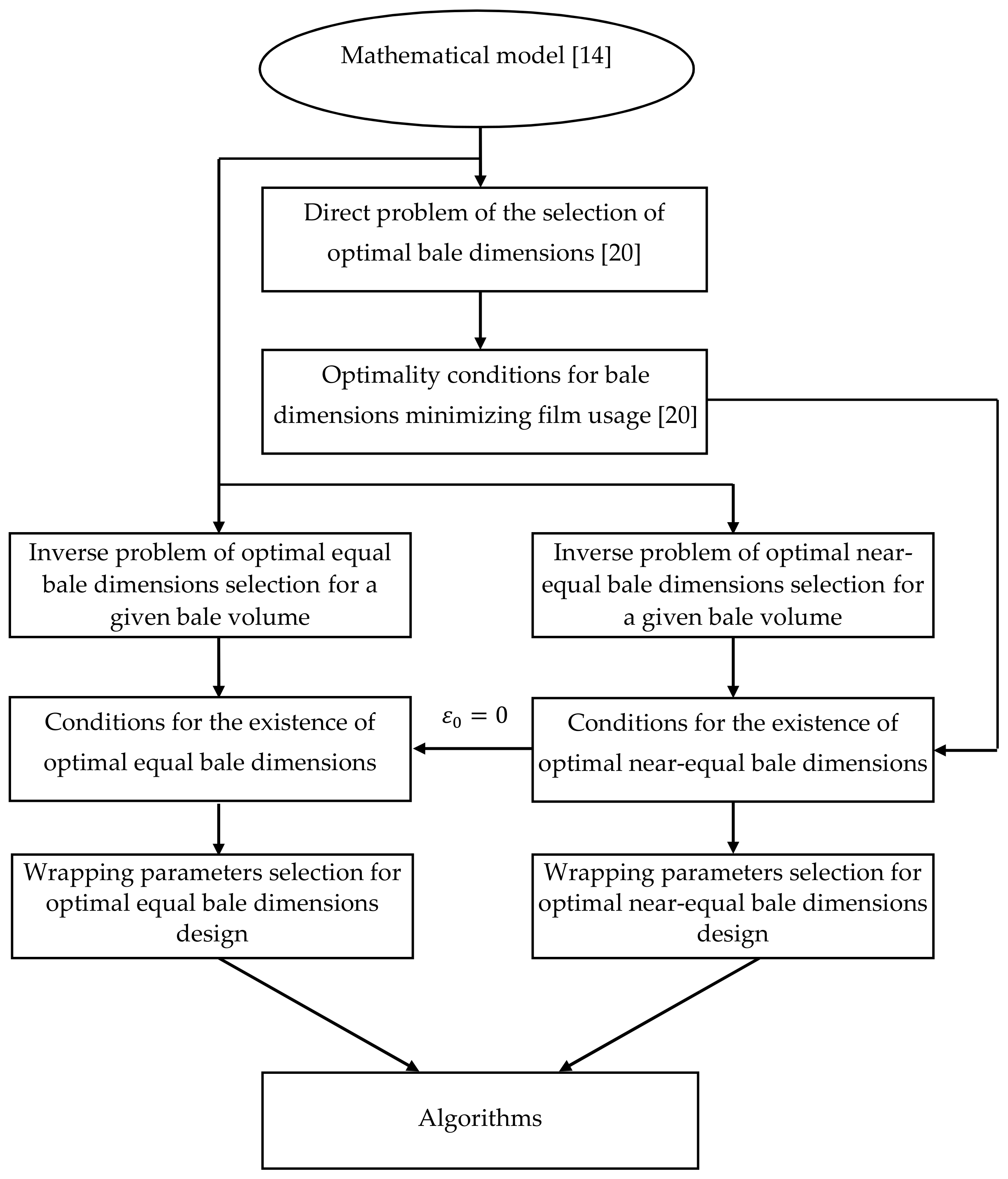
In sum, in the multistage process several problems of optimal equal and near-equal bale dimensions design for cylindrical bales of a given volume were formulated and solved. The research framework is graphically shown in Figure 1, which also illustrates the relations between these problems.

Figure 1.
Schematic framework for the tasks of designing optimal equal and near-equal bale dimensions.
2.3. Necessary and Sufficient Conditions of Bale Dimensions Equilibrium and Near-Equilibrium
2.3.1. Near-Equal Optimal Dimensions
By Definition 2, the optimal bale dimensions are such that Equation (4) holds and the optimality condition expressed by Equation (1) is satisfied. For a given bale volume Equations (2) and (4) yield
and
The necessary and sufficient conditions of near-equal optimal dimensions are given by the following proposition, which is proved in Appendix B.
Proposition 1.
For given: bale volume, widthof the film and its mechanical parameters,, numbers of film layers,and the overlaps,,, such that the applicability condition expressed by Equation (A4) holds, the optimal bale diameteris near-equal to its optimal heightwith orderin the sense of Definition 2 if and only if one (and only one) of the conditions is satisfied:
- (i)
- orderand the bale, film, and wrapping parameters are related by the equation
- (ii)
- the equationsandare satisfied, simultaneously. The optimal bale diameterand heightare described by Equations (5) and (6), respectively; in case (i) for a given bale volume, in case (ii) for an arbitrary volume.
The necessary and sufficient conditions for near-equal optimal bale dimensions, case (ii), are independent of ; they are volume–free. However, those from case (i) hold for given , i.e., they are volume-fixed.
Note, that the inequality
must hold to satisfy Equation (7); however, the expression may be positive or negative, depending on the sign of the denominator. The necessary condition expressed by Equation (10) is independent on , while Equation (7) depends on the particular value of bale volume . Both conditions depend on .
2.3.2. Bale Volume of Near-Equilibrium
From Equation (7), provided that inequality from Equation (10) is satisfied, we have
whence
Thus, for given film and wrapping parameters, bale volume resulting in near-equal optimal dimensions is monotonically increasing function of whenever
and decreases with , if . If inequality from Equation (12) holds, then the volume decreases if the overlap grows, while in the opposite case the influence of is not so evident and depends on the sign of the expression in the square brackets of the numerator in the last fraction of the right hand side of the following equation
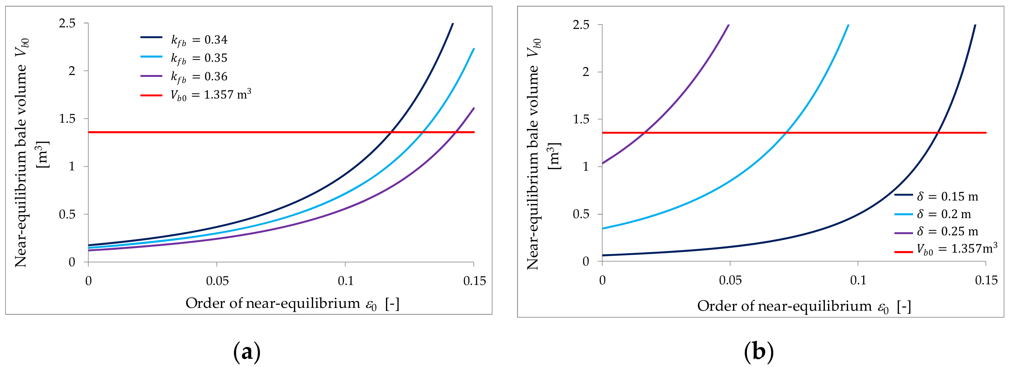
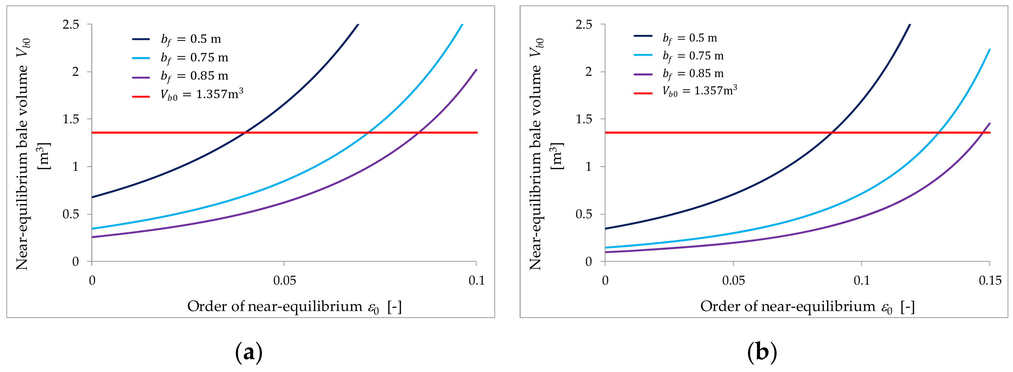
If condition from Equation (12) holds, then given by Equation (11) grows with the increase of the overlap . In the opposite case the larger is, the smaller is the volume resulting in near-equal optimal dimensions. From the analysis of Equation (11) it also follows that the greater film width is, the smaller is , provided that inequality from Equation (12) holds. The influence of the bottom layers overlaps and is illustrated in Figure 2a,b, where near-equilibrium volume is depicted as a function of for plastic film (e.g., polyethylene, PE) characterized by Poisson’s ratio [38] and unit deformation [7,12,14] of popular width [21,22,23,29,42]. Four bottom and upper film layers and overlap ratio are assumed. Figure 3a,b illustrate the effect of the film width for commonly used overlap [21,22,23] and two overlap ratios ; other parameters remain unchanged. The volume corresponding to a standard large bale of diameter and height [24,25] is also marked on these pictures. Finally, note that for standard overlap [6,14,20,21,22,23], PE film and since , the condition from Equation (12) holds, in particular, if the film width . For this requirement is reduced to . For exemplary and inequality from Equation (12) is satisfied for ; if this requirement is sharpened to .
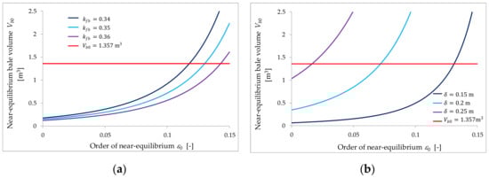
Figure 2.
The volume , Equation (11), yielding the near-equal optimal bale dimensions as a function of the order of near-equilibrium for bottom and upper film layers, film width and wrapping parameters: (a) overlaps and , (b) and .
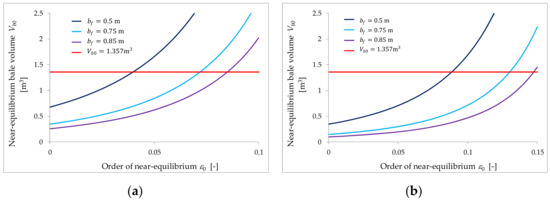
Figure 3.
The volume , Equation (11), yielding the near-equal optimal bale dimensions as a function of the order of near-equilibrium for bottom and upper film layers, overlap and parameters: (a) overlap ratio and film widths , (b) overlap ratio and film widths .
Since in practically used wrapping systems the condition expressed by Equation (12) is usually satisfied and the near-equilibrium bale volume increases with the order , a question arises about the conditions to be met by the film and wrapping parameters to guarantee for any the existence of a bale volume such that the optimal dimensions , are near-equal with order . The following result, derived in Appendix B based on Proposition 1, answers this question. The notation , , and is introduced, locally, for near-equal bale parameters to emphasize the relationship between and , , and .
Proposition 2.
For given film parameters ,, numbers of film layers,and the overlaps,,, such that the applicability condition expressed by Equation (A4) holds, for any, where a sufficiently small, there exists bale volumesuch that the optimal bale diameteris near-equal to its optimal heightwith ordernot greater than,i.e.,
if and only if
and one of the following conditions is satisfied:
- (a)
- inequality from Equation (12) holds,
- (b)
- two inequalitieshold, simultaneously. Then, for anyand volumeEquation (7) holds for. The optimal bale dimensions,are expressed by equations:In case (a),and,are monotonically increasing for. In case (b),and,are monotonically decreasing for. If inequalities from Equations (13) and (14) hold, but inequality expressed by Equation (15) not, then there exists positivesuch thatandFor anybale volumesatisfying Equation (7) and optimal bale dimensions,are near-equal in the sense of the inequalitiesBothand,are monotonically decreasing for.
Inequality expressed by Equation (12) holds for narrow films, while inequality form Equation (14) is satisfied for wider films.
2.3.3. Equal Optimal Dimensions
In this case the optimal bale diameter is equal to bale height, i.e., by Equation (2)
and the optimality condition expressed by Equation (1) is satisfied, simultaneously. The necessary and sufficient conditions for the equilibrium are given by the following proposition, which results directly from Proposition 1 for .
Proposition 3.
For given: bale volume, width of the filmand its mechanical parameters,, numbers of film layers,and the overlaps,,, such that the applicability condition expressed by Equation (A4) holds, the optimal bale diameteris equal to its optimal heightif and only if one (and only one) of the conditions is satisfied:
- (i)
- the bale, film and wrapping parameters are related by the equation
- (ii)
- the equationand Equation (9) are satisfied, simultaneously. The optimal bale dimensions are given directly by Equation (19) for fixed volumein case (i) or for arbitrary volume in case (ii).
Note, that in case (i) the necessary condition for bale dimensions equilibrium expressed by Equation (10) takes the form
3. Results and Discussion
In this section four problems of the selection of optimal bale dimensions being equal and near-equal are formulated, solved and illustrated by related examples.
It is known [17] that any overlap ratio of the form of irreducible fraction in which dividend is the divisor minus one, i.e.,
where , denotes the set of positive integer numbers, results in the uniform film distribution on the bale’s whole lateral surface and guarantee the same minimal film usage. An important special case for even is , which means 50% overlap between the successive film strips [6,17,24,43]. For function and since , the applicability condition expressed by Equation (A4) takes the form
From the practical perspective, only four or five smallest such overlap ratios are useful [6,17,22,24,43,44], i.e., are worth considering.
Bearing in mind the dichotomous nature of the equilibrium conditions specified by Propositions 1 and 3, the problems of volume-free and volume-fixed near-equal and equal bale optimal dimensions design will be considered, separately.
3.1. Volume-Free Near-Equal Optimal Bale Dimensions Design
Let us consider the following problem of the optimal choice of bale dimensions.
Problem 1.
Given film parameters,,, upper layers overlap ratio, Equation (20), number of global film layers, and the order of near-equilibrium. Find film layers decompositionand the bottom layers overlaps
whereandare the smallest and largest admissible overlap, and
whereandare the smallest and largest admissible, such that the applicability condition, Equation (21), holds and for any bale volumethe optimal bale dimensions,are near-equal with given order.
In view of Proposition 1, case (ii), the solution to the above problem exists if and only if there exist integer and continuous parameters , satisfying Equations (8) and (9), inequalities expressed by Equations (22) and (23), and the applicability condition, Equation (21). This set of equations and inequalities is solved in the Appendix B, this solution is summarized in the next result.
Proposition 4.
If inequality
holds, then the solution to the Problem 1 exists if and only if there exists an integersuch that inequalities:
are satisfied together with the applicability condition, Equation (21). For anysolving Problem 1 the overlap radiois given by equation
while by Equation (9) the overlap. For the assumed bale volume optimal bale dimensionsandare given by Equations (5) and (6), respectively.
Problem 1 is a mixed decision problem with integer variable and continuous variables , . From Proposition 4 the following algorithm follows.
3.1.1. Algorithm 1
Assume the inequality expressed by Equation (24) is satisfied and film parameters , , , upper layers overlap ratio , Equation (20), number of global film layers , and the order of near-equilibrium are given. Take minimal , and maximal , values of the overlaps , based on the knowledge and experience of baling to guarantee an appropriate tightness of the wrappings.
- Determine the set of all integer defined by the inequalitiesfor which there exists satisfying applicability condition, Equation (21).
- If the set is empty, then the solution to Problem 1 does not exist—go to step 3. Otherwise, go to step 4.
- Change the lower , or upper , bounds of wrapping parameters, or the order , or the film width and repeat the computations starting from step 1.
- For any compute the overlap ratio according to Equation (27) and, next, the overlap .
- If a bale volume is assumed, then for any compute film usage obtained for optimal , , Equations (5) and (6), using Equation (A2) and choose that which yields the minimal film consumption.
Application of Proposition 4 and Algorithm 1 is illustrated by an example.
3.1.2. Example 1
Plastic film of the parameters , and is assumed. Even numbers of global film layers and “uniform” overlap ratios , Equation (20), are considered. Firstly, the following bounds for bottom layers overlaps are assumed: , , , . Three orders of near-equilibrium are considered. Inequality from Equation (24) is satisfied. Unfortunately, the set of integer solutions of the inequalities expressed by Equation (28) is empty for all considered. When the lower constraint of is changed into , then for each the set is composed of a few . They are listed in Table 1 together with respective overlaps and . Bale volume is assumed, film usage for the optimal bale dimensions is computed and given in the last column of Table 1; for all for which the set is nonempty, there is only one . Note, that for given film usage obtained for , and decomposition are the same for all considered. Thus, the smallest can be chosen. For example, for taking we obtain near-equal optimal dimensions and . The same regularity holds for wider film , for which the solutions to Problem 1 are given in Table 2.

Table 1.
The numbers of global and bottom film layers and bottom layers overlaps , for which Problem 1 of volume-free near-equal optimal bale dimensions design has solution for the assumed order of near-equilibrium and bale from Example 1; film width , the bounds for constraints from Equations (22) and (23): , , , , were considered. Film usage , Equation (A2), for the optimal bale dimensions for bale volume .
Table 2.
The numbers of global and bottom film layers and bottom layers overlaps , for which Problem 1 of volume-free near-equal optimal bale dimensions design has solution for given order of near-equilibrium and bale from Example 1; film width , the bounds for constraints from Equations (22) and (23): , , , , were considered. Film usage , Equation (A2), for the optimal bale dimensions for bale volume .
3.1.3. Effect of the Non-Equilibrium Order
Parameter influences the constraints expressed by Equations (25) and (26). If grows, then for given both the lower and upper bounds for expressed by Equations (25) and (26) increase provided that the inequality form Equation (24) holds; however, these changes are not significant (see Table 1).
3.1.4. Effect of the Film Width
Film width , or equivalently , influence the inequality from Equation (24); if grows, then this inequality is still satisfied. Also, the lower and upper bounds from inequalities expressed by Equation (26) grow with . Thus, the increase of the film width can extend the set of integer which solve Problem 1. If, for example, the width , then for the set of solutions to Problem 1 for is not empty; for integer and the bottom layers overlaps , solve this task. The solutions to Problem 1 for and are summarized in Table 2.
3.2. Volume-Fixed Near-Equal Optimal Bale Dimensions Design
Based on Proposition 1, case (i), the following problem of bale dimensions optimal design was formulated.
Problem 2.
Given: film parameters,,, upper layers overlap ratio, Equation (20), number of global film layers, bale volume, and order of near-equilibrium. Find film layers decompositionand the bottom layers overlaps,satisfying constraints expressed by Equations (22) and (23) such that the optimal bale dimensions,yielding bale volumeare near-equal with orderand results in the minimal film usage.
Based on Proposition 1 and the properties of film consumption index , Equation (A2), with non-continuous ceiling function the solution of the above problem is derived in Appendix B. The next proposition abstracts this solution.
Proposition 5.
The solution to Problem 2 exists if and only if there exists an integerandsuch that inequalities:
are satisfied together with the applicability condition, Equation (21), where
andis given by
For any suchandthe overlapis given by equation
the optimal bale dimensions are described by Equations (5) and (6) and film usage
where denotes ceiling function [45]. Integersolving Problem 2 is such that
It may be easily shown that if the following inequality
holds, then
and condition from Equation (30) can be neglected. In all the tested examples the above inequality has been satisfied, compare Table 3 below. The inequality from Equation (37), similar to the condition expressed by Equation (12), holds especially if the number of bottom film layers is such that
Table 3.
The numbers of global and bottom film layers, lower , Equation (32), and upper bounds defined in Equations (33) and (31), parameters , Equation (30), the non-empty sets of overlap ratios defined by the inequalities expressed by Equations (29) and (30) and the linear functions, Equation (34), describing overlap for determined to find the solution to Problem 2 of near-equal optimal bale dimensions design for fixed volume , bale from Example 2; orders of near-equilibrium , film width , bounds for the constraints from Equations (22) and (23): , , , , . Film usage , Equation (35), for and ; the optimal defined in Equation (36) is marked by bold.
The inequalities specified in the above proposition must be solved for two variables: integer and continuous . For any fixed the overlap given by Equation (34) increases linearly with growing .
3.2.1. Algorithm 2
Assume film parameters , , , overlap ratio , Equation (20), number of global film layers , the order of near-equilibrium , and bale volume are given. Take minimal , and maximal , values of the overlaps , to guarantee the appropriate tightness of the wrappings.
- Determine the set of all integer for which there exists satisfying applicability condition, Equation (21), and the set of overlap ratios defined by the inequalities expressed by Equations (29) and (30) is nonempty.
- If the set is empty, then the solution to Problem 2 does not exist—go to step 3. Otherwise, go to step 4.
- Change the lower , or upper , bounds of wrapping parameters, or the order , or the film width and go to step 1.
- Solve in the integer programming task expressed by Equation (36) for .
- For the best choose practically reasonable , compute the overlap according to Equation (34) and optimal , using Equations (5) and (6). The minimal film consumption is equal to computed in step 4.
3.2.2. Example 2
Film parameters and overlaps constraints from Example 1 are taken, again. Bale volume is assumed together with orders of near-equilibrium and . Integer , bottom and upper bounds, parameters and closed intervals of are given in Table 3. In all tested examples . The upper bound of the closed interval of defined by Equation (29) is determined by , or , or —there is no rule here. For any the formulas from Equation (34) for computing are presented in the penultimate column. In the last column film usage , Equation (35), is given. For most the closed intervals are wide enough to select a practically convenient overlap ratio . In some cases this interval is very narrow, e.g., for , , we have ; however, is acceptable from the engineering point of view. For and set is composed of only one number of bottom film layers and this solves Problem 2. For there are at least two for which the set is nonempty, the optimal film usage defined in Equation (36) is marked by bold in Table 3. For , according to Equations (5) and (6), the optimal bale dimensions , , for we have , . If is assumed, then for the overlaps and can be applied. For Problem 2 is solved for the same overlaps for yielding minimal film usage. Similarly, for and . For solution to Problem 2 is composed by and, for example, and . For we have: and and . Similarly, based on the data from Table 3, the solutions to Problem 2 can be found for the greater order .
3.3. Volume-Free Optimal Equal Bale Dimensions Design
In this section the problem of volume-free design of equal optimal bale dimensions is considered being, in fact, a special case of Problem 1 for the order of near-equilibrium .
Problem 3.
Given: film parameters,,, overlap ratio, Equation (20), and number of global film layers. Find film layers decompositionand overlaps,satisfying constraints expressed by Equations (22) and (23) such that the applicability condition, Equation (21), hold and for any bale volumethe optimal dimensions,are equal.
The solution to the above problem is identical with that of Problem 1 for . Thus, the next result follows directly from Proposition 4 by lying in inequalities expressed by Equations (25) and (26) and in Equations (5), (6) and (27). Inequality from Equation (24), here , is identity.
Proposition 6.
The solution to Problem 3 exists if and only if there exists an integersuch that inequalities
are satisfied together with the applicability condition, Equation (21). For any suchthe bottom layers overlaps are uniquely determined by
For a given bale volume optimal bale dimensionsandare given by Equation (19).
Thus, to solve Problem 3 an integer fulfilling inequalities from Equation (39) must be found. The fractions dependent on in “max” and “min” functions, which define the lower and upper bounds in this inequalities, increase with the film width. However, the upper and lower bounds may be determined by other arguments of “max” or “min”, thus a larger does not necessarily imply a greater . Proposition 6 yielded the following algorithm.
3.3.1. Algorithm 3
Assume film parameters , , , overlap ratio , Equation (20), and the number of global film layers are given. Take minimal , and maximal , values of the overlaps , .
- Determine the set of all integer defined by the inequalities from Equation (39) for which there exists satisfying applicability condition, Equation (21).
- If the set is empty, then the solution to Problem 3 does not exist—go to step 3. Otherwise, go to step 4.
- Change the lower , or upper , bounds of wrapping parameters or the film width and go to step 1.
- For any compute the overlap ratio and, next, overlap according to Equation (40).
- For any and assumed bale volume compute film usage obtained for the optimal , , Equation (19), using Equation (A2) and choose that which yields the minimal film consumption.
3.3.2. Example 3
The same mechanical parameters of the film and wrapping parameters constraints as in the previous examples are assumed. Film widths and are considered. For , similarly as in Example 1, the set of integer solutions of inequalities expressed by Equation (39) is empty for all considered, while for the wider film for solution to Problem 3 exists. When the lower constraint expressed by Equation (22) is changed into , then for some Problem 3 has a solution. These solutions are listed in Table 4. For every , nonempty is a singleton (a unit set), thus step 5 of the selection of best film layers composition can be omitted here; however film usage is added in the last column.
Table 4.
The numbers of global and bottom film layers and bottom layers overlaps , for which Problem 3 of volume-free equal optimal bale dimensions design has a solution for bale from Example 3; film width , the bounds from Equations (22) and (23): , , , , . Film usage , Equation (A2) for the assumed bale volume .
3.4. Volume-Fixed Optimal Equal Bale Dimensions Design
Problem 4.
Given: film parameters,,, overlap ratio, Equation (20), number of global film layersand bale volume. Find film layers decompositionand overlaps,satisfying constraints from Equations (22) and (23) such that the optimal bale dimensions,resulting in the volumeare equal and film usage is minimal.
Lying in inequalities expressed by Equations (29) and (30) and in Equations (34) and (35) based on Proposition 5 the following solution results.
Proposition 7.
The solution to Problem 4 exists if and only if there existand an integersuch that inequalities
and inequality
are satisfied together with the applicability condition, Equation (21), where
andis defined by the next equation withintroduced in Equation (41)
For any suchandthe overlapis given by
the optimal bale dimensions are given by Equation (19) and film usage
Integersolving Problem 4 is defined by optimization task expressed by Equation (36).
Thus, the inequalities specified in the proposition must be solved for two variables: integer and continuous . Next optimization task, Equation (36), must be solved and the overlap can be computed.
Example 4
Film parameters and overlap ratio as in the previous examples are given. Film widths , even such that and bale volume are assumed. For any the sets of overlap ratios satisfying inequalities from Equations (41) and (42) are given in the fourth column of Table 5. As previously, for any from these closed intervals the linear formulas from Equation (45) for computing are given in the next column, in the last column film consumptions , Equation (46), are enclosed. For these for which there are more than one such that inequalities from Equations (41) and (42) are satisfied the minimal film usage, solving optimization task from Equation (36), is marked by bold. Note that in most cases film usage for is smaller from that for ; this confirms the analysis of the film width influence on the optimal film usage from [14,20]—the broader film width is applied, the smaller minimal film usage is achieved.
Table 5.
The numbers of global and bottom film layers, bottom layers overlaps , fulfilling inequalities from Equations (41) and (42), and respective film usage , Equation (46), for and bale from Example 4; film widths , the bounds from Equations (22) and (23): , , , , . Minimal film usage solving Problem 4 of volume-fixed design of equal optimal bale dimensions is marked by bold.
3.5. Optimal Film Usage
For the combined 3D wrapping technique, the analysis of the optimal film consumption reached for , was carried out in [19,20], where it was shown, in particular, that for the bottom film layers the optimal selection of bale diameter and height may result in a 3.37% to even 23.13% reduction in film usage depending on the number of global film layers and wrapping parameters, which means up to 23% film cost savings. Many conclusions regarding the impact of film width, pre-assumed bale volume and numbers of bottom and upper film layers on near-optimal bale dimensions and near-optimal film consumption were formulated [19,20].
4. Conclusions
It has been shown that for bale wrapping by a 3D combined method for given film parameters and given a global number of film layers it is possible, both for assumed and for an arbitrary bale volume, to select such wrapping parameters that guarantee the pre-assumed equilibria of optimal bale dimensions. Thus, the “compliance” is the answer to the question from the title.
The derived necessary and sufficient conditions for the balance of optimal bale dimensions allowed for the formulating of four practical problems of selecting the wrapping parameters, in particular the overlaps in the bottom film layers and decomposition of the global number of layers into bottom and upper layers. The mathematical form of the conditions of optimal bale dimensions equilibrium indicated the legitimacy of considering two separate design strategies, one for fixed and one for free bale volume. Design algorithms were derived. These algorithms only require a solution with respect to the number of film layers and overlap ratio of the bottom film layers of two or four simple algebraic inequalities. Then, on the basis of very simple formulas, the remaining wrapping parameters and the optimal bale diameter and height can be determined. Examples regarding standard large bales demonstrate that the algorithms can handle the optimal dimensions’ equilibria problems.
Optimal dimensions mean a reduction in film consumption by up to 23%. Simultaneously, equal and near-equal bale dimensions are essential from the agriculture engineering practice and bale wrapping technique point of view. The algorithms developed can be applied for design of wrapping processes using a 2D method for cylindrical bales of arbitrary agricultural materials, e.g., lignocellulosic agricultural residues [46,47], bearing in mind the minimisation of the film usage and the desired equilibrium between bale dimensions. Potential applications of the algorithms include the baling of waste, such as municipal solid waste [48,49], for example.
Funding
This research received no external funding.
Institutional Review Board Statement
Not applicable.
Informed Consent Statement
Not applicable.
Conflicts of Interest
The author declares no conflict of interest.
Appendix A
Appendix A1. Film Consumption
A mathematical model describing the consumption of the stretch film to wrap a cylindrical bale using combined 3D technique was derived in [14]. It was assumed that the subsequent film strips, which are wrapped in bottom layers on the bale’s lateral surface, overlap one another, creating the overlap , where is a dimensionless relative ratio determining the width of the contact between adjacent film strips and the film width after stretching is described by [12]:
where is the width of un-stretched film, and are the Poisson’s ratio and unit deformation of the film. The extreme film strips are overlapped at the bases of the bale for , as shown in [14] (Figure 3). It was assumed that , for which only one film layer results for one wrapping cycle. For the wrappings of upper layers it was assumed that the subsequent film strips are wrapped along the bale’s longitudinal axis with the overlap ratio [14] (Figure 2).
The global film consumption measured by the index defined as the ratio of the surface area of un-stretched film used to wrap the bale to bale volume, is described by the function [14]:
where denotes ceiling function [45], function [20]
is introduced for brevity of the notation; is the floor function [45]. The above formula indicates the dependence of the film usage on film parameters , , , bale diameter and height , the overlaps , and of the bottom and upper film layers, and the numbers of film layers , . Second summand of describe film used for upper layers wrappings provided that the following applicability condition [14]:
holds, where denotes the set of positive integer numbers. Global number of basic film layers wrapped on the bale’s lateral surface is .
Appendix A2. Film Consumption Minimization
As the non-continuity and non-differentiability of the original film usage index FC undermines our ability to directly analytically solve the problem of film usage minimization, special attention has been given to the simpler case of near-optimal bale dimensions design, this being as important as the optimal parameters for engineering applications. The problem of the selection of near-optimal bale dimensions has been constructed by minimizing continuous lower bound of the original film usage index FC, where the goal function of a non-linear optimization problem is convex and differentiable. The necessary and sufficient optimality condition for near-optimal bale diameter, called “optimal” in [20] and here, was established in the form of a standard cubic equation, Equation (1), which can easily be solved using both analytical and numerical methods. The results of the numerical experiments [19,20] demonstrated that for any four to sixteen even layers of the film there are such compositions of bottom and upper film layers that the relative near-optimality errors do not exceed 0.01% whenever the optimal bale dimensions are used.
Appendix B
Proof of Proposition 1.
The optimal bale diameter is near-equal to the optimal bale height with order if and only if Equations (1) and (5) are satisfied, simultaneously. For given by Equation (5) the optimality condition, Equation (1), takes the form
and is equivalent to the next equation
which can be rewritten as follows
To show the Proposition two cases must be considered separately:
- (i)
- the wrapping parameters and order are such that
- (ii)
- for the wrapping parameters and the following equality holds
Provided that inequality from Equation (A6) is satisfied, we have
whence Equation (7) follows. The optimal bale diameter and height are described by Equations (5) and (6) and for and Equations (1) and (5) are satisfied; case (i) is proved.
In case (ii), when Equation (A7) holds, Equation (A5) is satisfied if and only if, simultaneously,
Then, Equation (1) takes especially simple form
whence the optimal bale diameter
Simultaneously, from Equation (A7) it follows that
Thus Equations (A9) and (5) are identical and, by Equation (4), formula from Equation (6) follows for any , which completes the proof of case (ii) since Equations (A7) and (8) are equivalent. □
Proof of Proposition 2.
and, simultaneously, Equation (9) holds. In the second case any change of to results in a loss of equality in Equation (A10). Then the inequality expressed by Equation (13) holds, i.e., case (i) occurs, and since according to Equation (9) , we immediately conclude that Equation (7) is satisfied only for volume . Thus, if for Equation (A10) holds, the optimal bale dimensions cannot be near-equal for any .
By Proposition 1 the optimal bale dimensions are near-equal with order if:
- in case (i) inequality expressed by Equation (13) is satisfied,
- in case (ii)
Assume now, that for the inequality expressed by Equation (13) is satisfied. Let us consider bale volume uniquely given by Equation (7). Differentiating Equation (7) on both sides with respect to results in
whence, after algebraic manipulations, we obtain
Thus, monotonicity of the function depends on the sign of the expression . First, consider case (a) of the proposition assuming that inequality from Equation (12) holds. Then the denominator of the left hand side of Equation (7) is also positive, and if inequality given by Equation (13) holds for , then it holds also for any . Function is monotonically increasing for . For , by Equations (5), (6) and (A8), the optimal bale dimensions , can be equivalently expressed by Equations (16) and (17). Thus, , are also monotonically increasing for .
In case (b), when inequality expressed by Equation (14) is satisfied, function decreases with and, by Equation (7), inequality from Equation (13) takes the form
If, simultaneously, inequality expressed by Equation (15) holds, then for any there exists fulfilling Equation (7). Otherwise, there exists such that Equation (18) holds and only for Equation (7) is satisfied for some . In both cases, for or , by Equation (16) we have
Thus, in view of the inequality from Equation (14), optimal bale diameter decreases with increasing . The analysis of Equation (17) yields analogous property of . Proposition 2 is proved. □
Proof of Proposition 4.
For expressed by Equation (20) and Equation (8) takes the form
whence the bottom layers overlap ratio is uniquely determined by Equation (27). The overlaps and are related by Equation (9). Substituting , Equation (27), into constraints described by Equation (23) leads to inequalities
which can be rewritten in the equivalent form of constraints expressed with respect to integer by Equation (25).
Simultaneously, on the basis of Equations (9) and (27), the constraints expressed by Equation (22) are satisfied if and only if
which is equivalent to the inequalities expressed by Equation (26), provided that inequality described by Equation (24) is satisfied. Proposition 4 is derived. □
Proof of Proposition 5.
According to Proposition 1 the solution to Problem 2 exists if and only if there exist integer and overlaps , satisfying Equation (7), constraints from Equations (22) and (23) and the applicability condition, Equation (21), provided that the denominator of the left hand side of Equation (7) is non-zero, i.e., that inequality from Equation (13) holds, which for and can be rewritten as
The above condition can be expressed directly with respect to the overlap ratio as inequality described by Equation (30). By Equation (7), having in mind that and , the overlap is uniquely given by equation
whence direct formula from Equation (34) follows. Thus, the inequalities from Equation (22) take the form
and can be unravelled with respect to as follows
Simultaneously, for the overlap ratio inequalities from Equation (23) must be satisfied.
It has been proved above that there exist decomposition and the bottom layers overlaps , satisfying constraints expressed by Equations (22) and (23) such that the optimal , of the bale of volume are near-equal with order if and only if there exist an integer and continuous parameter such that inequalities expressed by Equations (A12) and (23), i.e., jointly
are satisfied together with the applicability condition, Equation (21), and inequality from Equation (30). For any such and the overlap is given by Equation (34). By Proposition 1 the optimal bale dimensions are given by Equations (5) and (6). Since by Equation (34), we have
having in mind that it can be proved that for the optimal , film usage index , Equation (A2), is described by
where only numerator of the fraction in the argument of the ceiling function in the first sum in curly brackets depends on and is non-decreasing left-continuous function of , piecewise constant in the intervals determined by its discontinuity points. If is discontinuity point being direct right neighbourhood of defined in Equation (A13), i.e., for the following equation holds
then for any
film usage , Equation (A14), being left-continuous in discontinuity points is identical. Thus, combining inequalities from Equations (A12), (23), and (A16) result in the inequalities from Equation (29). Direct formula expressed by Equation (33) follows from Equation (A15), while Equation (35) results directly from Equation (A14). Integer minimization task in Equation (36) makes it possible to find the best film layers decomposition. Proposition 5 is true. □
Appendix C
Appendix C1. Nomenclature
| width of un-stretched film, m | |
| width of stretched film, Equation (A1), m | |
| , | bale diameter and height, m |
| optimal bale diameter, solution of Equation (1), m | |
| optimal bale height given by Equation (2), m | |
| film consumption index, Equation (A2), m−1 | |
| , | overlap ratios applied to wrap bottom and upper film layers |
| , | the smallest and largest admissible , Equation (23) |
| lower bound of solving Problem 2, Equation (32) | |
| , | upper bounds of solving Problem 2, Equations (33) and (31) |
| lower bound of solving Problem 4, Equation (41) | |
| , | bounds of solving Problem 4, Equations (43) and (44) |
| set of overlap ratios defined for by Equations (29) and (30) | |
| integer number | |
| set of all positive integer numbers | |
| global number of basic film layers | |
| , | numbers of basic film layers in bottom and upper layers |
| optimal solving Problems 2 and 4 defined in Equation (36) | |
| set of for which Problem 1 has solution, defined in Equation (28) | |
| , | sets of for which Problems 2,3 have solution |
| Poisson’s ratio of the stretch film | |
| pre-assumed bale volume, m3 | |
| order of nearly-equal bale dimensions introduced in Equation (4) | |
| unit deformation of the stretch film | |
| function of the overlap ratio defined by Equation (A3) | |
| overlap of extreme film strips at base of bale, m | |
| , | the smallest and largest admissible overlap δ, Equation (22), m |
Appendix C2. Mathematical Terminology
| the smallest integer not less than , ceiling function | |
| the largest integer not greater than , floor function |
References
- Muise, I.; Adams, M.; Côté, R.; Price, G. Attitudes to the recovery and recycling of agricultural plastics waste: A case study of Nova Scotia, Canada. Resour. Conserv. Recycl. 2016, 109, 137–145. [Google Scholar] [CrossRef]
- Pazienza, P.; De Lucia, C. For a new plastics economy in agriculture: Policy reflections on the EU strategy from a local perspective. J. Clean. Prod. 2020, 253, 119844. [Google Scholar] [CrossRef]
- Rotz, C.A.; Stout, R.; Leytem, A.; Feyereisen, G.; Waldrip, H.; Thoma, G.; Holly, M.; Bjorneberg, D.; Baker, J.; Vadas, P.; et al. Environmental assessment of United States dairy farms. J. Clean. Prod. 2021, 315, 128153. [Google Scholar] [CrossRef]
- Tkaczyk, S.; Drozd, M.; Kędzierski, Ł.; Santarek, K. Study of the Stability of Palletized Cargo by Dynamic Test Method Performed on Laboratory Test Bench. Sensors 2021, 21, 5129. [Google Scholar] [CrossRef]
- Baldasano, J.; Gassó, S.; Pérez, C. Environmental performance review and cost analysis of MSW landfilling by baling-wrapping technology versus conventional system. Waste Manag. 2003, 23, 795–806. [Google Scholar] [CrossRef]
- Borreani, G.; Bisaglia, C.; Tabacco, E. Effects of a New-Concept Wrapping System on Alfalfa Round-Bale Silage. Trans. ASABE 2007, 50, 781–787. [Google Scholar] [CrossRef]
- Hong, S.; Kang, D.; Kim, D.; Lee, S. Analysis of bale surface pressure according to stretch film layer changes on round bale wrapping. J. Biosyst. Eng. 2017, 42, 136–146. [Google Scholar]
- Li, L.; Wang, D.; Yang, X. Study on round rice straw bale wrapping silage technology and facilities. Int. J. Agric. Biol. Eng. 2018, 11, 88–95. [Google Scholar] [CrossRef]
- Tabacco, E.; Bisaglia, C.; Revello-Chion, A.; Borreani, G. Assessing the Effect of Securing Bales with either Polyethylene Film or Netting on the Fermentation Profiles, Fungal Load, and Plastic Consumption in Baled Silage of Grass-Legume Mixtures. Appl. Eng. Agric. 2013, 29, 795–804. [Google Scholar]
- Ivanovs, S.; Gach, S.; Skonieczny, I.; Adamovičs, A. Impact of the parameters of round and square haylage bales on the consumption of the sealing film for individual and in-line wrapping. Agron. Res. 2013, 11, 53–60. [Google Scholar]
- Gach, S.; Piotrowska, E.; Skonieczny, I. Foil consumption in wrapping of the single green forage bales. Ann. Wars. Agric. Univ. Life Sci.-SGGW Agric. 2010, 56, 13–20. [Google Scholar]
- Stępniewski, A.; Nowak, J.; Stankiewicz, A. Analytical model of foil consumption for cylindrical bale wrapping. Econtechmod Int. Q. J. Econ. Technol. Model. Process. 2016, 5, 78–82. [Google Scholar]
- Stępniewski, A.; Nowak, J. The effect of additional foil wraps on the tightness of the packaging of bales. Econtechmod Int. Q. J. Econ. Technol. Model. Process. 2018, 7, 145–150. [Google Scholar]
- Stankiewicz, A. Model-Based Analysis of Stretch Film Consumption for Wrapping Cylindrical Baled Silage Using Combined 3D Method. Trans. ASABE 2019, 62, 803–820. [Google Scholar] [CrossRef]
- Stankiewicz, A.; Stępniewski, A.; Nowak, J. On the mathematical modelling and optimization of foil consumption for cylindrical bale wrapping. Econtechmod Int. Q. J. Econ. Technol. Model. Process. 2016, 5, 101–110. [Google Scholar]
- Stankiewicz, A. Minimizing the Consumption of Stretch Film for Wrapping Cylindrical Baled Silage Using the IntelliWrap Method. Trans. ASABE 2020, 63, 967–980. [Google Scholar] [CrossRef]
- Stankiewicz, A. On the uniform distribution and optimal consumption of stretch film used for wrapping cylindrical baled silage. Grass Forage Sci. 2019, 74, 584–595. [Google Scholar] [CrossRef]
- Stankiewicz, A. Optimal and Robustly Optimal Consumption of Stretch Film Used for Wrapping Cylindrical Baled Silage. Agriculture 2019, 9, 248. [Google Scholar] [CrossRef] [Green Version]
- Stankiewicz, A. Modelling and Optimisation of the Consumption of Stretch Film for Wrapping Baled Silages, 1st ed.; Polihymnia: Lublin, Poland, 2020. [Google Scholar]
- Stankiewicz, A. Optimization and Analysis of Plastic Film Consumption for Wrapping Round Baled Silage Using Combined 3D Method Considering Effects of Bale Dimensions. Trans. ASABE 2021, 64, 727–743. [Google Scholar] [CrossRef]
- Bale Wrappers. BW 1100-1104-1200-1400-1600-1604-1850. Brochure. Vicon. Available online: http://www.to-da.si/wp-content/uploads/2009/12/ovijalke.pdf (accessed on 26 June 2021).
- Baler-Wrapper Combinations. i-BIO+, FBP, VBP. Brochure. Saverne, France: Kuhn. Available online: https://docplayer.net/146964369-Baler-wrapper-combinations-i-bio-fbp-vbp-be-strong-be.html (accessed on 26 June 2021).
- WRAPMASTER.1121•1221•1431•1631•1851•1124•1634•4034. Brochure. Deutz-Fahr Evolving Agriculture. Available online: http://www.expansaolda.pt/conteudos/File/Catalogo/Deutz%20Fahr/deutz%20fahr%20WrapMaster%20GB.pdf (accessed on 26 June 2021).
- Bortolini, M.; Cascini, A.; Gamberi, M.; Mora, C. Environmental assessment of an innovative agricultural machinery. Int. J. Oper. Quant. Manag. 2014, 20, 243–258. [Google Scholar]
- Coblentz, W.; Akins, M.; Cavadini, J. Fermentation characteristics and nutritive value of baled grass silages made from meadow fescue, tall fescue, or an orchardgrass cultivar exhibiting a unique nonflowering growth response. J. Dairy Sci. 2020, 103, 3219–3233. [Google Scholar] [CrossRef]
- Borreani, G.; Tabacco, E. New Oxygen Barrier Stretch Film Enhances Quality of Alfalfa Wrapped Silage. Agron. J. 2008, 100, 942–948. [Google Scholar] [CrossRef]
- Borreani, G.; Tabacco, E. Use of New Plastic Stretch Films with Enhanced Oxygen Impermeability to Wrap Baled Alfalfa Silage. Trans. ASABE 2010, 53, 635–641. [Google Scholar] [CrossRef]
- McEniry, J.; Forristal, P.D.; O’Kiely, P. Gas composition of baled grass silage as influenced by the amount, stretch, colour and type of plastic stretch-film used to wrap the bales, and by the frequency of bale handling. Grass Forage Sci. 2011, 66, 277–289. [Google Scholar] [CrossRef]
- McEniry, J.; Forristal, P.D.; O’Kiely, P. Factors influencing the conservation characteristics of baled and precision-chop grass silages. Ir. J. Agric. Food Res. 2011, 50, 175–188. [Google Scholar]
- Sun, Y.; Cheng, Q.; Meng, F.; Buescher, W.; Maack, C.; Ross, F.; Lin, J. Image-based comparison between a γ-ray scanner and a dual-sensor penetrometer technique for visual assessment of bale density distribution. Comput. Electron. Agric. 2012, 82, 1–7. [Google Scholar] [CrossRef]
- Li, P.; Gou, W.; Zhang, Y.; Yang, F.; You, M.; Bai, S.; Shen, Y. Fluctuant storage temperature increased the heterogeneous distributions of pH and fermentation products in large round bale silage. Grassl. Sci. 2019, 65, 155–161. [Google Scholar] [CrossRef]
- Coblentz, W.; Coffey, K.; Chow, E. Storage characteristics, nutritive value, and fermentation characteristics of alfalfa packaged in large-round bales and wrapped in stretch film after extended time delays. J. Dairy Sci. 2016, 99, 3497–3511. [Google Scholar] [CrossRef] [PubMed]
- Martelli, R.; Bentini, M.; Monti, A. Harvest storage and handling of round and square bales of giant reed and switchgrass: An economic and technical evaluation. Biomass Bioenergy 2015, 83, 551–558. [Google Scholar] [CrossRef]
- Román, F.D.; Hensel, O. Numerical simulations and experimental measurements on the distribution of air and drying of round hay bales. Biosyst. Eng. 2014, 122, 1–15. [Google Scholar] [CrossRef]
- Schenck, J.; Müller, C.; Djurle, A.; Jensen, D.F.; O’Brien, M.; Johansen, A.; Rasmussen, P.H.; Spörndly, R. Occurrence of filamentous fungi and mycotoxins in wrapped forages in Sweden and Norway and their relation to chemical composition and management. Grass Forage Sci. 2019, 74, 613–625. [Google Scholar] [CrossRef]
- Arco-Pérez, A.; Ramos-Morales, E.; Yáñez-Ruiz, D.; Abecia, L.; Martin-Garcia, A.I. Nutritive evaluation and milk quality of including of tomato or olive by-products silages with sunflower oil in the diet of dairy goats. Anim. Feed. Sci. Technol. 2017, 232, 57–70. [Google Scholar] [CrossRef]
- Nowak, J.W.; Stępniewski, A.; Bulgakov, V. Machines for Wrapping of the Ensiled Forage with Film; University of Life Sciences Publishing House: Lublin, Poland, 2019. (In Polish) [Google Scholar]
- Zhang, S.L.; Li, J.C.M. Anisotropic elastic moduli and Poisson’s ratios of a poly(ethylene terephthalate) film. J. Polym. Sci. B Polym. Phys. 2004, 42, 260–266. [Google Scholar] [CrossRef]
- Borreani, G.; Tabacco, E. New concepts on baled silage. In Proceedings of the 2nd International Conference on Forages, Lavras, Brazil, 28–30 May 2018; Ávila, C.L.S., Casagrande, D.R., Lara, M.A.S., Bernardes, T.F., Eds.; SUPREMA Gráfica e Editora Ltda: Lavras, Brazil, 2018; pp. 49–73. [Google Scholar]
- Nonaka, K.; Nakuit, T.; Ohshita, T. The effects of the number of film wrapping layers and moisture content on the quality of round bales of low moisture timothy silage. Grassl. Sci. 1999, 45, 270–277. [Google Scholar]
- Coblentz, W.; Akins, M. Silage review: Recent advances and future technologies for baled silages. J. Dairy Sci. 2018, 101, 4075–4092. [Google Scholar] [CrossRef] [PubMed]
- Wang, J.; Bu, D.; Guo, W.; Song, Z.; Zhang, J. Effect of storing total mixed rations anaerobically in bales on feed quality. Anim. Feed. Sci. Technol. 2010, 161, 94–102. [Google Scholar] [CrossRef]
- Wilkinson, J.M.; Rinne, M. Highlights of progress in silage conservation and future perspectives. Grass Forage Sci. 2018, 73, 40–52. [Google Scholar] [CrossRef]
- Gaillard, F. L’ensilage en balles rondes sous film étirable. Fourrages 1990, 123, 289–304. [Google Scholar]
- Graham, R.L.; Knuth, D.E.; Patashnik, O.; Liu, S. Concrete Mathematics: A Foundation for Computer Science. Comput. Phys. 1989, 3, 106–107. [Google Scholar] [CrossRef]
- Geletukha, G.; Drahniev, S.; Zheliezna, T.; Zubenko, V.; Haidai, O. Technologies for energy production from lignocellulosic agricultural residues. In Innovative Renewable Waste Conversion Technologies; Springer Science and Business Media LLC: Cham, Switzerland, 2021; pp. 281–345. [Google Scholar]
- Tang, Z.; Zhang, B.; Liu, X.; Ren, H.; Li, X.; Li, Y. Structural model and bundling capacity of crawler picking and baling machine for straw wasted in field. Comput. Electron. Agric. 2020, 175, 105622. [Google Scholar] [CrossRef]
- Tumuluru, J.S.; Yancey, N.A.; Kane, J.J. Pilot-scale grinding and briquetting studies on variable moisture content municipal solid waste bales—Impact on physical properties, chemical composition, and calorific value. Waste Manag. 2021, 125, 316–327. [Google Scholar] [CrossRef] [PubMed]
- Ozbay, I.; Durmusoglu, E. Temporal variation of decomposition gases from baled municipal solid wastes. Bioresour. Technol. 2012, 112, 105–110. [Google Scholar] [CrossRef] [PubMed]
Publisher’s Note: MDPI stays neutral with regard to jurisdictional claims in published maps and institutional affiliations. |
© 2021 by the author. Licensee MDPI, Basel, Switzerland. This article is an open access article distributed under the terms and conditions of the Creative Commons Attribution (CC BY) license (https://creativecommons.org/licenses/by/4.0/).