
Dynamic Behavior Analysis of the Winding Rotor with Structural Coupling and Time-Frequency Varying Parameters: Simulation and Measurement

Abstract
:Featured Application
Abstract
1. Introduction
2. Materials and Methods
2.1. Description of Winding Rotor
2.2. Theory and Modeling
2.2.1. Finite Element Theory of Rotor
2.2.2. Coupling Model
- (1)
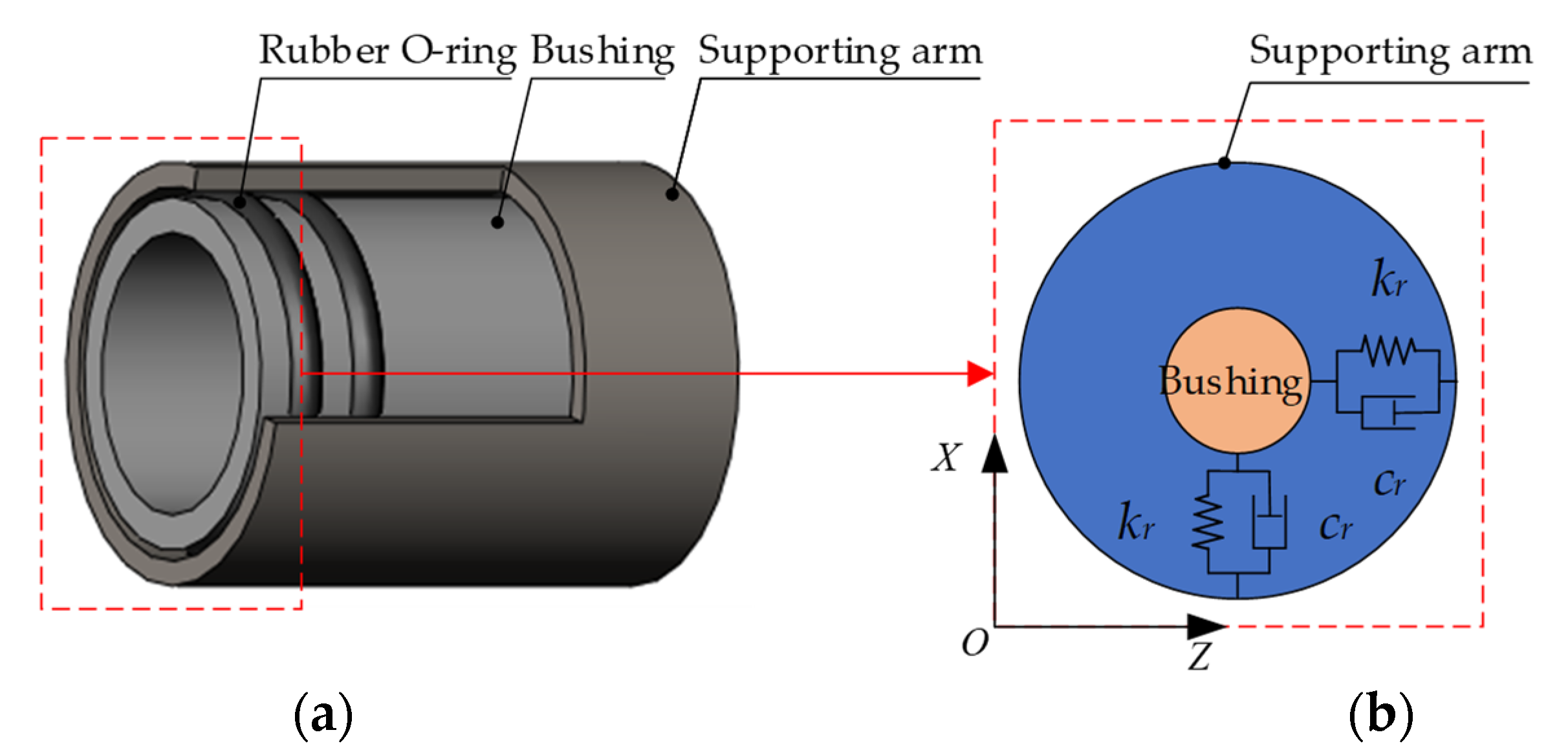
- Rubber O-Ring
- (2)
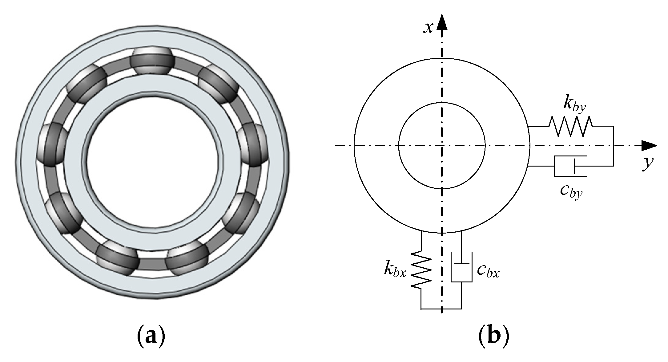
- Rolling Bearing
- (3)
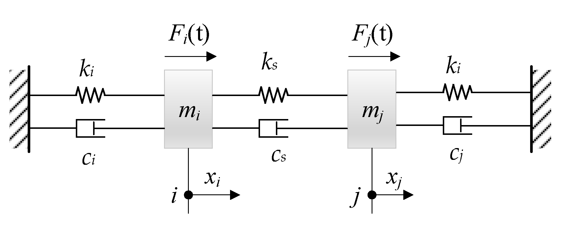
- Interference Connection
2.2.3. Dynamic Equations of Winding Rotor
2.3. Numerical Solution Algorithm
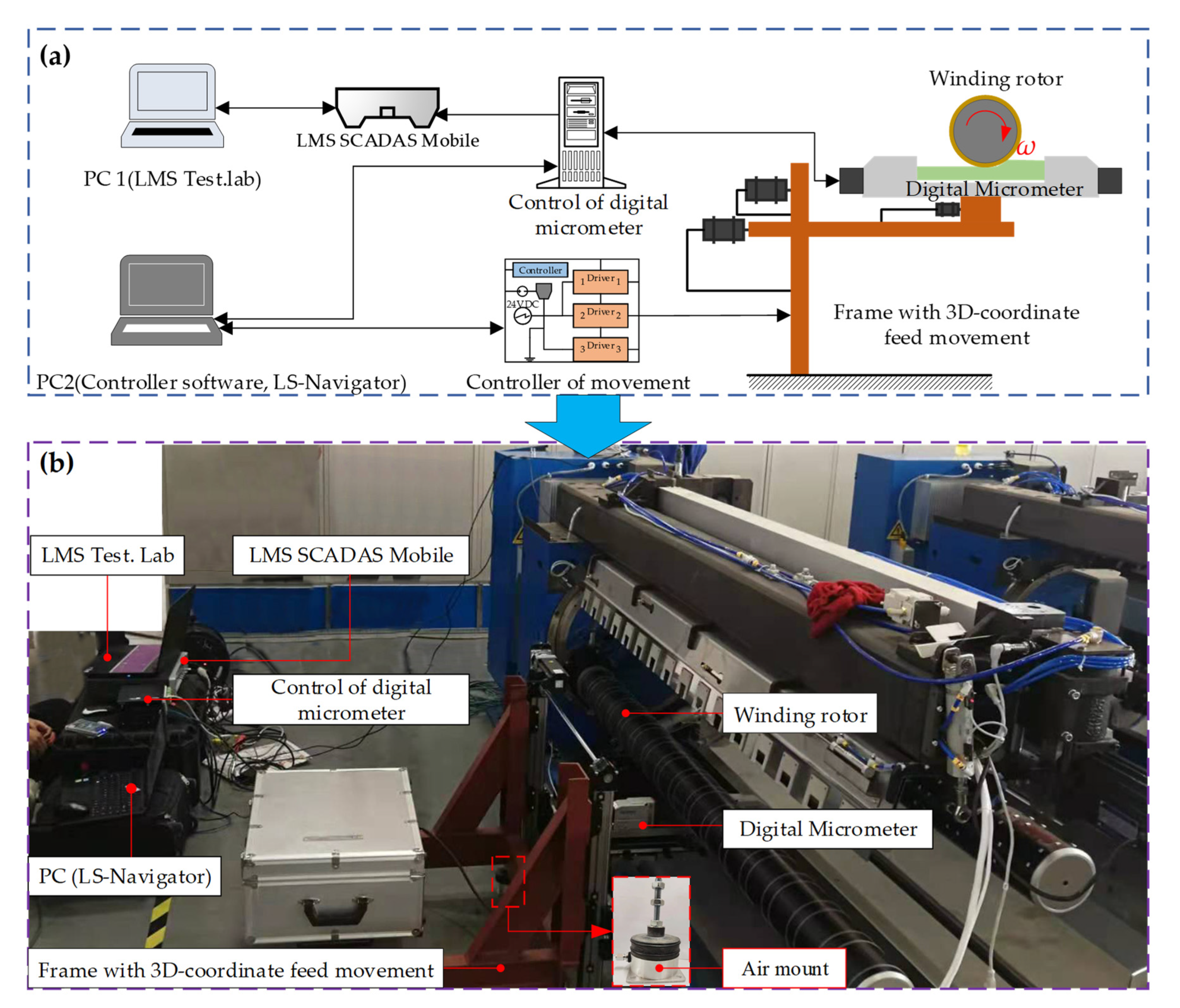
2.4. Measurement Device
3. Results and Discussion
3.1. Simulation and Experiment
3.1.1. Simulation Results
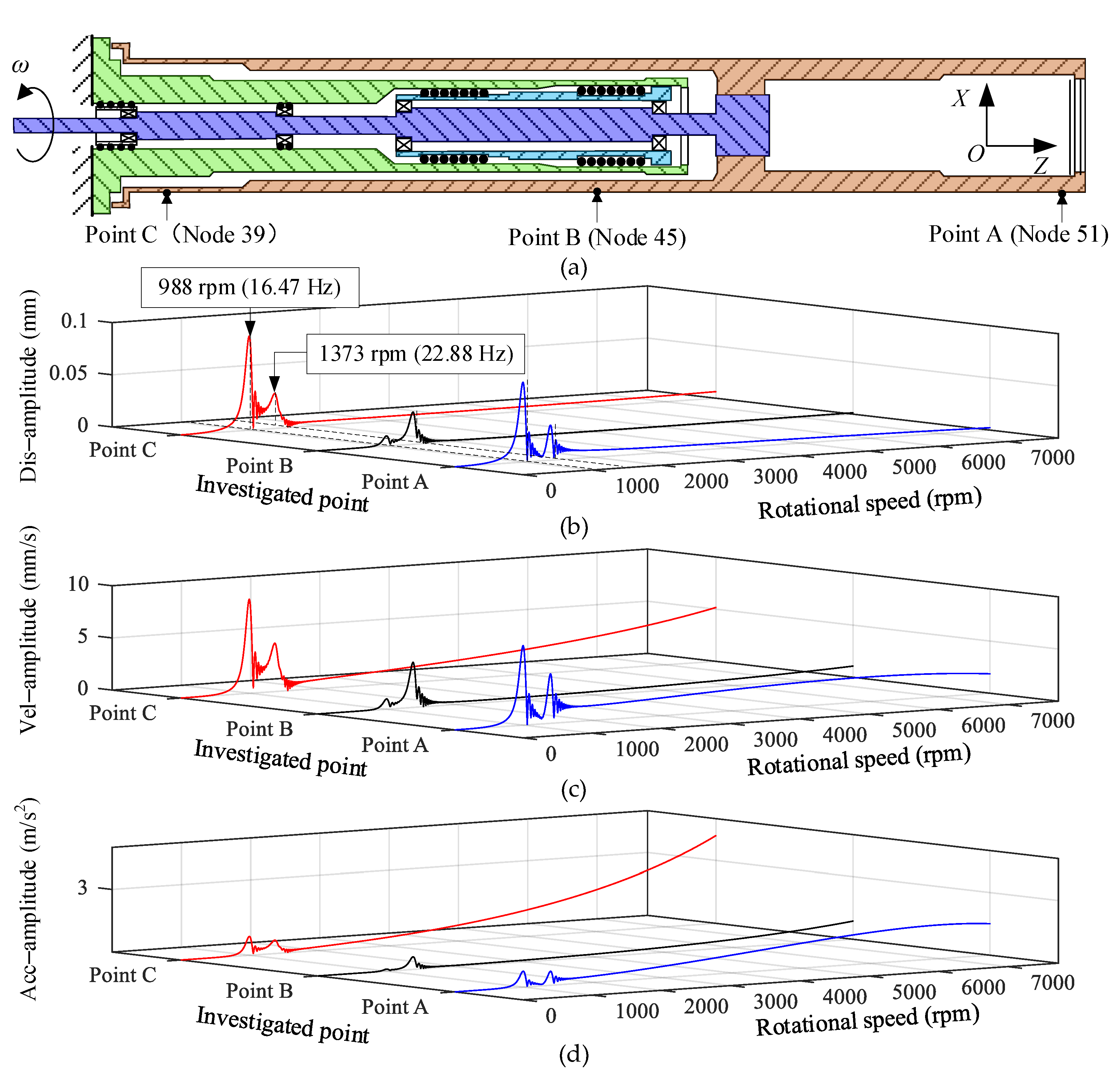
- During speeding up, two critical speed points of the winding rotor have appeared. The first-order and second-order critical speed points are mainly caused by the flexible support of the rubber O-ring. Meanwhile, taking into account the influence of automatic centering of the winding rotor, the investigated points have a larger vibration displacement amplitude. However, due to the low rotational speed and the short excitation time of the residual unbalanced force acting on the winding rotor, the acceleration amplitude of the investigated points is relatively small;
- As the rotational speed increases, the exciting force of the residual unbalance formed by the winding rotor becomes stronger, which causes the investigated points on the winding rotor to present a larger vibration displacement amplitude. As seen in Figure 11c,d, the velocity amplitude and acceleration amplitude of the three investigated points increase correspondingly. In addition, when the rotational speed of the rotor exceeds 2000 rpm and is less than 7730 rpm, the winding rotor has a small vibration amplitude and a high degree of stability.
3.1.2. Test Measurement
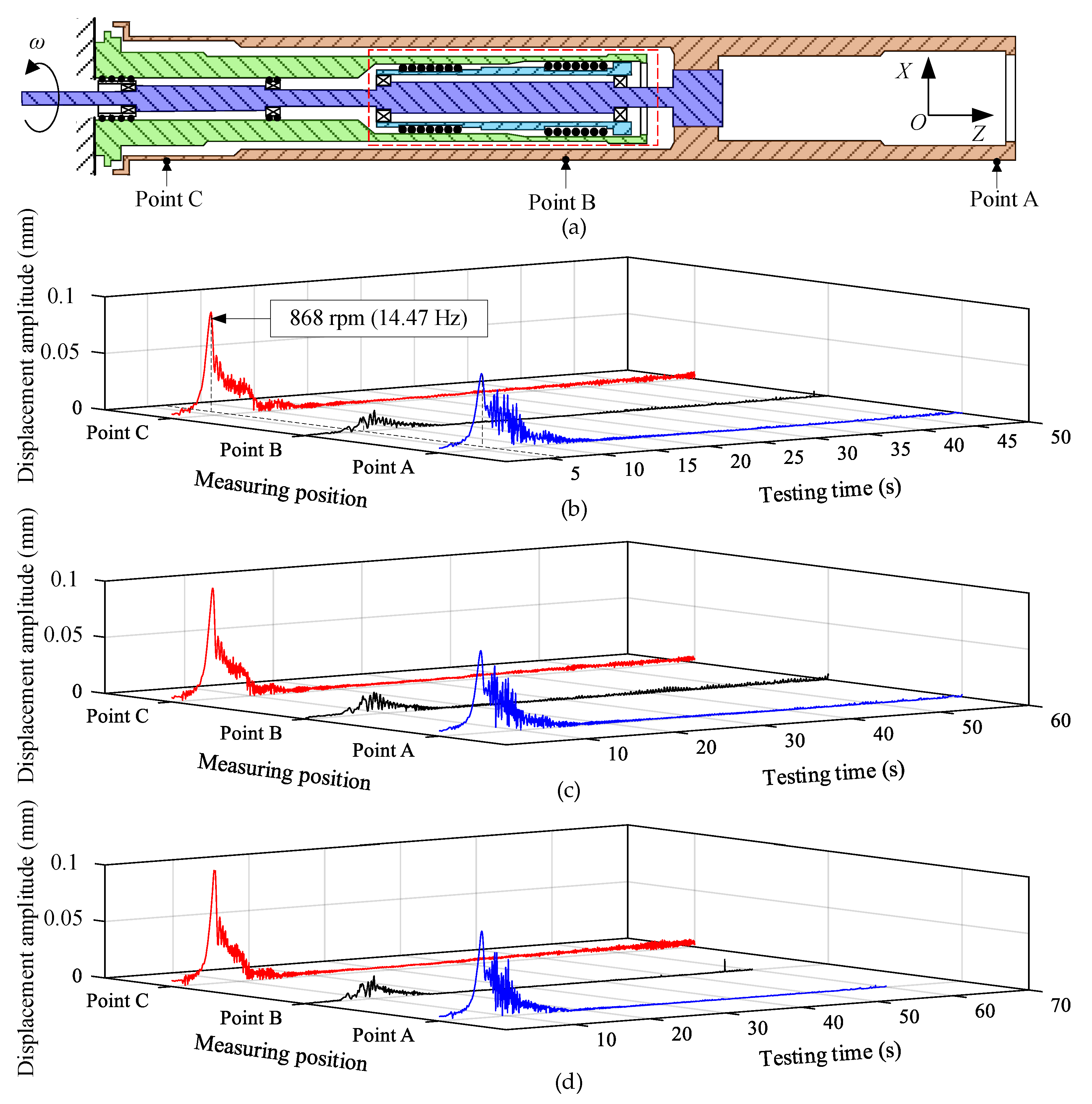
- The displacement amplitude of point B is smaller than that of point A and point C. It is mainly caused because the central position of the sleeve is supported by the supporting arm, as shown in Figure 12a. Due to the cantilever beam structure of the winding rotor and the supporting position of point B, the distance between point B and point C is larger than the distance between point B and point A, so the vibration displacement amplitude of point C is higher than that of point A near the first-order critical speed point;
- When the speed-up time is 60 s, comparing the simulation results shown in Figure 10b and experimental results shown in Figure 12c, showed that they are in good agreement, which verifies the correctness of the developed model of the winding rotor in this paper. However, the vibration amplitudes of the measured points are larger than that of the investigated points. The main reason is that the large vibration amplitude of the measured points was mainly due to the cylindricity error of the testing position on the sleeve and the greater residual unbalance of the winding rotor. In the same speed-up time, the maximum displacement amplitude is still in point C near the first-order critical speed point. Comparing different speed-up times, as the speed-up time increases, the vibration amplitude increases correspondingly: 0.0915 mm (speed-up time 50 s), 0.0962 mm (speed-up time 60 s) and 0.0997 mm (speed-up time 70 s). Similarly, points B and point C have the same characteristics.
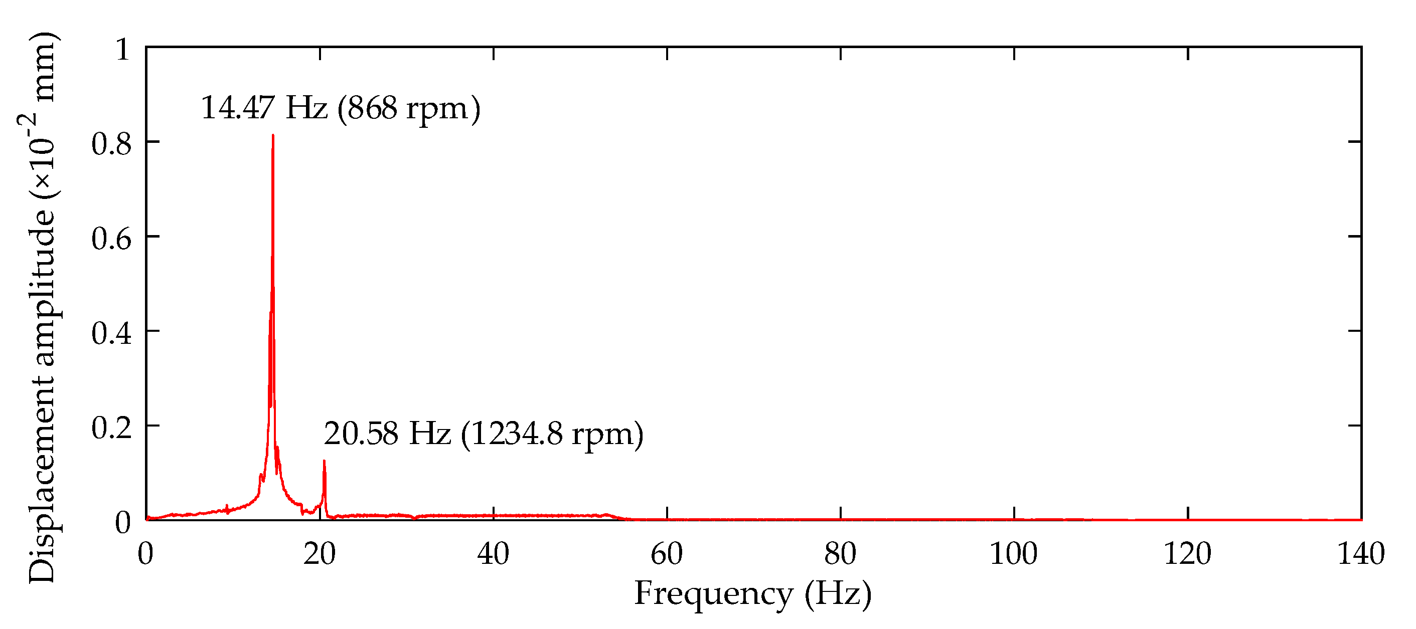
- During speeding up, it can be found that the rotational speed passes through the first-order critical speed point of the winding rotor based on the response amplitude. However, the vibration amplitude caused by passing through the second-order critical speed point cannot be clearly identified from Figure 12. To further analyze the experimental data, the frequency analysis of vibration data for the measured point C is performed under the speed-up time of 50 s, and the spectrum diagram is shown in Figure 13.
3.2. Discussion
3.2.1. Support without Rubber O-rings and Support with Rubber O-rings
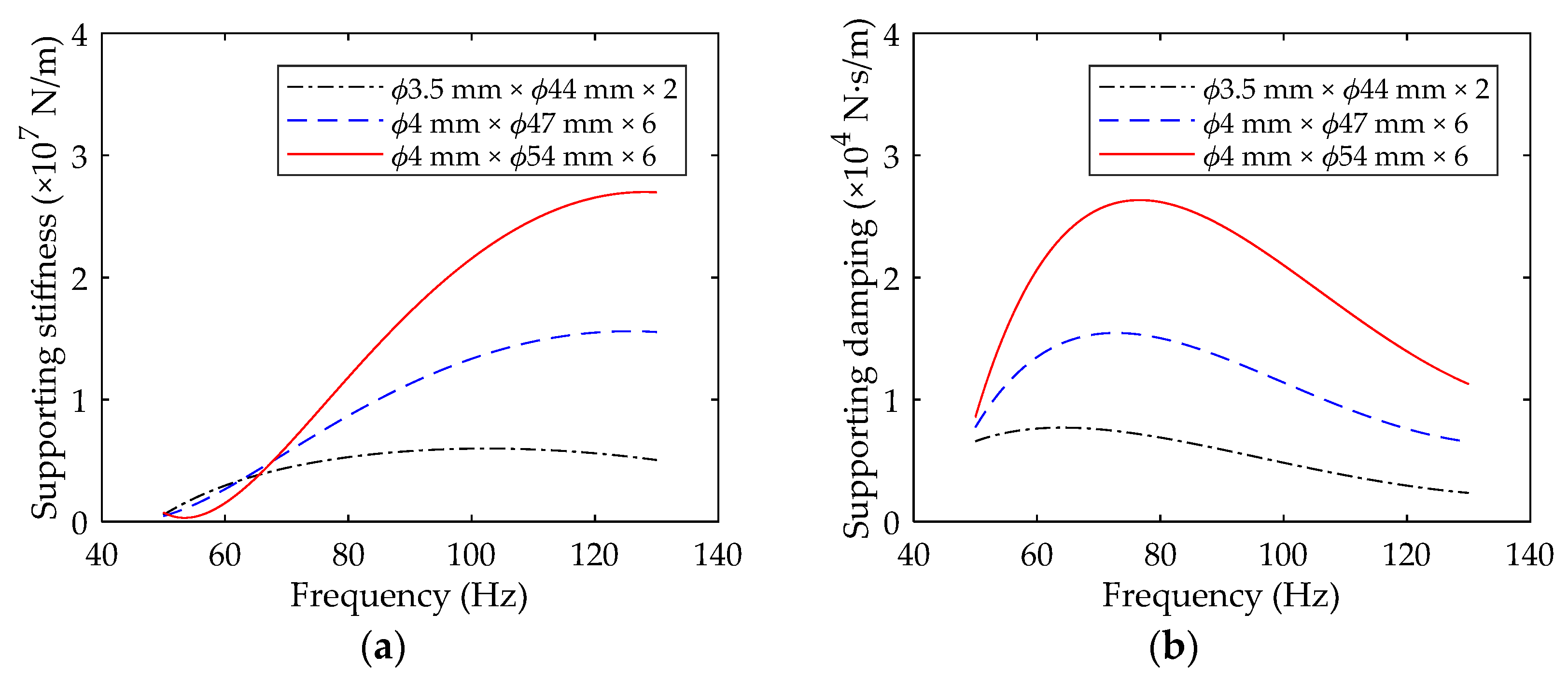
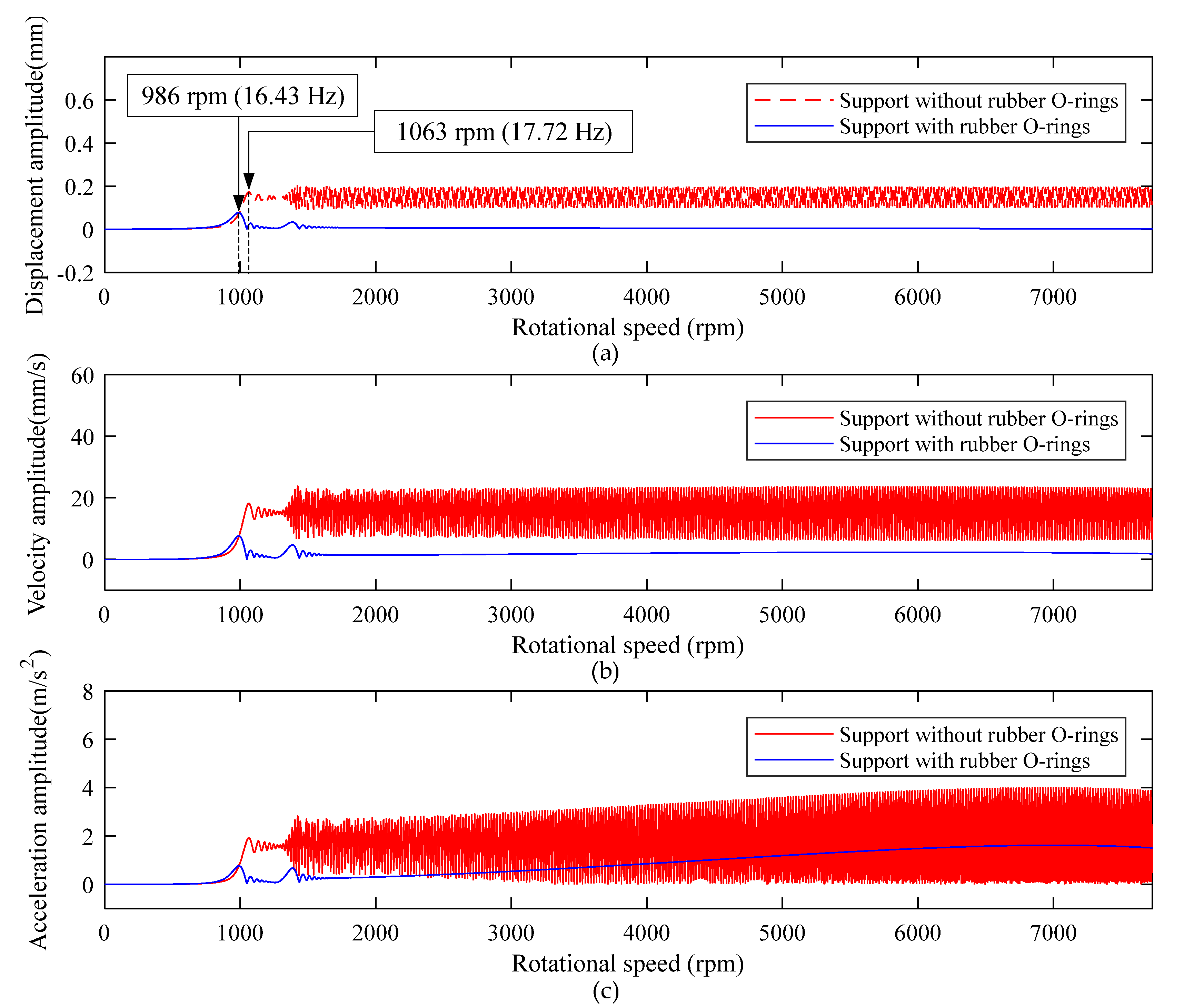
- The multiple rubber O-rings are installed in groups to form flexible support, and its equivalent overall supporting stiffness coefficient could reach the order of N/m, which is equal in the order of magnitude with the equivalent stiffness coefficient of the rolling bearings, as shown in Figure 8a. When the winding rotor adopts support with rubber O-rings, its first-order critical speed point is near 986 rpm. When the winding rotor adopts support without rubber O-rings, its first-order critical speed point is near 1063 rpm. The main reason for this is high stiffness through the interference connection, which leads to an increase in the critical speed of the rotor. In addition, when the rotational speed of the winding rotor is much lower than the first-order critical speed, the winding rotor with support without rubber O-rings and support with rubber O-rings both have relatively small vibration amplitude, as shown in Figure 14;
- As the rotational speed increases, the residual unbalance force acting on the rotor, including centrifugal force, increases correspondingly, which leads to the heavy vibration of the winding rotor when the rotational speed passes through the critical speed range. Especially after passing through the second-order critical speed, the winding rotor with support without rubber O-rings has constant heavy vibration. Due to the heavy vibration after passing through the second-order critical speed point, the winding rotor cannot work anymore in the textile process;
- When the winding rotor rotates within 7730 rpm, according to two different supports, the dynamic characteristics of the winding rotor are divided into two different parts by the first-order critical speed point. For the winding rotor with the support without rubber O-rings, as the residual unbalance force acting on the rotor increases, the displacement amplitude, velocity and acceleration amplitude of point A gradually increase. For the winding rotor with the support with rubber O-rings, the vibration amplitude increases slowly and the acceleration amplitude was stable after the rotational speed passing through the second-order critical speed point of the winding rotor;
- By contrast, the winding rotor with support with rubber O-rings has a very attractive dynamic character to control the vibration of the rotor system when rotational speed passes through the critical speed range.
3.2.2. Different Supporting Stiffness and Damping Coefficients of Rubber O-rings
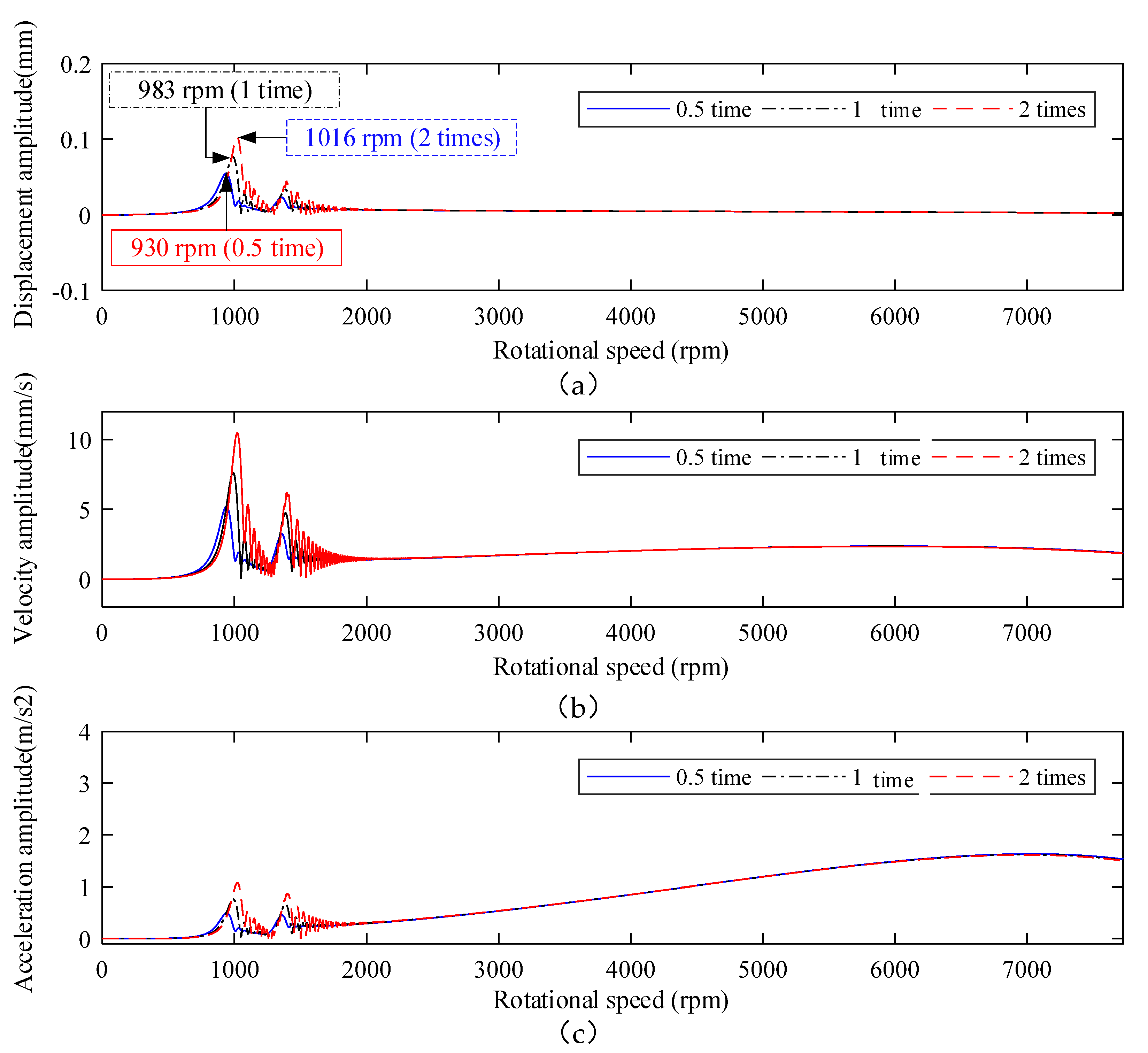
- Since the rubber O-rings are installed on the shaft in parallel, the stiffness value of supporting rubber O-rings increases with the increase of their number. Therefore, the critical speed point of the rotor is increased correspondingly, as shown in Figure 15a;
- Comparing with Figure 14, it can be seen that the flexible support effectively suppresses vibration of the winding rotor, and plays an important role in maintaining the system to pass through the critical speed points smoothly and rotate steadily in a wide working speed range. In addition, the winding rotor can rotate steadily in the wide working speed range under the equivalent coefficient of 0.5 time, 1 time and 2 times supporting parameters of the flexible support, which provides more rational choices for designing the flexible support structure and parameters.
- Appropriately increasing the values of supporting stiffness can effectively improve the supporting capacity of the winding rotor, but it will increase the vibration amplitude of the system.
3.2.3. Different Speed-Up Times
- During the rotational speed of the winding rotor passing through the critical speed of the winding rotor, when the speed-up time is short (30 s), the action time acting on the critical speed range is short, and the response amplitude is small. When the speed-up time increases (90 s), the action time that acts on the rotor’s critical speed range increases, that is, the action time that the external excitation force acts on the critical speed range increases, resulting in large amplitude and longer response time, as shown in Figure 16;
- Figure 16d shows, by shortening the speed-up time, that the acceleration amplitude can be reduced effectively, or even be crossed in some critical speed points with weak vibration. This study lays a solid foundation for providing the reference to design the working speed range and avoid the rotor working near its critical speed point. However, the winding rotor needs to install a high-power motor to shorten the speed-up time.
4. Conclusions
5. Patents
Author Contributions
Funding
Data Availability Statement
Conflicts of Interest
Nomenclature
| cross-section area of beam element | |
| damping matrix of system | |
| gyroscopic matrix of beam element | |
| damping of coupling connection | |
| global coupling matrix of contact damping | |
| global damping coupling matrix of rubber O-ring | |
| damping matrix of beam element of rubber O-ring | |
| equivalent damping coefficient of the rolling bearing | |
| equivalent damping coefficient of rubber O-ring, | |
| outer diameter of beam element cross-section | |
| inner diameter of beam element cross-section | |
| elastic modulus of structure steel | |
| node coordinate arrays of beam element | |
| , | forces acting on the node masses and , respectively |
| generalized force array of beam element | |
| gravity vector of system | |
| generalized force array of system | |
| gyroscopic moment matrix of system | |
| shear modulus of beam element | |
| second moment of inertia of beam element | |
| subscript, representing node | |
| global coupling matrix of contact stiffness | |
| global stiffness coupling matrix of rubber O-ring | |
| stiffness matrix of beam element of rubber O-ring | |
| transverse shear form factor | |
| stiffness matrix of beam element | |
| equivalent damping coefficient of bearing | |
| stiffness of coupling connection | |
| equivalent stiffness coefficient of rubber O-ring, | |
| unit length | |
| mass matrix of system | |
| mass matrix of beam element | |
| rotatory mass matrix | |
| translational mass matrix | |
| , | masses of node and , respectively |
| distance between node A and arbitrary point on the centerline | |
| time | |
| end time during deceleration | |
| end time during speeding up | |
| end time during winding | |
| , , | generalized arrays of displacement, velocity, acceleration |
| , , | generalized arrays of displacement, velocity and acceleration of element |
| displacement and velocity of node in the -axis direction | |
| displacement and velocity of node in the -axis direction | |
| displacement, velocity and acceleration of node | |
| angular displacement around -axis | |
| angular displacement around -axis | |
| angular displacement interpolation functions | |
| transverse shear effect | |
| linear displacement interpolation functions | |
| rotating angular velocity of winding rotor | |
| rotating angular matrix of system | |
| global coordinate frame | |
| local coordinate frame in beam element |
References
- Hung, J.P.; Lai, Y.L.; Luo, T.L.; Su, C.H. Analysis of the machining stability of a milling machine considering the effect of machine frame structure and spindle bearings: Experimental and finite element approaches. Int. J. Adv. Manuf. Tech. 2013, 68, 2393–2405. [Google Scholar] [CrossRef]
- Özsahin, O.; Özgüven, H.N.; Budak, E. Analytical Modeling of Asymmetric Multi-Segment Rotor—Bearing Systems with Timoshenko Beam Model Including Gyroscopic Moments. Comput. Struct. 2014, 144, 119–126. [Google Scholar] [CrossRef]
- Yu, P.C.; Zhang, D.Y.; Ma, Y.H.; Hong, J. Dynamic Modeling and Vibration Characteristics Analysis of the Aero-Engine Dual-Rotor System with Fan Blade Out. Mech. Syst. Signal Process. 2018, 106, 158–175. [Google Scholar] [CrossRef]
- Zhang, F.L.; Li, L.; Fan, Y.; Liu, J.Z. Dual-Connected Synchronized Switch Damping for Vibration Control of Bladed Disks in Aero-Engines. Appl. Sci. 2020, 10, 1478. [Google Scholar] [CrossRef] [Green Version]
- Liu, J.; Wang, C.; Luo, Z.W. Research Nonlinear Vibrations of a Dual-Rotor System with Nonlinear Restoring Forces. J. Braz. Soc. Mech. Sci. Eng. 2020, 42, 461. [Google Scholar] [CrossRef]
- Queguineur, M.; Bridel-Bertomeu, T.; Gicquel, L.Y.; Staffelbach, G. Large Eddy Simulations and Global Stability Analyses of an Annular and Cylindrical Rotor/Stator Cavity Limit Cycles. Phys. Fluids 2019, 31, 104109. [Google Scholar] [CrossRef]
- Xia, P.; Chen, H.; Liu, Z.S.; Ma, W.S.; Yang, B.F. Analysis of Whirling Motion for the Dynamic System of Floating Ring Seal and Rotor. Proc. Inst. Mech. Eng. Part J J. Eng. Tribol. 2019, 233, 1221–1235. [Google Scholar] [CrossRef]
- Chien, C.G.; Fung, R.F.; Tsai, C.L. Nonlinear Vibration of the Coupled Textile / Rotor System by Finite Difference Method. JSME Int. J. Ser. C 1999, 42, 273–280. [Google Scholar]
- Cveticanin, L. The Influence of the Reactive Force on the Motion of the Rotor on Which the Band Is Winding Up. J. Sound Vib. 1993, 167, 382–384. [Google Scholar] [CrossRef]
- Lund, J.W. The Stability of an Elastic Rotor in Journal Bearings with Flexible, Damped Supports. J. Appl. Mech. 1965, 87, 911–920. [Google Scholar] [CrossRef]
- Powell, J.W.; Tempest, M.C. A Study of High Speed Machines with Rubber Stabilized Air Bearings. J. Lubr. Technol. 1968, 90, 701–707. [Google Scholar] [CrossRef]
- Kazimierski, Z.; Jarzecki, K. Stability Threshold of Flexibly Supported Hybrid Gas Journal Bearings. J. Lubr. Technol. 1979, 101, 451–457. [Google Scholar] [CrossRef]
- Bttig, P.; Schiffmann, J. Data-Driven Model for the Dynamic Characteristics of O-Rings for Gas Bearing Supported Rotors. J. Appl. Mech. 2019, 86, 081003. [Google Scholar] [CrossRef]
- Wang, Y.X.; Zhang, L.J.; Hou, X.; Yan, J.; Li, S.J. A Dynamic Modeling Approach for the Winding Spindle During Start-up with a Coupled Flexible Support System. Text. Res. J. 2019, 90, 757–775. [Google Scholar] [CrossRef]
- Nelson, H. A Finite Rotating Shaft Element Using Timoshenko Beam Theory. J. Mech. Des. 1980, 102, 793–803. [Google Scholar] [CrossRef]
- Kalita, M.; Kakoty, K.S. Analysis of Whirl Speeds for Rotor-Bearing Systems Supported on Fluid Film Bearings. Mech. Syst. Signal. Process. 2004, 18, 1369–1380. [Google Scholar] [CrossRef]
- Dutt, J.K.; Nakra, B.C. Stability Characteristics of Rotating Systems with Journal Bearings on Viscoelastic Support. Mech. Mach. Theory 1996, 31, 771–779. [Google Scholar] [CrossRef]
- Nelson, H.D.; Mcvaugh, J.M. The Dynamics of Rotor-Bearing Systems Using Finite Elements. Trans. Am. Soc. Mech. Eng. J. Eng. Ind. 1976, 98, 593–600. [Google Scholar] [CrossRef]
- Zorzi, E.S.; Nelson, H.D. Finite Element Simulation of Rotor-Bearing Systems with Internal Damping. J. Eng. Gas. Turbines Power 1977, 99, 71–76. [Google Scholar] [CrossRef]
- Kang, Y.; Chang, Y.P.; Tsai, J.W.; Mu, L.H.; Chang, Y.F. An Investigation in Stiffness Effects on Dynamics of Rotor-Bearing-Foundation Systems. J. Sound Vib. 2000, 231, 343–374. [Google Scholar] [CrossRef] [Green Version]
- Abdesselam, L.; Guy, C. Study of Rotor Asymmetry Effects of an Induction Machine by Finite Element Method. J. Electr. Eng. Technol. 2011, 6, 342–349. [Google Scholar] [CrossRef] [Green Version]
- Taplak, H.; Parlak, M. Evaluation of Gas Turbine Rotor Dynamic Analysis Using the Finite Element Method. Measurement 2012, 45, 1089–1097. [Google Scholar] [CrossRef]
- Bin, G.; Li, X.; Wu, J.; Gao, J. Virtual Dynamic Balancing Method without Trial Weights for Multi-Rotor Series Shafting Based on Finite Element Model Analysis. J. Renew. Sustain. Energy 2014, 6, 130–136. [Google Scholar] [CrossRef]
- Lee, A.C.; Kang, Y.; Tsai, K.L.; Hsiao, K.M. Transient Analysis of an Asymmetric Rotor-Bearing System During Acceleration. J. Eng. Ind. 1992, 114, 465–475. [Google Scholar] [CrossRef]
- Lee, A.S.; Kim, B.O.; Kim, Y.C. A finite element transient response analysis method of a rotor-bearing system to base shock excitations using the state-space Newmark scheme and comparisons with experiments. J. Sound Vib. 2006, 297, 595–615. [Google Scholar] [CrossRef]
- Kim, B.S.; Lee, S.H.; Lee, M.G.; Ni, J.; Song, J.Y.; Lee, C.W. A comparative study on damage detection in speed-up and coast-down process of grinding spindle-typed rotor-bearing system. J. Mater. Process. Technol. 2007, 187, 30–36. [Google Scholar] [CrossRef]
- Yang, Q.; Li, L.; Zhao, Y.; Shu, P. Experimental Measurement of Axial Clearance in Scroll Compressor Using Eddy Current Displacement Sensor. Proc. Inst. Mech. Eng. Part C J. Mech. Eng. Sci. 2008, 222, 1315–1320. [Google Scholar] [CrossRef]
- Mirzaei, M.; Ripka, P.; Vyhnanek, J.; Chirtsov, A.; Grim, V. Rotational Eddy Current Speed Sensor. IEEE Trans. Magn. 2019, 55, 1–10. [Google Scholar] [CrossRef]
- Rao, J.S.; Shiau, N.T.; Chang, R.J. Theoretical Analysis of Lateral Response Due to Torsional Excitation of Geared Rotors. Mech. Mach. Theory 1998, 33, 761–783. [Google Scholar] [CrossRef]
- Wu, J.J. Free Vibration Analysis of Beams Carrying a Number of Two-Degree-of-Freedom Spring-Damper-Mass Systems. Finite Elem. Anal. Des. 2004, 40, 363–381. [Google Scholar] [CrossRef]
- Chiang, H.W.; Hsu, C.N.; Tu, S.H. Rotor-Bearing Analysis for Turbomachinery Single- and Dual-Rotor Systems. J. Propuls. Power 2004, 20, 1096–1104. [Google Scholar] [CrossRef]
- Chen, G. A New Rotor-Ball Bearing-Stator Coupling Dynamics Model for Whole Aero-Engine Vibration. J. Vib. Acoust. 2009, 131, 061009. [Google Scholar] [CrossRef] [Green Version]
- Newmark, N.M. A Method of Computation for Structural Dynamics. J. Eng. Mech. Div. ASCE 1959, 85, 67–94. [Google Scholar] [CrossRef]


| ID | Type | Model | Sensitivity |
|---|---|---|---|
| 1 | Keyence digital micrometer | LS-9000 | ±2 μm |
| 2 | LMS SCADAS Mobile | SCM201V | / |
| ID | Label | Value | Unit |
|---|---|---|---|
| 1 | Supporting arm length | 1230 | (mm) |
| 2 | Shaft length | 1340 | (mm) |
| 3 | Sleeve length | 1780 | (mm) |
| 4 | Outer diameter of sleeve | 107 | (mm) |
| 5 | Interference coupling length | 75 | (mm) |
| 6 | Bearing support span between Ⅰ and Ⅱ | 380 | (mm) |
| 7 | Bearing support span Ⅲ | 400 | (mm) |
| 8 | Support flexible Ⅰ | 15 | (mm) |
| 9 | Support flexible Ⅱ | 30 | (mm) |
| 10 | Support flexible Ⅲ | 505 | (mm) |
| 11 | Maximum rotational speed of winding rotor | 7730 | (rpm) |
| 12 | Number of rear bearings | 2 | (set) |
| 13 | Number of front bearings | 2 | (set) |
| 14 | Mass of shaft | 8.66 | (kg) |
| 15 | Mass of sleeve | 47.19 | (kg) |
| 16 | Mass of supporting arm | 19.38 | (kg) |
| 17 | Mass of support flexible Ⅰ | 1.6 | (kg) |
| 18 | Mass of support flexible Ⅱ | 3.0 | (kg) |
| 19 | Mass of support flexible Ⅲ | 4.5 | (kg) |
| 20 | Unbalance of node 30 | 1.42 × 10⁻⁵ | (kg·m) |
| 21 | Unbalance of node 46 | 7.41 × 10⁻⁵ | (kg·m) |
Publisher’s Note: MDPI stays neutral with regard to jurisdictional claims in published maps and institutional affiliations. |
© 2021 by the authors. Licensee MDPI, Basel, Switzerland. This article is an open access article distributed under the terms and conditions of the Creative Commons Attribution (CC BY) license (https://creativecommons.org/licenses/by/4.0/).
Share and Cite
Ma, X.; Li, S.; Tian, W.; Qu, X.; Wang, S.; Wang, Y. Dynamic Behavior Analysis of the Winding Rotor with Structural Coupling and Time-Frequency Varying Parameters: Simulation and Measurement. Appl. Sci. 2021, 11, 8124. https://doi.org/10.3390/app11178124
Ma X, Li S, Tian W, Qu X, Wang S, Wang Y. Dynamic Behavior Analysis of the Winding Rotor with Structural Coupling and Time-Frequency Varying Parameters: Simulation and Measurement. Applied Sciences. 2021; 11(17):8124. https://doi.org/10.3390/app11178124
Chicago/Turabian StyleMa, Xunxun, Shujia Li, Wangliang Tian, Xiqiang Qu, Shengze Wang, and Yongxing Wang. 2021. "Dynamic Behavior Analysis of the Winding Rotor with Structural Coupling and Time-Frequency Varying Parameters: Simulation and Measurement" Applied Sciences 11, no. 17: 8124. https://doi.org/10.3390/app11178124
APA StyleMa, X., Li, S., Tian, W., Qu, X., Wang, S., & Wang, Y. (2021). Dynamic Behavior Analysis of the Winding Rotor with Structural Coupling and Time-Frequency Varying Parameters: Simulation and Measurement. Applied Sciences, 11(17), 8124. https://doi.org/10.3390/app11178124