Article

Laser-Based, Optical, and Traditional Diagnostics of NO and Temperature in 400 kW Pilot-Scale Furnace

1
RISE Energy Technology Center, Box 726, SE-941 28 Piteå, Sweden
2
Luossavaara-Kiirunavaara AB, Box 952, SE-971 28 Luleå, Sweden
*
Author to whom correspondence should be addressed.
Appl. Sci. 2021, 11(15), 7048; https://doi.org/10.3390/app11157048
Submission received: 15 June 2021 / Revised: 16 July 2021 / Accepted: 21 July 2021 / Published: 30 July 2021

Abstract

:
A fast sensor for simultaneous high temperature (above 800 K) diagnostics of nitrogen oxide (NO) concentration and gas temperature (T) based on the spectral fitting of low-resolution NO UV absorption near 226 nm was applied in pilot-scale LKAB’s Experimental Combustion Furnace (ECF). The experiments were performed in plasma and/or fuel preheated air at temperatures up to 1550 K, which is about 200 K higher than the maximal temperature used for the validation of the developed UV NO sensor previously. The UV absorption NO and T measurements are compared with NO probe and temperature measurements via suction pyrometry and tuneable diode laser absorption (TDL) using H2O transitions at 1398 nm, respectively. The agreement between the NO UV and NO probe measurements was better than 15%. There is also a good agreement between the temperatures obtained using laser-based, optical, and suction pyrometer measurements. Comparison of the TDL H2O measurements with the calculated H2O concentrations demonstrated an excellent agreement and confirms the accuracy of TDL H2O measurements (better than 10%). The ability of the optical and laser techniques to resolve various variations in the process parameters is demonstrated.

1. Introduction

Electro fuels (plasma torch, hydrogen) are considered as a possible replacement for fossil fuels in heavy process industries’ combustion processes in Sweden, due to a large amount of renewable electricity production from hydro and wind power. It is important to ensure that the replacement of fossil fuels would not worsen both the combustion/heating performance of the sustainable system and pollutant emission, in particular NOx. Due to the complexity of the practical processes, it is often difficult to predict how changes in fuel and process parameters will influence the performance of the plant. Therefore, accurate experimental data, especially from inside the furnace, that provide reliable information on the temperature and concentrations of the major species and pollutants are of great value. At present, optical and laser-based absorption spectroscopy is one of the most promising and rapidly developing technologies applied in thermochemical conversion systems for online and in situ diagnostics [1,2,3]. The most important advantages of the optical and laser-based methods are that they are non-invasive, rapid (the millisecond temporal resolution is routinely attainable), low-cost, calibration-free, and capable of detecting in high-temperature and dusty environments with limited optical access. The optical ultraviolet (UV) absorption near 226 nm was successfully applied for NO diagnostics at high-temperature conditions, see for example [3,4,5,6,7].
This paper describes the application of the UV absorption (NO concentration and T) and TDL (H2O concentration and T) measurement set-ups in trials performed in a 400-kilowatt pilot-scale test facility–ECF designed to mimic a burner port in one of LKAB’s straight grate iron-ore induration machines [8]. The campaign goal was to investigate the effects of the replacement of fossil oil (FO) by electro fuels (plasma torch and H2) on energy efficiency and emissions. This paper focuses on demonstrating the performance of non-intrusive set-ups for the characterization of the process parameters in long-term tests and to discuss the benefits and shortcomings of the methods for a better understanding and control of the process. The optical and laser-based sensors were developed earlier by RISE ETC [9,10,11] and applied for diagnostics of lab-sale and pilot-scale, up to 150 kW, high-temperature processes. The optical measurements are compared with those from the traditional equipment. The work extends a range of the applicability of the NO UV absorption method for simultaneous diagnostics of NO and T for both T and the NO column density. The maximal temperature in ECF experiments was 200 K higher than that reported in lab-scale research [9] ~1350 K, while the maximum NO column density was increased by a factor of 1.8 in the ECF experiments.

2. Materials and Methods

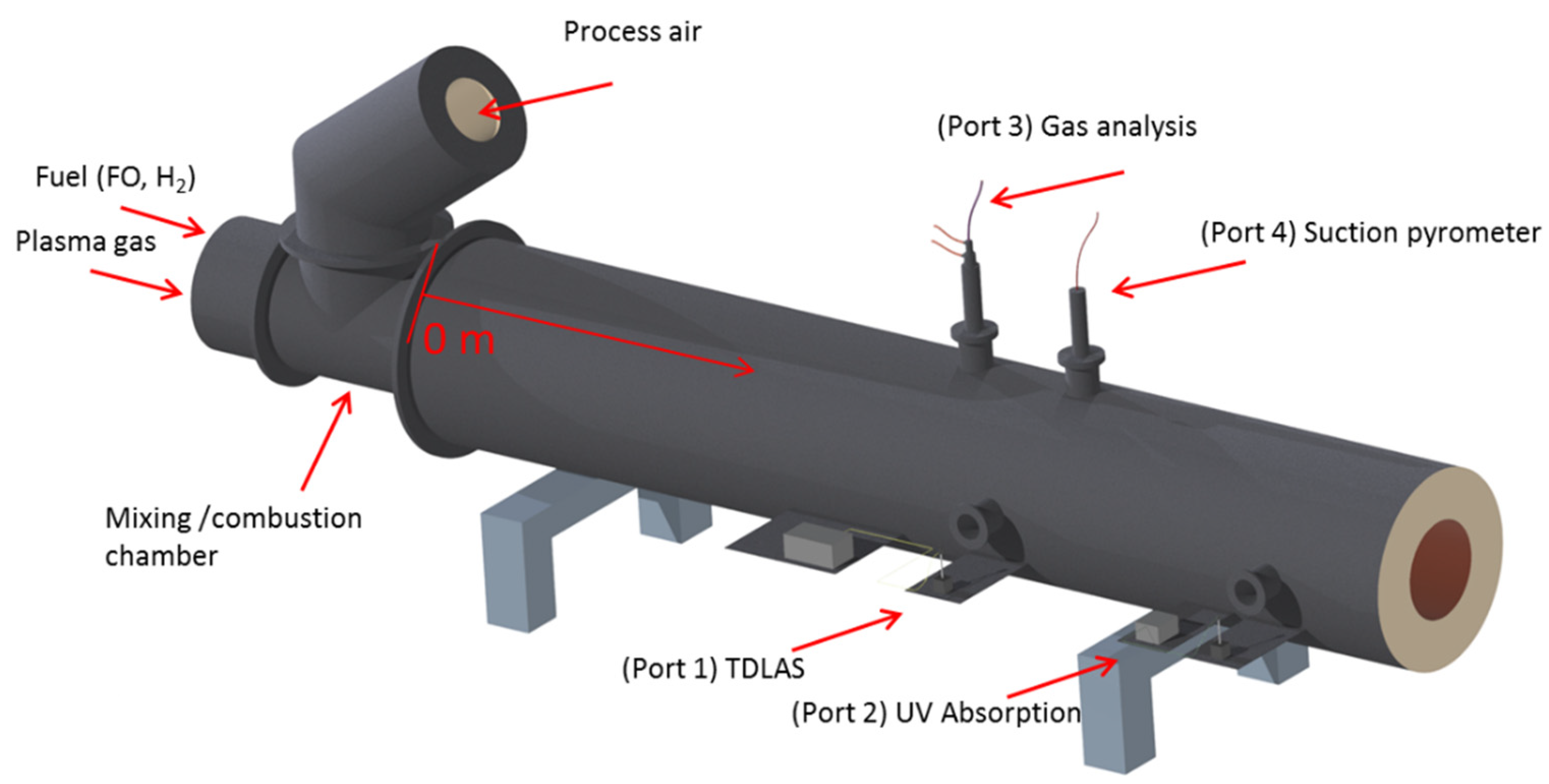
2.1. Experimental Combustion Furnace (ECF)

The heating of process air in the mixing chamber was made by FO, H2 combustion and/or mixing with hot plasma gases, see Figure 1. The experiments were performed in a 400 kW ECF at LKAB in Luleå, Sweden. The ECF was designed with a 200-millimeter-thick refractory and a length of 14 m. Outside the refractory, a layer of insulation protects the outer steel shell. The inner diameter of the refractory is about 65 cm in the first part of the ECF and is about 80 cm in the second one. Two optical ports, P1 and P2, located 420 and 620 cm from the beginning of the ECF were used in the reported optical experiments. The optical ports were designed with N2 flushing, similar to that reported in [12], to prevent the intrusion of furnace gases into the port extensions. Below, the optical path lengths at P1 and P2 are considered equal to the ECF inner diameter at the given locations. Ports P3 and P4 located at 447 and 370 cm were used for traditional measurements of temperature and concentrations.

2.2. Non-Intrusive and Traditional Diagnostics

TDLAS was used for the measurements of H2O and T at port P1, see Figure 1. The UV absorption measurements of T and NO were made at port P2. The distance between P1 and P2 is 200 cm. The path length of the measurements is 65 and 78.5 cm at P1 at P2, respectively, and the inner diameter of the ECF is gradually increases between the ports.
A detailed description of the TDLAS system at 1398 nm and the method for the evaluation of temperature and H2O concentration can be found in our previous studies [10,11]. In brief, the laser wavelength from a fiber-coupled distributed feedback laser (Nanoplus GmbH) was controlled by a laser diode/TEC controller (ITC4001, Thorlabs). The laser was tuned over a range of up to ∼3 cm−1 via the 100 Hz triangular modulation of the driving current produced by a data acquisition system from National Instruments with a NI PXIe-6356 card. The modulation was made at a constant diode temperature of 41 °C. After passing through the ECF, the light was focused on a photodetector (PDA10, Thorlabs). Temperatures and H2O concentrations were determined by least-squares fitting of the measured absorption spectra using spectral line parameters from the HITRAN 2012 [13] and HITEMP [14] databases reported in [10]. Information on the temperature-dependent self-broadening coefficient nself was taken from [15]. For the experimental conditions studied, the uncertainty of TDL H2O measurements is about ±10% (relative) and TDL T is about ±50–60 °C for H2O volume fraction above 1.5 vol-%, at lower H2O concentration the uncertainty might increase.
The general description of the NO UV absorption measurements and the procedure of the data treatment is given in [9]. In short, fiber-coupled radiation from a high-brightness deuterium lamp of 9 W (Hamamatsu L10290) was used as a broadband UV light source. The UV radiation from the 600-micrometer diameter fiber was collimated using a short focus convex lens to produce a beam with an initial diameter of about 1 cm. The beam passed through ECF at P2, the beam diameter at the P2 outlet was about 2 cm. The beam was focused onto an optical fiber coupled to a UV–VIS range highspeed spectrometer (Ocean Optics HR2000 + GC) with a diffraction grating (Ocean optics, HC-1 Grating, 600 g/mm, blazed at 300 nm). The absorption spectra were recorded with a rate of 10 spectra per second, 100 spectra were typically averaged. The background signals were recorded during the fuel feeding stoppages/interruptions. The fitting of the experimental spectra was made using the well-known constants for (0, 0), (1, 1), and (2, 2) NO vibrational transitions of the A2Σ+X2Π2 electronic system. To reduce the computational time, a library of the molecular spectra calculated from 1300 to 1600 K with a step of 20 K was created. The uncertainty of the UV broadband absorption NO and T measurements determined for T < 1350 K is about ±15% (relative) and ±50 °C, respectively.
A suction pyrometer used for in-flame temperature measurement is installed in port P3, located 447 cm from the beginning of the ECF. The pyrometer consisted of a type B thermocouple (rated to 1750 °C) inside a ceramic sheath, with a ceramic radiation shield around the thermocouple junction. Limas 11 analyzer (ABB) was used for online measurements of NO (0–1000 ppm UV and 0–10000 ppm infra-red modules) and NO2 (0–1000 ppm UV module) in port P4, located 370 cm from the beginning of the ECF.
The traditional analyzers reported a continuous stream of process data, which was available for operators in real time, while the optical and laser measurements are the result of the data aftertreatment.

3. Results and Discussion

As an example, Figure 2, Figure 3, Figure 4 and Figure 5 show real-time optical, laser-based, and conventional measurements of the process parameters in the experiments for heating up the process gas by FO, H2, N2 plasma, and Air plasma + H2, respectively. Figure 2a, Figure 3a, Figure 4a and Figure 5a show the temperature measured inside the ECF using the TDL and UV NO absorption techniques at P1 and P2 and suction pyrometer at P3 and the TC measurement of the process air before the mixing/combustion chamber. Figure 2b, Figure 3b, Figure 4b and Figure 5b demonstrate the volumetric flow rate of the coflow air and the fuel, plasma power, and, when available, the TDL H2O measurements and the H2O calculations made based on the air and fuel flows. Figure 2c, Figure 3c, Figure 4c and Figure 5c present the NO and NO2 concentrations measured by the optical and probe diagnostics.
Due to the large amount of data shown in the figures, it is reasonable to start with describing the features of the air flow and temperature that are common for all the measurements. The flow rate of the process air, being on average 2180 m3/h, has variations of type I and II, see Figure 2b, Figure 3b, Figure 4b and Figure 5b. The I type of the variations manifests itself by the rapid decrease and increase in the air flow by ~5% occurring every 21 min. This type of variation is due to the regular switching of the process air flow from one to another gas-fired pebble heater. The variations of the II type are periodic with a period of several minutes coming from air flow control system.
The process air temperature is measured by a bare TC is about 1230 K; the TC temperature shows regular increases in the temperature of 7–8 K matching the I type of variations; reducing the process air flow through the pebble heaters increases the air temperature. The II type of the variations is not noticeable in the TC temperature measurement, since the magnitude of the II type variations is several times lower than that of the I type. The TDL and suction pyrometer data, Figure 2a, Figure 3a, Figure 4a and Figure 5a, reflect the variations of the I type by showing the temperature increases by several K at times when the switching of the process air flow from one to another gas-fired pebble heater occurs. The II type of the variations is not resolved by the TDL measurements. The suction pyrometer measurements have better sensitivity than the TDL ones to this type of variation, see Figure 5a. The temperature measured using the UV NO absorption does not show increases in this type, we remind that the method uses the precalculated spectra simulated with the temperature step of 20 K.
Apart from the small variations of the II type, the temperature of the process air was constant. The temperatures measured using the UV NO absorption, TDL, and suction pyrometer, in general, reflect the effects of the process air heating due to fuel combustion and/or mixing with hot plasma gases. For example, the TDL and suction pyrometer temperatures (Figure 2a) follow the trend of the FO flow (Figure 2b), since at fuel-lean combustion, there is a practically linear dependence between the equivalence ratio proportional to fuel flow and the temperature. The difference between the TDL and suction pyrometer temperatures was about 60 K for most of the shown data points and was about 40 K in general during the FO combustion, which is very good considering the uncertainties of the methods. We note that the laser-based and optical methods report the path- averaged values, while standard probes report the data from a point.
For other fuels or plasma heating, the difference between the TDL and pyrometer measurements was around 100 K; the somewhat larger difference in Figure 3a between 8:00 and 13:00 is because the pyrometer was located closer to the wall, the temperature of which is lower than that of the gas. The TDL and UV NO absorption temperatures were, in general, within 50 K; the TDL temperature was higher than the NO UV one. Accounting for the heat losses of gas between the TDL and NO UV positions, 2 m, might improve the agreement.
The TDL diagnostics is more responsive to the fast variations in gas temperature than the suction pyrometer detection, for example, the fuel feeding interruption results in the immediate decline of the TDL temperature, while the suction pyrometer requires some minutes to register the decline, see Figure 6 showing online measurements of T (TDL, suction pyrometer, TC) and H2O (TDL) during the FO combustion. The reason for the above is that the TDL measures the gas temperature, while the suction pyrometer measures the temperature of the thermocouple tip, which might be affected by the radiation from combusting fuel, particles, gas products, and walls. Figure 2b, Figure 3b and Figure 5b include the TDL H2O measurements; there is a quite clear and intuitively correct correlation between the H2O measurements, and all the variations in the air and fuel flows discussed above. Furthermore, the H2O measurements show distinct variations of the type III coming from the rapid periodical fluctuations of the H2 flow rate, see Figure 3b. Later in the campaign, these rapid fluctuations in the H2 flow were reduced by narrowing the range between the upper and lower limits of the flow controller settings for a given flow rate. The measured and calculated H2O volume fractions for H2 combustion shown in Figure 3b are in excellent agreement with each other. The same can be said about all the H2 combustion/plasma heating experiments made in the tests. The agreement between the measured and calculated H2O volume fraction for FO combustion is also very good, better than 8%. The TDL H2O sensor’s ability to accurately detect fluctuations in the air and fuel flows offers interesting opportunities for the implementation of the technique for diagnostics and the control of industrial processes. For example, the TDL H2O measurements can be used to control the overall air-fuel equivalence ratio and determine the degree of the air leakages.
The NO mole fractions obtained using the NO UV absorption and the probe measurements correlate well with each other and the variations in the air and fuel flows. There is a 15% difference between the NO measurement methods for H2 and FO combustion and a 10% one for the plasma heating experiments, which we consider as rather good considering the uncertainties in the NO UV absorption and probe measurements. In the evaluation of the NO mole fraction using the NO UV absorption method made for FO combustion, the temperature measured using the TDL was used. At the conditions studied, an increase in the input temperature by 100 °C results in a decrease in the NO mole fraction by approximately 10%. For H2 and FO combustion, the NO2/NOx ratio is below 10%, which is in accordance with a typical NO2/NOx ratio for combustion, see [16]. In plasma heating experiments, the significant concentrations of NO2 were measured using the probe up to 1000 ppm, the NO2/NOx ratio is above 25%. The UV spectra recorded in the ECF do not contain any clear indication of the NO2 spectral features, similar to our earlier observation reported in [9].
Figure 7a–c show the examples of the experimental and fitted UV NO spectra for the cases when the process air was heated by H2-air combustion, N2 plasma, and Air plasma gases, respectively. The fitted NO and T values are reported in the figures. The agreement between the fitting and experimental spectra is rather good, though the experimental spectra display some disturbances occurring at about the same wavelengths for all the measured spectra. Figure 8 shows the transmission spectra near 225 nm measured when the process air was heated by Air Plasma gases (I) and when only the process air was in the ECF, I0. The dark current is included in the figure. The I0 signal decreases quickly with a decreasing the wavelength and displays wavelength-dependent features. In the evaluation, the “real” background signal I0, measured during the interruption/stoppage of the fuel feeding, is assumed to represent the “true” background absorbance (difference in the net absorption of the NO molecules and the measured gross absorbance) during the recording of the transmission signal, I. However, the somewhat different experimental conditions inside the ECF during I and I0 measurements lead to the deviation between “real” and “true” I0 signals, which causes the observed disturbances in the experimental spectra. The disturbances are more pronounced at low absorptance. The mismatch described above between “real” and “true” I0 signals prevented us from evaluating the temperature for FO combustion, characterized by relatively low NO concentration, below 200 ppm. Since the temperature depends on the shape of the NO UV spectra, the spectral disturbances at small signals were too high to allow an accurate evaluation. The NO concentration depends on the area under the spectral curve and was determined for all the measured cases. In our future work, we plan to modify the current NO UV absorption set up for improving the diagnostics of a low NO concentration in hot mixtures. First, the signal-to-noise ratio of the set-up and steepness of the I0 spectral dependence in the region of the NO absorption feature will be improved by selecting a more powerful D2 lamp and using the grating with better transmittance properties for NO diagnostics. Second, we plan to reduce the diameter of the UV beam by using extra optical lenses in a UV beam collimating system and/or by coupling the radiation from the UV source to a fiber with a diameter lower than 600 μm. Thirdly, the effects of the thickness and material of optical windows on matching “real” and “true” I0 signals will be attended.
Figure 9 shows an overview of the NO measurements made during the campaign; the NO mole fraction obtained using the NO UV absorption is plotted as a function of the probe NO. The line represents the NO probe values plotted versus itself. All the reported values were measured at ECF temperatures between 1350 and 1550 K, the experiments reported extends a range of the applicability of the NO UV absorption method for simultaneous diagnostics of NO and T from 1350 K reported in [9] to 1550 K. The maximum NO column density (NOxL, where L is the path length of the measurements) was increased by a factor of 1.8 in the ECF experiments (3800 ppm × 78 cm) in comparison with the maximum values in the lab-scale measurements (6500 ppm × 25 cm) at 1350 K.

4. Conclusions

The work demonstrated the performance of optical and laser techniques for the diagnostics of species (H2O, NO) and T in the pilot-scale processes, mimicking the LKAB burner system for pellet induration. The application of these techniques helped characterize the process behaviour for the three heating methods (FO, H2, plasma) and detect and explain the process-related variations. The comparison of the TDL H2O measurements with the calculated H2O concentrations demonstrated the excellent agreement, better than 10%. The range of the applicability of the NO UV absorption method for simultaneous diagnostics of NO and T was increased by 200 K from 1350 to 1550 K. A very good agreement, better than 15%, between the NO measurements made using the UV NO and probe methods was found. The laser-based (TDL) and optical (UV NO absorption) temperatures were, in general, within 50 K.

Author Contributions

Experimental concept, A.S., C.F. and H.W.; experimental realization and data collection, A.S., C.F. and Y.Ö.; writing—original draft preparation, A.S.; writing—review and editing, A.S., C.F., Y.Ö. and H.W. All authors have read and agreed to the published version of the manuscript.

Funding

This work has been conducted as part of the HYBRIT research project RP1. We gratefully acknowledge financial support from the Swedish Energy Agency through HYBRIT (Hydrogen Breakthrough Ironmaking Technology) and 50470-1 projects. HYBRIT is a joint initiative of the three companies SSAB, LKAB and Vattenfall with the aim of developing the world’s first fossil-free ore-based steelmaking route.

Institutional Review Board Statement

Not applicable.

Informed Consent Statement

Not applicable.

Data Availability Statement

Data supporting the results of this work can be obtained from the corresponding author upon reasonable request.

Conflicts of Interest

The authors declare no conflict of interest.

References

  1. Bolshov, M.A.; Kuritsyn, Y.A.; Romanovskii, Y.V. Tunable Diode Laser Spectroscopy as a Technique for Combustion Diagnostics. Spectrochim. Acta Part B At. Spectrosc. 2015, 106, 45–66. [Google Scholar] [CrossRef]
  2. Goldenstein, C.S.; Spearrin, R.M.; Jeffries, J.B.; Hanson, R.K. Infrared Laser-Absorption Sensing for Combustion Gases. Prog. Energy Combust. Sci. 2017, 60, 132–176. [Google Scholar] [CrossRef] [Green Version]
  3. Howard, R.P. UV Absorption Measurements of Nitric Oxide Compared to Probe Sampling Data for Measurements in a Turbine Engine Exhaust at Simulated Altitude Conditions. In Proceedings of the AGARD 90th Propulsion & Energetics Panel (PEP) Advanced Non-Intrusive Instrumentation for Propulsion Engines, Brussels, Belgium, 10 January 1997. [Google Scholar]
  4. Mellqvist, J.; Rosén, A. Doas for Flue Gas Monitoring—I. Temperature Effects in the U.V./Visible Absorption Spectra of NO, NO2, SO2 and NH3. J. Quant. Spectrosc. Radiat. Transf. 1996, 56, 187–208. [Google Scholar] [CrossRef] [Green Version]
  5. Zabielski, M.F.; Dodge, L.G.; Colket, M.B., III; Seery, D.J. The Optical and Probe Measurement of NO: A Comparative Study. Symp. (Int.) Combust 1981, 18, 1591–1597. [Google Scholar] [CrossRef]
  6. Trad, H.; Higelin, P.; Djebaïli-Chaumeix, N.; Mounaim-Rousselle, C. Experimental Study and Calculations of Nitric Oxide Absorption in the γ(0,0) and γ(1,0) Bands for Strong Temperature Conditions. J. Quant. Spectrosc. Radiat. Transf. 2005, 90, 275–289. [Google Scholar] [CrossRef]
  7. Trad, H.; Higelin, P.; Mounaim-Rousselle, C. Nitric Oxide Detection inside the Cylinder of an SI Engine by Direct UV Absorption Spectroscopy. Opt. Lasers Eng. 2005, 43, 1–18. [Google Scholar] [CrossRef]
  8. Fredriksson, C.; Marjavaara, D.; Lindroos, F.; Jonsson, S.; Savonen, S.; Smith, N. Combustion and Emission Challenges at LKAB. In Proceedings of the Swedish-Finnish Flame Days 2011, Piteå, Sweden, 26–27 January 2011; pp. 1–12. Available online: http://www.ffrc.fi/FlameDays_2011.html (accessed on 20 July 2021).
  9. Sepman, A.; Gullberg, M.; Wiinikka, H. Measuring NO and Temperature in Plasma Preheated Air Using UV Absorption Spectroscopy. Appl. Phys. B Lasers Opt. 2020, 126, 1–12. [Google Scholar] [CrossRef]
  10. Ögren, Y.; Gullberg, M.; Wennebro, J.; Sepman, A.; Tóth, P.; Wiinikka, H. Influence of Oxidizer Injection Angle on the Entrained Flow Gasification of Torrefied Wood Powder. Fuel Process. Technol. 2018, 181, 8–17. [Google Scholar] [CrossRef]
  11. Sepman, A.; Ögren, Y.; Qu, Z.; Wiinikka, H.; Schmidt, F.M. Real-Time in Situ Multi-Parameter TDLAS Sensing in the Reactor Core of an Entrained-Flow Biomass Gasifier. Proc. Combust. Inst. 2017, 36, 4541–4548. [Google Scholar] [CrossRef] [Green Version]
  12. Sepman, A.; Ögren, Y.; Gullberg, M.; Wiinikka, H. Development of TDLAS Sensor for Diagnostics of CO, H2O and Soot Concentrations in Reactor Core of Pilot-Scale Gasifier. Appl. Phys. B 2016, 122, 35–47. [Google Scholar] [CrossRef]
  13. Rothman, L.S.; Gordon, I.E.; Babikov, Y.; Barbe, A.; Chris Benner, D.; Bernath, P.F.; Birk, M.; Bizzocchi, L.; Boudon, V.; Brown, L.R.; et al. The HITRAN2012 Molecular Spectroscopic Database. J. Quant. Spectrosc. Radiat. Transf. 2013, 130, 4–50. [Google Scholar] [CrossRef] [Green Version]
  14. Rothman, L.S.; Gordon, I.E.; Barber, R.J.; Dothe, H.; Gamache, R.R.; Goldman, A.; Perevalov, V.I.; Tashkun, S.A.; Tennyson, J. HITEMP, the High-Temperature Molecular Spectroscopic Database. J. Quant. Spectrosc. Radiat. Transf. 2010, 111, 2139–2150. [Google Scholar] [CrossRef]
  15. Zhou, X.; Jeffries, J.; Hanson, R. Development of a fast temperature sensor for combustion gases using a single tunable diode laser. Appl. Phys. B 2005, 81, 711–722. [Google Scholar] [CrossRef]
  16. Rößler, M.; Velji, A.; Janzer, C.; Koch, T.; Olzmann, M. Formation of Engine Internal NO2: Measures to Control the NO2/NOX Ratio for Enhanced Exhaust After Treatment. SAE Int. J. Engines 2017, 10, 1880–1893. [Google Scholar] [CrossRef]
Figure 1. Schematic of the pilot-scale experimental system. Description of the apparatus/techniques used in Ports 1–4 is given in Section 2.2. The origin of the x-axis characterizes the location from which the distances to the optical ports are calculated.
Applsci 11 07048 g001
Figure 2. Online measurements of T (TDL, Suction pyrometer, TC) (a), H2O (TDL) and flows of process air and FO (b), NO (UV absorption) and NO and NO2 (Probe) (c) during the combustion of FO (Day 1). Position number in the legend (pos nnn) shows the distance in cm from the beginning of the ECF to the measurement position.
Applsci 11 07048 g002
Figure 3. Online measurements of T (TDL, UV absorption, Suction pyrometer, TC) (a), H2O (TDL) and flows of process air and hydrogen (b), NO (UV absorption) and NO and NO2 (Probe) (c) during the combustion of hydrogen. Position number in the legend (pos nnn) shows the distance in cm from the beginning of the ECF to the measurement position. UV absorption T averaged over 100 s; UV absorption NO is fitted using fixed T = 1480 K.
Applsci 11 07048 g003
Figure 4. Online measurements of T (UV absorption, Suction pyrometer, TC) (a), Plasma power and flow of process air (b), NO (UV absorption) and NO and NO2 (Probe) (c) during the N2 plasma heating. Position number in the legend (pos nnn) shows the distance in cm the beginning of the ECF to the measurement position.
Applsci 11 07048 g004
Figure 5. Online measurements of T (TDL, UV absorption, Suction pyrometer, TC) (a), H2O (TDL), Plasma power and Flows of process air and hydrogen (b), NO (UV absorption) and NO and NO2 (Probe) (b) during the Air plasma heating and H2 combustion. Position number in the legend (pos nnn) shows the distance in cm from the beginning of the ECF to the measurement position.
Applsci 11 07048 g005
Figure 6. Online measurements of T (TDL, Suction pyrometer, TC) and H2O (TDL) during the FO combustion (Day 2).
Applsci 11 07048 g006
Figure 7. Measured and fitted NO spectra (L = 78 cm) in the ECF heated by H2-air combustion (a), N2 Plasma (b) and Air Plasma (c) gases.
Applsci 11 07048 g007
Figure 8. The transmission spectra near 225 nm measured when the process air was heated by Air Plasma gases, I, and when only the process air was in the ECF, I0—background signal. The dark current is included in the figure.
Applsci 11 07048 g008
Figure 9. NO UV absorption vs. NO probe measurements for different heating methods of the process air.
Applsci 11 07048 g009
Publisher’s Note: MDPI stays neutral with regard to jurisdictional claims in published maps and institutional affiliations.

