Abstract
The article focuses on the bending problem for a cantilever beam with a straight through-thickness crack, perpendicular to its axis under bending by concentrated force. Depending on the crack location in relation to the axis, crack faces may be in three states: perfect contact, particular contact, or noncontact. Using the theory of functions of complex variable and complex potentials, the considered problem was reduced to a linear conjunction one. An analytical solution of the problem was obtained. In the case of particular contact, the length of the contact area and stress intensity factors were determined. The ultimate force that causes beam destruction was determined. Numerical analyses of the problem were also performed.
1. Introduction
Beam elements of structures are widely used in engineering practices. They may contain cracks that are powerful stress concentrators, decreasing the reliability and durability of such structures.
Under external load, crack faces may be in contact. Many researchers have studied plane contact problems in crack theory of homogeneous bodies and developed methods for solving this problem. They are: Mosakovskyy V.I., Zagubizhenko P.A. [1,2], Bojko L.T., Berkovych P.E. [3], Grylitskyy N.D., Kit G.S. [4], Grylitskyy D.V., Lytsyshyn R.M. [5], Kryvcun M.G., Grylitskyy N.D. [6], Lozovyy B.L., Panasjyk V.V. [7,8], Savruk M.P. [9], Filshtynskyy L.A., Hvorost V.F. [10], Bowie O.L., Freese C.E. [11], and Guz A.N., Zozulya [12].
There are lots of various fracture criteria for cracked bodies in scientific literature. Several of them are of significant interest [13,14,15,16,17,18,19].
The problem of bending of a cantilever-cracked beam by concentrated force applied at its end, perpendicular to its axes, is investigated in the papers [7,8]. It was assumed that the crack is straight, through-thickness, perpendicular to beam axis, and its faces are particularly contacting. Using the theory of complex variable functions and complex potentials, the considered problem was reduced to a linear conjunction problem, and to a singular integral equation in unknown contact stresses. The complex potentials of the problem, the length of the contact area of crack faces, and the ultimate value of the force responsible for beginning of crack propagation were determined.
A similar problem for nonsymmetrical cracks was studied in this paper. Depending on the location of a crack, its faces may be in perfect contact, particular contact, or have no contact.
On the base of energy [15,16] and improved [17,18,19] criteria, an ultimate value causing beam fracture was derived.
Mark meaning are listed in Table 1 to improve understanding article by reader’s.

Table 1.
Mark meaning.
2. Materials and Methods
We considered an isotropic cantilever strip of length that was rigidly fixed at left end. Its width and thickness were designated and , respectively.
A Cartesian coordinate system was placed in symmetry axes of the strip as shown in Figure 1. The strip was weakened by a through crack of length, non-symmetrically placed on the - axis about the - axis. Parameter d denotes the distance from the left edge of the strip to the crack line (). It was assumed that the crack length was essentially less than the width of the strip. The strip was loaded by a concentrated force applied at its end, perpendicularly to the - axis. Crack tips were in the points and ().
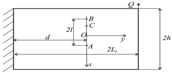
Figure 1.
Scheme of loading of the cracked beam.
We considered three possible cases of stress-strain state of the cracked beam.
Case 1. Crack with particularly contacting faces.
We assume that under external load, crack faces are smooth and enclosed in area , denoted by Point C has coordinates , where is unknown parameter, responsible for length of contact zone. The unloaded zone of the crack is denoted by
According to the problem statement, there are the following boundary conditions at the crack faces
where and are components of stress tensor; signs “+” and “−” stand for limit values of appropriate magnitude as ; is the second component of displacement vector of the beam point.
Stresses and displacements may be expressed in terms of complex potentials , according to [13]
where is shear modulus; Mushelishvili’s constant; is the first component of displacement vector of the beam point, , .
Next, we introduce complex potentials and [7,8] that describe the stress-strain state in the cantilever-uncracked strip, under the same load. For large values of they are
where
We determine the stress-strain state of cantilever-cracked strip by satisfying boundary conditions (1), (2) at the crack and by demanding that in the considerable distance from the crack potentials and have the form
Boundary conditions (1) and (2) may be rewritten as
Substitution (3) into (8) leads to the following linear conjunction problem
with the solution [13]
where
From (10) we express the function in terms of :
Next, we introduce a new function
and rewrite the boundary conditions (1) as
Using (3), (4), (11), and (12), the boundary conditions (13) are reduced to the linear conjunction problem
Solving this problem we obtain the connection
where and are unknown constants and
For large , this function allows series expansion
In order to determine coefficients and we present the function in form of power series, using formulas (5), (7), and (12). Then, taking into account (17), we equate coefficients at the same degrees of in (15). In such a way, we have
Parameter is length of the non-contacted zone of the crack. Since point lies at a greater distance from origin O than (see Figure 1), it is follows from (19) that the crack faces are in particular contact if
In such a way, we have one equation (15) in two functions
In order to obtain missing the equation, we consider the following boundary condition
Taking into account the relations (3), (11), and (12), we obtain the linear conjunction problem
Its solution is
where are unknown coefficients and
Then, the function for large values of has a series expansion
Taking into account (5), (7), (12), and (22), by expanding both sides (20) into a series at large and equating the coefficients at the same degrees of after some transformations, we obtain formulas for the unknown coefficients
Adding (20) and (15), we find the function
Function is found from (12) using (16), (21) and (24)
Stress intensity factors are determined on the base of formula [14]
Replacing the function by expression (25) in (26) we obtain
According to (18), (23), Formula (27) can be expressed as
In (28) we use the following notifications
where sign “+” corresponds to tip and “–“ to tip . In order to determine the ultimate value of force causing the crack propagation, we use the energy fracture criterion [15,16,17]
where is Young’s modulus, the effective density of surface energy of the crack for beam material.
Using (28) dependence (30) can be rewritten as
Case 2. Crack with non-contacting faces.
Now we consider the case when crack faces are not contacting. This means that the crack is completely located in the tensile zone and its faces are unloaded. In this case, must be fulfilled. The part of the axis containing the crack is denoted by On , the following boundary conditions take place
and they also may be written in form (9). Repeating the appropriate transformations we obtain dependence (11). The boundary condition (32) can be rewritten as
Taking into account (3) and (11), we come to the linear conjunction problem
Solving this problem and taking into account the behavior of function for large values of (5) we have
where
In this case, we find the stress intensity factor using Formulas (26) and (33)
where
The coefficients and are expressed by Formulas (29) at
The ultimate value of force we obtain from formula
Case 3. Crack with perfectly contacting faces.
Now we consider the case when crack faces were in perfect contact The part of the axis where the contact take place is denoted by . In this case, we have the following boundary conditions
Similarly to the previous case, we write boundary conditions at in form (6) and come to the linear conjunction problem (9). Solution of this problem has the form (11). Then, from the boundary condition
taking into account (4) and (11), we obtain another linear conjunction problem
By solving this problem, we get
Next, using Formulas (3), (11), and (12), and satisfying the boundary condition
we come to the linear conjunction problem. Its solution is given by (20).
Adding (38) and (20), we find the function
Substituting (39) into (12) gives
Considering (40) and (26), we find the stress intensity factors
where are determined according to the Formula (29).
The ultimate value of the force causing beam failure is obtained from the formula
It is known from scientific literature that the energy criteria of the fracture of cracked bodies do not always give satisfactory results. Therefore, we use an improved energy fracture criterion presented in [20].
where and are constants responsible for the fracture strength of the material and
Using (43) and (44), the ultimate force causing beam fracture for a non-contacted crack tip is determined as
and for contacted crack tip as
3. Results and Discussion
Graphical dependences of ultimate force on relative crack length at various problem parameters are presented in Figure 2, Figure 3, Figure 4, Figure 5, Figure 6, and Figure 7. Calculations were performed at . In Figure 2 and Figure 3 dependences are presented for the case of a crack with non-contacting faces.
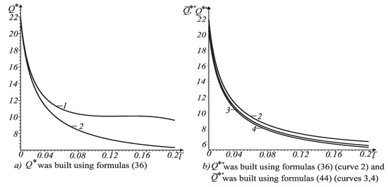
Figure 2.
Dependence of ultimate force on relative length for the crack with non-contacting faces at .
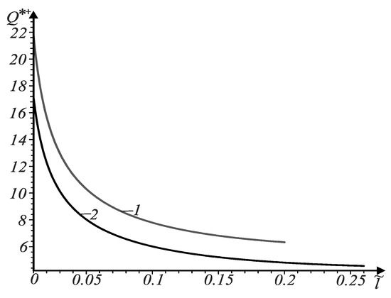
Figure 3.
Dependences of the ultimate force on the relative length for a crack with non-contacting faces at the tip at various values .
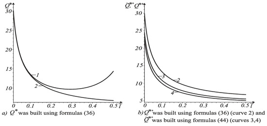
Figure 4.
Dependence of ultimate force on relative length of crack with particularly contacting faces at .
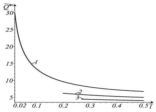
Figure 5.
Dependences of ultimate force on relative length for crack with particularly contacting faces.

Figure 6.
Dependences of the ultimate force on relative length for cracks with perfectly contacting faces at .

Figure 7.
Dependences of ultimate force on relative length for cracks with perfectly contacting faces at various values of .
In Figure 2, curve 1 corresponds to the crack tip , and curve 2 to the opposite one. These curves were built using Formula (36). Curves 3 and 4 were built using Formula (44). Curve 3 corresponds to and curve 4 – to . From analysis of these curves it follows that failure of the beam begins from crack tip where the ultimate value is lesser.
In Figure 3, curve 1 corresponds to coordinate while curve 2 corresponds to coordinate It is seen that for a fixed crack length, the ultimate force decreases with increasing distance between the crack center and the beam axis.
Dependences in Figure 4 and Figure 5 stand for cracks with particularly contacting faces at In Figure 4, curve 1 corresponds to contacting tip and curve 2 – to non-contacting crack tip . These curves were built using Formula (36). Curves 3 and 4 were built using Formula (44). Curve 3 corresponds to and curve 4 – to . It is clear that beam failure begins from a non-contacting tip.
As shown in Figure 2b and Figure 4b, the energy criterion for the fracture of cracked bodies gives an overestimated value of the force, in comparison with improved fracture criterion (42). In addition, with increasing crack length, the ultimate force decreases.
The curves in Figure 5 were constructed for non-contacting crack tip, Curve 1 corresponds to curve 2 – to curve 3 – to We can conclude that with distancing of the tip from the beam axis, the ultimate force increases.
The dependences of the ultimate force on relative length of cracks with perfectly contacting faces at various values of are presented in Figure 6 and Figure 7.
In Figure 6, curve 1 corresponds to crack tip that is closer to the beam axis, while curve 2 corresponds to remote tip . It is clear that beam failure begins simultaneously at both tips.
These curves are built for constant crack length. Curve 1 corresponds to , while curve 2 corresponds to . It follows that with distancing of the crack tip from the beam axis, the ultimate force decreases for a fixed relative length of the crack.
4. Conclusions
(1) Without regard to the location of a crack with contacting faces in the beam, expressions of stress intensity factor are the same; and of are different in all considered cases.
(2) For cracks with non-contacting or particularly contacting faces, beam failure begins distanced from the beam axis crack tip located in the tensile zone. However, in the case of perfect crack closure, this process begins closer to the tip.
(3) With increasing crack length, the ultimate force of failure of the beam decreases.
(4) For cracks with non-contacting faces, increasing the distance between the center and beam axis leads to the ultimate force decreasing, but for cracks with perfectly contacting faces, the ultimate force increases.
(5) For cracks with particularly contacting faces, the ultimate force decreases with the distance of the non-contacting tip from the beam axis.
(6) The action of concentrated force on a cantilever beam weakened by cracks with perfectly contacting faces leads to different stress-strain states, in contrast to the pure bending of the same beam with the same crack.
(7) With increasing crack length, the ultimate force always decreases.
(8) In calculating the ultimate force for cantilever beams, it is desirable to use the improved fracture criterion, without regard to location of crack and interaction between its faces.
Author Contributions
Conceptualization, M.D. and V.O.; methodology, V.O.; software, O.B.; validation, M.D., V.O. and O.B.; formal analysis, M.D.; investigation, O.B.; resources, V.O. and O.B.; data curation, V.O. and O.B.; writing—original draft preparation, M.D., V.O. and O.B.; writing—review and editing, M.D., V.O. and O.B.; visualization, O.B.; supervision, M.D.; project administration, V.O. All authors have read and agreed to the published version of the manuscript.
Conflicts of Interest
The authors declare no conflict of interest.
References
- Mosakovskyy, V.I.; Zagubizhenko, P.A. On a mixed problem of the theory of elasticity for a plane weakened by a rectilinear gap. Rep. USSR Acad. Sci. 1954, 94, 409–412. [Google Scholar]
- Mosakovskyy, V.I.; Zagubizhenko, P.A. On the compression of an elastic isotropic plane weakened by a rectilinear gap. AN SSSR OTN 1954, 88–90. [Google Scholar]
- Bojko, L.T.; Berkovych, P.E. Contact problem for a plane containing a variable width slot. J. Appl. Math. Mech. 1974, 38, 1084–1089. [Google Scholar]
- Grylitskyj, D.V.; Kit, G.S. On the stress state in the vicinity of a crack with particularly contacting edges. Mat. Methods Phys. Fields 1978, 35–39. [Google Scholar]
- Grylitskyj, D.V.; Lytsyshyn, R.M. Tension in Plates with a Circular Line of Delimitation Boundary Conditions; Vysh, Shk: Lviv, Ucraine, 1975; p. 116. [Google Scholar]
- Kryvcun, M.G.; Grylitskyj, D.V. Thermoelastic state of a plane with a heated contacting crack. Mat. Methods Phys. Fields 1981, 52–57. [Google Scholar]
- Lozovyy, B.L.; Panasjyk, V.V. Some problems of bending a strip with a rectilinear crack. AN SSSR OTN 1962, 138–143. [Google Scholar]
- Panasjyk, V.V. Vybrani Pratsi (1954–1970); NAN Ukraine. Karpenko Physico-Mechanical Institute of the National Academy of Sciences of Ukraine: Lviv, Ucraine, 2001; p. 450. [Google Scholar]
- Savruk, M.P. Two-Dimensional Elasticity Problems for Bodies with Cracks; Naukova dumka: Kyiv, Ukraine, 1981; p. 324. [Google Scholar]
- Filshtynskyy, L.A.; Hvorost, V.F. Temperature stresses in a cooling body weakened by a crack, taking into account the contact of its edges. Phys. Chem. Mater. Mech 1985, 21, 85–88. [Google Scholar]
- Bowie, O.L.; Freese, C.E. On the “overlapping” problem in crack analysis. Eng. Fract. Mech. 1976, 8, 373–379. [Google Scholar] [CrossRef]
- Guz, A.N.; Zozulya, V.V. Elastodynamic unilateral contact problems with friction for bodies with cracks. Int. Appl. Mech. 2002, 38, 895–932. [Google Scholar] [CrossRef]
- Mushelishvili, N.I. Some Basic Problems of the Mathematical Theory of Elasticity; Nauka: Moscow, Russian, 1966; p. 707. [Google Scholar]
- Savruk, M.P. Stress intensity factors in cracked bodies. In Fracture Mechanics and Strength of Materials: Reference Guide: v 4 t; Panasjyk, V.V., Ed.; Naukova dumka: Kiev, Ukraine, 1988; p. 620. [Google Scholar]
- Hui, C.Y.; Zehnder, A.T. A theory for the pasture of thin plates subjected to bending and twisting moments. Int. J. Fract. 1993, 61, 211–229. [Google Scholar] [CrossRef]
- Zehnder, A.T.; Viz, M.J. Fracture mechanics of thin plates shells under combined membrane, bending and twisting loads. Appl. Mech. Rev. 2005, 58, 37–48. [Google Scholar] [CrossRef]
- Le, K.C.; Schutte, H.; Stumpf, H. Determination of the driving force acting on a kinked crack. Arch. Appl. Mech. 1999, 69, 337–344. [Google Scholar] [CrossRef]
- Stumpf, H.; Le, K.C. Variational principles of nonlinear fracture mechanics. Acta Mech. 1990, 83, 25–37. [Google Scholar] [CrossRef]
- Stumpf, H.; Le, K.C. Variational formulation of the crack problem for an elastoplastic body at finite strain. ZAAM J. Appl. Math. Mech. 1992, 72, 387–396. [Google Scholar] [CrossRef]
- Bozhidarnyk, V.V.; Sulym, H.T. Elements of the Theory of Plasticity and Strength; Svit: Lviv, Ucraine, 1999; Volume 2, p. 418. [Google Scholar]
© 2020 by the authors. Licensee MDPI, Basel, Switzerland. This article is an open access article distributed under the terms and conditions of the Creative Commons Attribution (CC BY) license (http://creativecommons.org/licenses/by/4.0/).