Article

Conjugate Heat Transfer Analysis of PCM Suspensions in a Circular Tube under External Cooling Convection: Wall Conduction Effects

1
Department of Mechanical Engineering, National Cheng-Kung University, 1 University Road, Tainan City 701, Taiwan
2
Department of Mechanical and Energy Engineering, National Chiayi University, 300 Syuefu Rd., Chiayi City 600, Taiwan
3
Department of Civil Engineering, National Cheng-Kung University, 1 University Road, Tainan City 701, Taiwan
*
Authors to whom correspondence should be addressed.
Appl. Sci. 2020, 10(6), 2034; https://doi.org/10.3390/app10062034
Submission received: 22 January 2020 / Revised: 29 February 2020 / Accepted: 11 March 2020 / Published: 17 March 2020

Abstract

:

Featured Application

heat exchanger design; thermosiphon design.

Abstract

In this paper, a numerical method is used to investigate the conjugate heat transfer of a phase change material (PCM) suspension in a circular tube under external cooling convection. The following parameters and ranges were considered: dimensionless tube wall thickness, t w (0–0.5); wall-to-fluid thermal conductivity ratio, k w f   * (0.1–10); volumetric fraction of PCM particles, c v   (0.1); Biot number, B i o (1); Stefan number, Ste (0.1); and Peclet number, Pe (1000). The results show that the wall thermal conductivity considerably affects the outer/inner wall temperature of the tube, the average temperature of the working fluid, and the volumetric liquid fraction of PCM particles. Thus, wall conduction effects must be properly accounted for to model heat transfer in a PCM suspension in tube flow.

1. Introduction

Fine solid-liquid phase-change material (PCM) particles can be dispersed in a carrier or suspended in a working fluid to form PCM slurries or suspensions. The latent heat of absorption and release of the PCM can be used to reduce the maximum temperature and increase heat transfer in a loop. PCM particles can be prepared by microencapsulation technology [1,2,3,4,5] or emulsion technology [6,7,8]. In microencapsulation, polymer materials cover the PCM to create a barrier between the dispersed phase (PCM) and the dispersion medium (such as water and glycerol) that results in the suspension of PCM particles in the dispersion medium. The prepared PCM particles have a relatively fixed size and shape and relatively stable physical properties compared to particles prepared by other methods. However, these materials have the disadvantages of high cost, a difficult manufacturing process, reduced heat transfer efficiency from the polymer surface coating, and expansion and cracking after repeated heating. In emulsion technology, the addition of appropriate emulsifiers reduces the surface tension between the dispersed phase and the dispersion medium to produce a stable emulsion of PCM particles uniformly suspended in the dispersion medium.
Heat transfer enhancement using PCM suspensions as the working fluid has been demonstrated in forced convection. Inaba et al. [9] proposed a numerical simulation and an experiment on an isothermal outer wall. The results show that the heat transfer for a working fluid containing PCM microparticles is 1.6–2.5 times higher than that of pure water. The highest overall heat transfer is obtained for 20% PCM particles by volume. Ho et al. [10] used numerical analysis to investigate the influence of the wall thickness of a circular tube on the heat transfer characteristics of a PCM suspension. For low Peclet numbers, the forward propagation of heat along the tube wall results in the complete melting of the PCM microparticles before entrance into the heating section.
Ho et al. [11] conducted experiments on the laminar forced convection of a hybrid water-based suspension of Al2O3 nanoparticles and microencapsulated PCM (MEPCM) particles through a circular tube. The effective cooling by the hybrid suspension is significantly higher than that of the pure PCM suspension, the pure nanofluid, or water. Dammel and Stephan [12] investigated heat transfer in water-based MEPCM suspensions in laminar flow through rectangular copper mini-channels. The MEPCM suspensions perform better than water for only a certain range of parameter combinations, over which the latent heat can be exploited to a high degree.
Ho et al. [13] conducted experiments to compare the effect of substituting pure water with water-based Al2O3 nanoparticle suspensions (nanofluids) and an MEPCM suspension in the laminar forced convective cooling of an iso-flux heated circular horizontal tube. The forced convective cooling from the hybrid suspension is significantly higher than that of the pure PCM suspension, the pure nanofluid, or pure water.
Ho et al. [14] experimentally investigated the laminar forced-convection heat transfer characteristics of a circular tube heated at a constant heat flux. A phase change nanofluid (eicosane-in-water nano-PCM emulsion (particles)) was used as the working fluid under the following operating conditions: volume flow rate = 12.5–180 cm3/min, heating power applied at the outer wall of the tube = 20, 30, 40, 50, 60 W, and an inlet fluid temperature of approximately 27 °C. The results showed that when the flow rate and the heat flux are in a proper range, the tube wall temperature along the heated section can be effectively suppressed with increasing mass fraction of the nano-PCM particles in the water-based phase-change nanofluid compared with that of the pure water. Moreover, the penalty of the pressure drop increases when phase-change nanofluids are used.
Ren et al. [15] numerically investigated the impacts of the pin-fin configuration, expanded graphite (EG) content, PCM melting temperature, and heating conditions on the thermal performance of the MEPCM-EG composite with pin-fins using the three-dimensional (3D) lattice Boltzmann method. The results showed that a pin-fin array with medium fin number and fin thickness helps balance the increased heat transfer capability and the decreased latent heat of the MEPCM to achieve the optimum thermal performance.
In most of the studies in the literature, the heat transfer performance is considered to be enhanced by incorporating PCM particles. However, in these studies, the heat transfer is monitored in the heating section, and the upstream and downstream lengths from the heating section are assumed to be infinitely long. For an increase in PCM particle concentration, the corresponding increase in the cold-side heat exchange to cool the liquid PCM back into the solid state is usually neglected, along with the effect of the non-heat-exchange sections on the heat transfer of the heat exchange sections. In this context, the objective of the present study is to provide insights into the wall conduction effects on the conjugate heat transfer behavior of PCM suspensions in a circular tube under external cooling convection, for which little information is available.

2. Materials and Methods

2.1. Problem Formulation

By suitable arrangement of the heating zone and the cooling zone, the formed thermal buoyancy drives the working fluid to achieve heat transfer in the thermosiphon. The self-adjusting mechanism and stability enable extensive thermosyphon applications, such as solar heating and cooling systems, coolers for reactors in nuclear power plants, geothermal energy systems, waste heat recovery systems, and electronic cooling systems. The physical modeling of this study was inspired by the cooling section of the thermosiphon. The physical configuration of the conjugate heat transfer problem considered, as illustrated schematically in Figure 1a, is a circular pipe of inner radius r i + and wall thickness t w + (= r o + r i + ). A tube is divided into three sections: (1) an upstream adiabatic section of length L u + ; (2) a heat exchange area with a convection boundary ( T , h ) and a length of L h + , and (3) a downstream adiabatic section of length L d + . The PCM suspension enters the upstream adiabatic section at a fully developed velocity u m + , and the fluid has a uniform temperature T i n . The following basic assumptions are made in the model.
  • The working fluid is a suspension of PCM particles. The PCM particles can be completely solid phase, completely liquid phase, or a mixture of solid and liquid phases.
  • A uniform diameter is assumed for the PCM particles suspended in the working fluid.
  • All of the physical properties of the PCM suspension are assumed to be constant.
  • The PCM suspension is regarded as a thin mixture.
  • The PCM suspension is regarded as an incompressible Newtonian fluid.
  • Viscous dissipation is neglected.
  • The PCM particles are neutral and evenly distributed in the working fluid.
  • The PCM suspension enters the tube in fully developed laminar flow.
  • The flow and temperature distribution of the PCM suspension in the tube are radially axisymmetric.
  • The change in the density of the PCM particles during solid-liquid phase changes is neglected.
Based on the foregoing assumptions, the following dimensionless governing equations and boundary conditions are used in this study.
(1) Governing equation
The fluid energy equation and the tube wall heat conduction equation are as follows:
a θ F o + u 2 θ x = 1 r r ( r θ r ) + ( k b f * ρ b f * c p , b f * ) 2 1 P e 2 2 θ x 2 b c v S t e ( ξ b F o + u 2 ξ b x )
where for the fluid region (0 < r < 1), u = u + u m + = 2 ( 1 r 2 ) , a = 1, and b = ρ b f * / ρ p f * ; and for the wall region (1 r 1 + t w ), u = 0, a = ( k b f * / k p f * )( ρ w f * / ρ b f * ) ( c p , w f * / c p , b f * ), and b = 0.
The governing equation for the volumetric liquid fraction of a PCM particle ξ b is as follows:
ξ b F o + u 2 ξ b x = 12 d p 2 ( k p f * k b f * ) ( ρ b f * ρ p f * ) S t e B i p θ
A detailed treatment of the solid-liquid phase change of particles can be found in Ho et al. [10].
(2) Boundary conditions
θ = θ i n ; x = L u ,   0 r 1 θ x = 0 ; x = L u ,   1 r ( 1 + t w ) 2 θ x 2 = 0 ; x = L h + L d ,   0 r ( 1 + t w ) θ r = 0 ; r = 0 , L u x ( L h + L d ) θ r = 0 ; r = ( 1 + t w ) , L u x < 0   o r   L h < x ( L h + L d ) θ r = 1 ( 1 + t w ) B i o ( 1 + θ ) ; r = ( 1 + t w ) ,     0 < x < L h
The temperature and heat flux are assumed to be continuous at the inner wall of the tube:
θ w = θ b   and   k w f * ( θ r ) w = k b f * ( θ r ) b ; r = 1 , L u x ( L h + L d )
Thus, the mathematical formulation of the conjugate forced-convection problem consists of Equation (3), the dimensionless differential Equations (1) and (2), and the boundary conditions. The dimensionless parameters for the problem include the bulk fluid Pe; the Stefan number, Ste; the inlet dimensionless temperature, θ i n ; the dimensionless particle diameter, d p ; the volumetric fraction of PCM particles, c v ; the property ratios for the PCM particles with respect to the suspending fluid, k w f * ,   k p f * , ρ w f * ,   ρ p f * ,   c p , w f * ,   and   c p , p f * ; and the dimensionless tube wall thickness, t w . The particle Biot number, Bip and the property ratios of the bulk with respect to the fluid, k b f * , ρ b f * , and c p , b f * , which appear in the foregoing formulation, are evaluated using the relationships given in Charunkyakorn et al. [16].

2.2. Dimensionless Thermal Quantities of Interest

Several dimensionless thermal quantities of interest can be derived from the solution to the governing differential equations.
(1) Local mean temperature of the suspension fluid at a given cross section of the tube
θ b ( x ) = 0 1 u θ ( r , x ) r d r 0 1 u r d r
(2) Mean liquid-phase or melted fraction of the PCM particles at a given cross section of the tube
ξ b ( x ) = 0 1 u ξ ( r , x ) r d r 0 1 u r d r
(3) Heat transfer on the inner wall surface
The energy dissipated outward from the tube is shown in Figure 1b.
The dimensionless local heat flux at the inner tube wall can be obtained as follows:
q w , i * = q w , i k b ( T m T ) / r i + = ( θ r ) r = 1
Integrating the heat flux along the heat exchange section yields the heat transfer through the inner wall surface:
q w , i * = 1 L h + 0 L h + q w , i d x + k b ( T m T ) / r i + = 1 L h 0 L h q w , i * d x
Neglecting the axial heat conduction, the following equation can be deduced from the equation for the fluid energy:
( q w , i * ) L h , c o n v = 1 4 L h { [ θ b ( x = L h ) θ b ( x = 0 ) ] + ρ p f ρ b f c v S t e [ ξ b ( x = L h ) ξ b ( x = 0 ) ] }
where ( q w , i * ) L h , c o n v is the dimensionless total heat transfer rate to the tube wall from fluid convection heat transfer that has two components:
( q w , i * ) L h , s e n = 1 4 L h [ θ b ( x = 0 ) θ b ( x = L h ) ]
( q w , i * ) L h , l a t = 1 4 L h ρ p f ρ b f c v S t e [ ξ b ( x = 0 ) ξ b ( x = L h ) ]
The axial dimensionless heat transfer rate in the fluid is as follows:
( q w , i * ) L h , c o n d = q w , i * ( q w , i * ) L h , c o n v
(4) Heat transfer for the outer wall
The total heat transfer dissipated through the outer tube wall of the heat exchange section is as follows:
q w , o * = ( 2 π r o + ) 0 L h + h ( T w , o T ) k b ( T m T ) / r i + ( 2 π r o + ) = B i o 1 + t w k w f * k b f * ( 1 + θ ¯ w , o )
where
θ ¯ w , o = 1 L h 0 L h θ w , o d x
(5) Axial heat conduction in the tube wall
( q w * ) c o n d = 2 P e k w f * k b f * 1 t w ( 2 + t w ) [ 1 + t w 1 ( θ x ) x = 0 r d r 1 + t w 1 ( θ x ) x = L h r d r ]
(6) Nusselt number (Nu) of the inner wall surface
N u i = h i ( 2 r i + ) k b = 2 ( θ r ) r = 1 θ b θ w , i
(7) Nusselt number of the outer wall surface
N u o = U o ( 2 r i + ) k b = 2 B i o ( 1 + t w ) k w f * k b f * ( θ w , o + 1 ) θ i n + 1
where the overall heat transfer coefficient is
U o = h ( T w , o T ) ( T i n T )

2.3. Numerical Method

Spatial discretization of the differential equations was performed on a uniform mesh for the fluid and solid domains, incorporating the second-order central difference scheme for the diffusion terms and the Quadratic Upstream Interpolation for Convective Kinematics (QUICK) scheme [17] for the convective terms. Temporal derivative terms in the differential equations are treated using an implicit approximation with second-order accuracy. The algebraic discretization equations were solved through the line-by-line application of the tri-diagonal algorithm. Steady-state solutions to the governing equations were obtained numerically by a pseudo-transient approach. The temperature field was considered convergent when the maximum variation between the value computed at the present and previous iterations was less than 10−5. All computations were performed with double-precision arithmetic. Moreover, the global energy balance over the computational domain was checked for each simulation and found to always be within 0.1%.
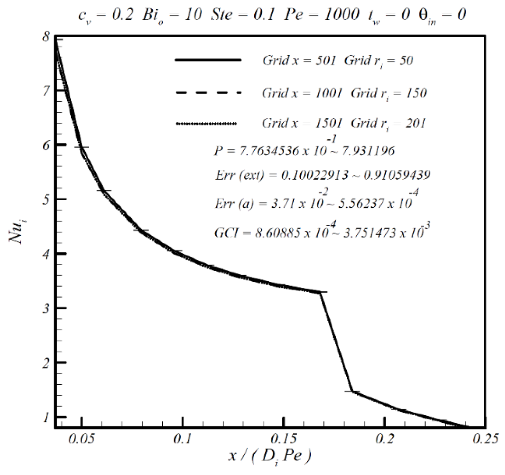
In this paper, the grid convergence index (GCI) supplemented by the extrapolated relative error is used to search for the grid point and determine the data error. The grid point test is performed for pure water and a fluid with 20% PCM particles by volume. The various errors in the local Nu of the inner and outer wall surfaces, the local heat fluxes, the average cross-sectional solid-liquid volumetric fraction, and the average cross-sectional temperature are calculated using different numbers of grid points to determine the number of grid points. Figure 2 shows one of the obtained results. For a grid point test, obtained with c v = 0 , B i o = 1 ,   P e = 1000 ,   S t e = 0.1 ,   t w = 0 ,     k w f * = 10, and θ i n = 0 , three cases have been tested, and the recommended numbers of points are 501 in the axial direction and 50 in the radial direction. For c v = 0.2 , B i o = 1 ,   P e = 1000 ,   S t e = 0.1 ,   t w = 0 ,     and   θ i n = 0 , four cases have been tested, and the recommended numbers of grid points are 2001 in the axial direction and 250 in the radial direction, which are used in this paper.
To validate the present formulation and numerical method, simulations were performed for selected cases of the forced convection of PCM suspension in a circular tube for comparison with the results that were presented in previous studies [10]. The results showed that there was no significant difference; thus, the reliability of the simulation results was confirmed.

3. Results and Discussion

Numerical results have been obtained for the parameters pertinent to the present problem in the following ranges: the dimensionless tube wall thickness, t w = 0–0.5, and the wall-to-fluid thermal conductivity ratio, k w f   * = 0.1–10. Other parameters were kept constant ( c v (0.1), B i o (1), Ste (0.1), and Pe (1000)).

3.1. Tube Wall and Fluid Temperature

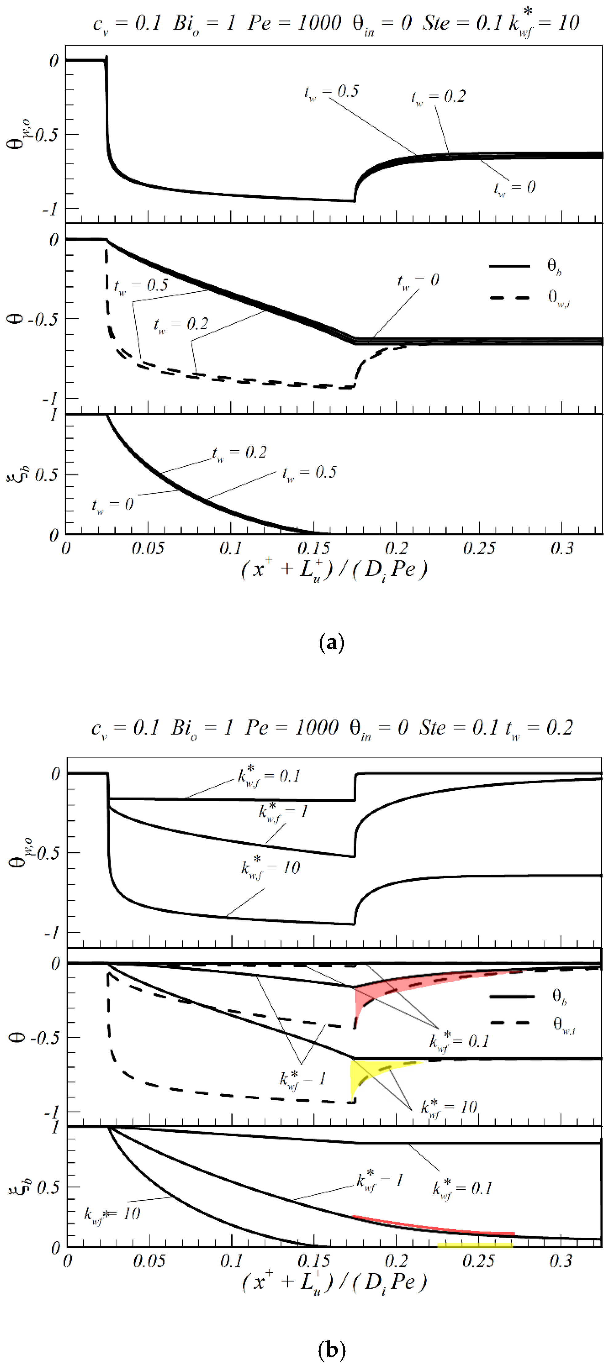
The wall conduction effect is illustrated in Figure 3 in terms of the axial distributions of the outer tube wall temperature ( θ w , o ), the inner tube wall temperature ( θ w , i ), the average fluid temperature ( θ b ), and ξ b for different values of t w and k w f * . The dimensionless distance ( x + + L u + ) / ( D i P e ) of 0 represents the starting point x + = L u + of the tube. ( x + + L u + ) / ( D i P e ) values of 0–0.025 represent the adiabatic section just prior to the cooling section. Values of 0.025–0.175 represent the cooling section. Values of 0.175 represent the adiabatic section after the cooling section. The dimensionless temperatures ( θ w , o , θ w , i , and θ b ) at the tube entrance ( ( x + + L u + ) / ( D i P e ) = 0) are set to 0. Wall conduction appears to have a strong influence on the post-cooling of the wall in the downstream regions adjacent to the cooled section. In the downstream indirectly cooled regions, the inner and outer wall temperatures increase with increases in various convex curvatures.
Figure 3a shows that there is little change in the respective temperatures and ξ b between t w = 0.2 and 0.5. Thus, t w does not directly affect the heat transfer performance of the heat exchange section. By contrast, the temperature distributions are quite sensitive to changes in k w f * . The heat transfer enhancement by the suspension fluid at fixed Ste or c v is markedly impeded by a lower k w f * , resulting in considerably higher inner and outer wall temperatures.
In Figure 3b, the post-cooling effect is increasingly discernible with increasing k w f * . For k w f * = 10, the PCM completes heat exchange when the dimensionless parameter   ( x + + L u + ) / ( D i P e ) = 0.16. The length required for the entire PCM to dissipate heat is 91% of the length of the heat exchange section. The axial propagation of conduction heat transfer along the tube wall results in an over twofold decrease in the inner and outer wall temperatures at the exit of the cooled section. The PCM suspension microparticles still undergo an exothermic reaction in the downstream adiabatic section, as shown by ξ b (the yellow line) in Figure 3. Thus, the temperature increases the fluid temperature and inner and outer walls, as reflected by the change in θ w , i , as illustrated by the yellow region.
For k w f * = 1, the reaction in the PCM suspension microparticles remains exothermic in the downstream adiabatic section, as shown by the red line for the change in ξ b   in Figure 3. Even at the terminal exit of the downstream adiabatic section, the PCM still contains unsolidified liquid, which increases the fluid temperature and thus the temperature of the inner and outer walls, as shown by the red region in Figure 3 for the change in θ w , i . Additionally, when the working fluid exits the adiabatic section, the temperatures are not yet steady (the steadiness corresponds to no further increase in the temperature). Thus, the temperature at the downstream outlet and its steadiness depend on whether the PCM latent heat is completely released in the heat exchange section.

3.2. Heat Transfer Characteristics of Inner and Outer Tube Wall Surfaces

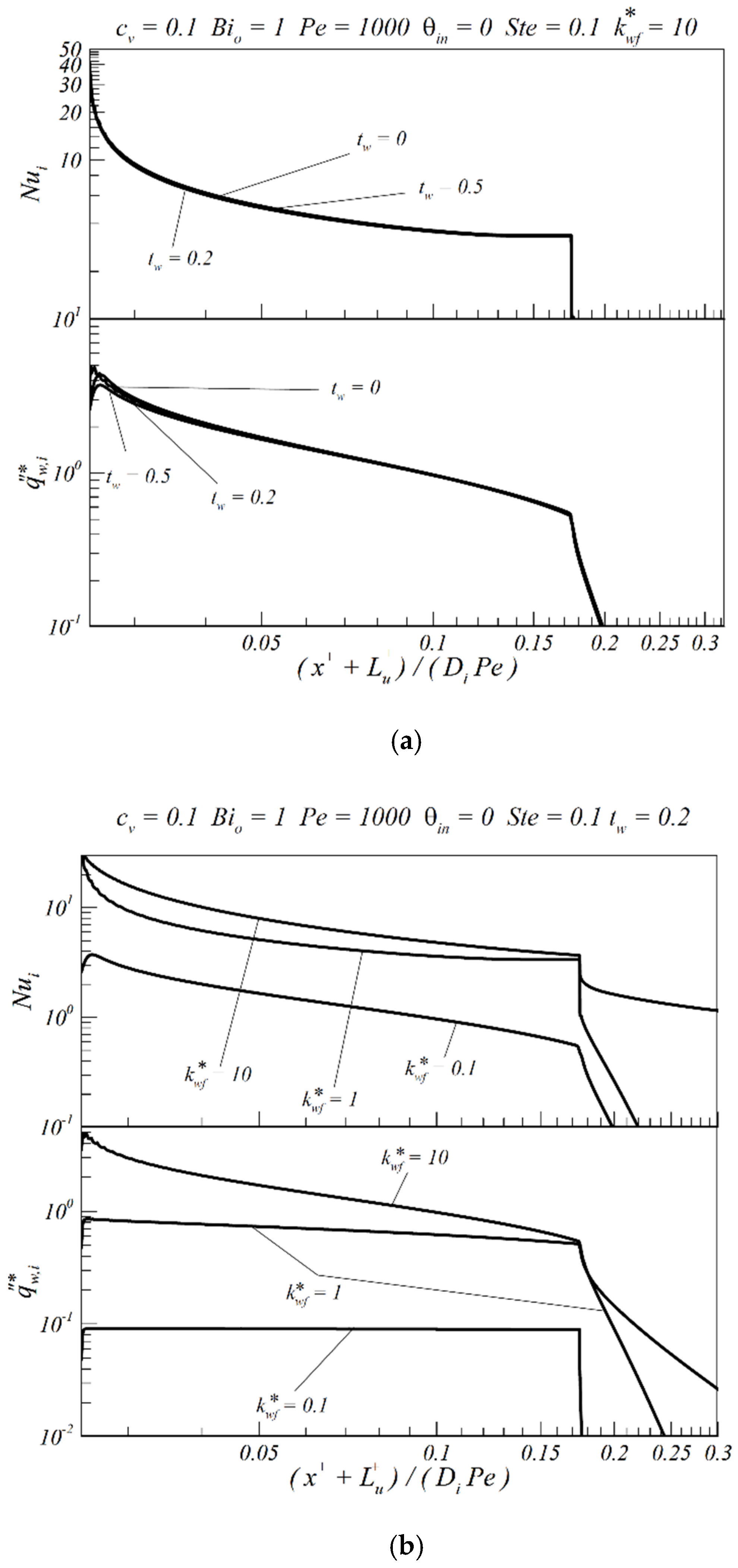
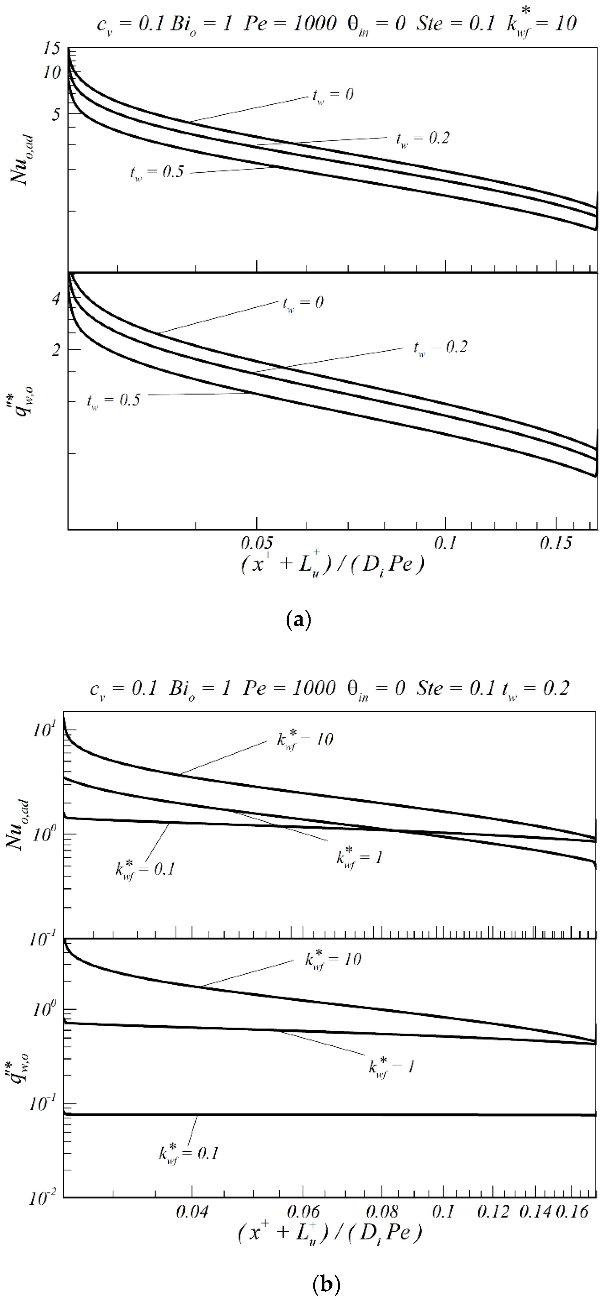
Figure 4 and Figure 5 show the local Nu and local heat flux of the inner and outer wall surfaces along the dimensionless distance ( x + + L u + ) / ( D i P e ) , respectively. The wall surface is the medium for heat exchange with the external environment. Within the considered parameter range, t w has a nonsignificant effect on the heat transfer compared to k w f * . In Figure 4a and Figure 5a, for k w f * of 10, the heat transfer and Nu are affected only by t w   at the entrance of the heat exchange region and slightly affected at the inner wall.
However, increasing k w f * markedly affects the extent of the postcooling regions. Substantial heat transfer can occur along the indirectly cooled regions of the inner and outer walls, in accordance with the foregoing postcooling effect from combined axial conduction along the tube wall and fluid stream. In Figure 4b, the post-cooling region significantly increases in size with k w f * up to k w f * = 10. For k w f * = 1, the working fluid still dissipates heat after flowing out of the heat exchange area, and the heat exchange is completely terminated only when x + + L u + D i P e = 0.24 . For k w f * = 10, the working fluid continues to dissipate heat even in the adiabatic section, confirming the significant effect of wall conduction on the heat dissipation capacity. Moreover, an iso-flux heat transfer limit along the cooled region can be increasingly achieved by decreasing k w f * , as demonstrated by the curves for k w f * = 0.1.

3.3. Analysis of Various Heat Transfer Contributions

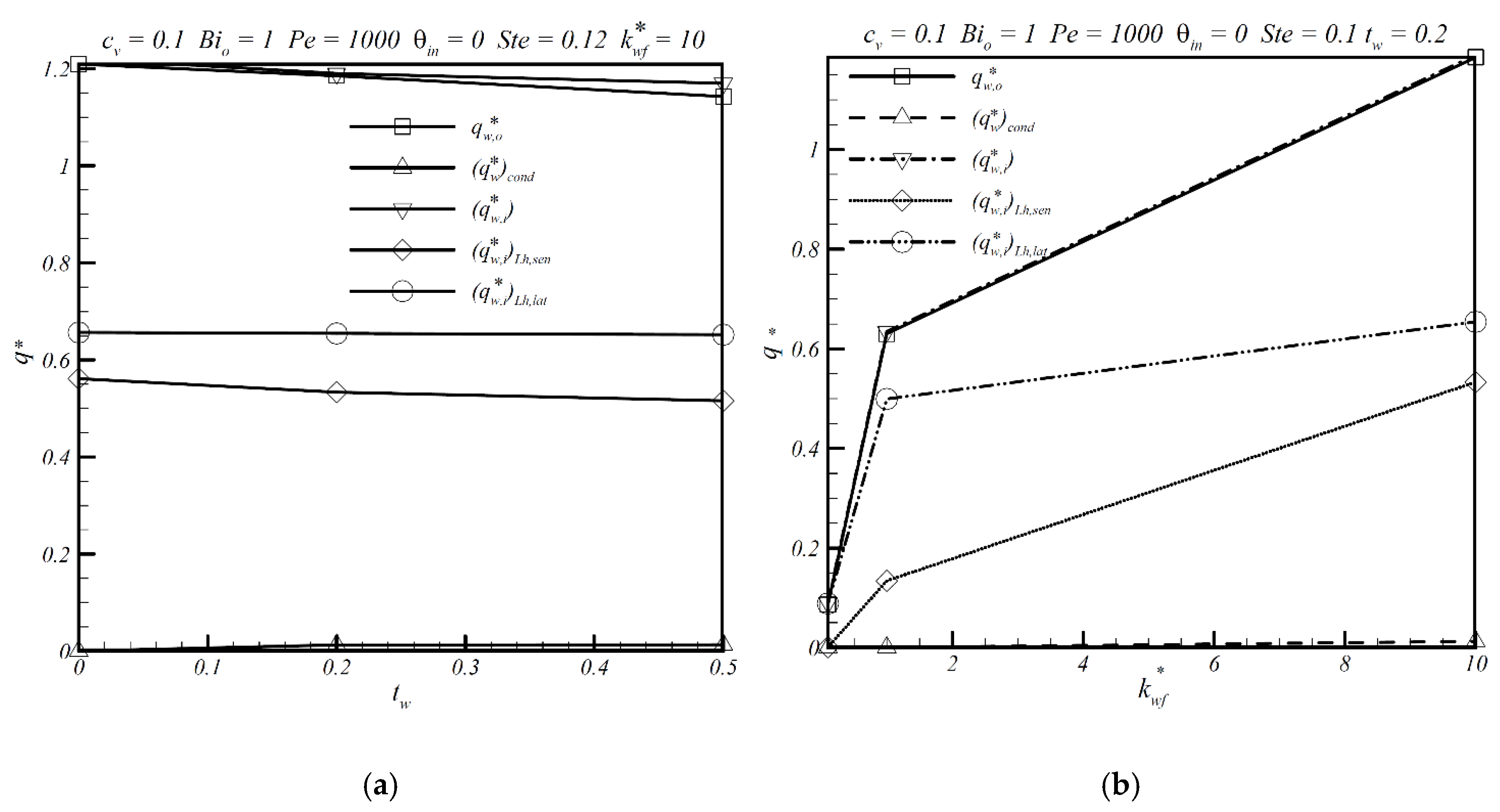
Further insight into the heat transport mechanism of the suspension fluid flowing in the tube can be gained by analyzing the following quantities: the dimensionless outer wall heat transfer ( q w , o * ), the dimensionless inner wall heat transfer over the cooled section ( ( q w , i * ) L h ), the dimensionless sensible heat transfer ( ( q w , i * ) L h ,   s e n ), the dimensionless latent heat transfer ( ( q w , i * ) L h ,   l a t ), and the dimensionless wall conduction heat transfer ( ( q w * ) c o n d ). The respective plots for these heat transfer contributions are analyzed to identify the general features of the competing mechanisms of sensible and latent heat transfer.
First, for the considered parameters, the axial fluid conduction over the cooled section accounts for approximately 0.2% of the total heat transport in tube flow (data not shown). In Figure 6a, the individual heat transfer contributions do not change significantly with t w but increase with increasing k w f * , albeit at different increments. At low k w f * values of 0.1 and 1, the latent heat transfer is the dominant mechanism for convective transport in the suspension flow, and this contribution decreases considerably as k w f * increases. For k w f * = 0.1, each of the contributions to the heat transfer rate is quite low. When k w f * = 1, the latent heat transfer ( ( q w , i * ) L h ,   l a t ) accounts for 78.67% of the inner wall heat transfer, whereas the sensible heat transfer ( ( q w , i * ) L h ,   s e n ) accounts for only 21.1% of the inner wall heat transfer; that is, most of the energy transfer is in the form of released latent heat. For k w f * = 10, the latent heat transfer ( ( q w , i * ) L h ,   l a t ) accounts for 55% of the inner wall heat transfer, and the sensible heat transfer ( ( q w , i * ) L h ,   s e n ) increases to 44.82%. This result can be explained by inspecting Figure 3b.

4. Conclusions

In this paper, numerical results have been obtained to investigate the conjugate heat transfer of a PCM suspension in a circular tube under an external cooling convection boundary. Of particular emphasis, in this study are the wall conduction effects on the heat transfer behavior. The parameters pertinent to the present problem are considered in the following ranges: the dimensionless tube wall thickness, t w = 0–0.5, and the wall-to-fluid thermal conductivity ratio, k w f   * = 0.1–10. Other parameters are kept constant ( c v (0.1), B i o (1), Ste (0.1), and Pe (1000)). The following conclusions are drawn from the results of the study.
(1)
The most significant of the considered parameters appears to be k w f * , which affects the temperature of the outer tube wall, the temperature of the inner tube wall, the average temperature of the fluid, and the volumetric liquid fraction in a PCM particle. The various contributions to the heat transfer and t w have a comparatively minor effect on the aforementioned variables.
(2)
For high k w f * , the tube wall and fluid are significantly affected by postcooling in the downstream adiabatic section. Therefore, a substantial increase in k w f * creates an indirectly cooled region downstream of the heat exchange section where the PCM particles have completed solidification. Thus, there is a significant increase in the latent heat released in the solidification process and thus the efficacy of wall temperature control over the cooled section or even the heated section.
(3)
The results of the study show that wall conduction effects must be suitably accounted for to describe heat transfer in PCM suspensions in a circular tube under external cooling convection.

Author Contributions

C.J.H. and C.-M.L. conceived of and designed the model; C.J.H. and Z.C.W. performed the simulation works; C.J.H., Z.C.W., and R.H.C. analyzed the data; and C.J.H. and C.-M.L. wrote the paper. All authors have read and agreed to the published version of the manuscript.

Funding

This research received no external funding

Conflicts of Interest

The authors declare that there are no conflicts of interest.

Nomenclature

aparameter
bparameter
BioBiot number at the outer surface of the tube (= h r o + / k w )
BipBiot number of a PCM particle (= U r p + / k p )
C p specific heat (kJ/kg K)
c p , b f * specific heat ratio (= c p , b / c p , f )
c p , p f * specific heat ratio (= c p , p / c p , f )
c p , w f * specific heat ratio (= c p , w / c p , f )
cvvolumetric fraction of PCM particles
d p dimensionless diameter of a PCM particle (= d p + / r i + )
d p + diameter of a PCM particle (m)
F o Fourier number (= α b t / ( r i + ) 2 )
hheat transfer coefficient (W/m2 K); enthalpy of suspension (kJ/kg)
h l s latent heat of fusion (J/kg)
kthermal conductivity (W/m K)
k b f * thermal conductivity ratio (= k b / k f )
k p f * thermal conductivity ratio (= k p / k f )
k w f * thermal conductivity ratio (= k w / k f )
L d + length of downstream section (m)
L d dimensionless length of the downstream section (= L d + / ( r i + P e ) )
L h + length of heated section (m)
L h dimensionless length of the heated section (= L h + / ( r i + P e ) )
L u + length of upstream section (m)
L u dimensionless length of the upstream section (= L u + / ( r i + P e ) )
PePeclet number (=2 r i + u m + / α b )
NuNusselt number (= h ( 2 r i + / k b ) )
qheat transfer rate (W)
q local heat flux (W/m2)
q * local dimensionless heat flux (= q / q o )
q * dimensionless heat transfer rate (= q / q o )
r + radial coordinate
r p + radius of a PCM particle (m)
rdimensionless coordinate (= r + / r i + )
Stemodified Stefan number (= c p , b ( T m T ) / h l s ).
ttime (sec)
t w dimensionless tube wall thickness (= t w + / r i + )
t w + tube wall thickness (= r o + - r i + ) (m)
Ttemperature (K)
udimensionless axial velocity (= u + / u m + )
u+axial velocity (m/s)
Uoverall heat transfer coefficient (W/m2 K)
xdimensionless axial coordinate (= x + / ( r i + P e ) )
x + axial coordinate
Greek symbols
α thermal diffusivity (m/s2)
θdimensionless temperature (=( T T m )/( T m T ))
ρdensity (kg/m3)
ρ b f * density ratio (= ρ b / ρ f )
ρ p f * density ratio (= ρ p / ρ f )
ρ w f * density ratio (= ρ w / ρ f )
ξvolumetric liquid fraction in a PCM particle
Subscripts
bbulk fluid
bfbulk-to-base fluid ratio
condheat conduction
convconvection
ddownstream
fsuspending fluid
hheated section
iinner surface of the tube
ininlet
lliquid phase of PCM
latlatent heat
L h heated section
mmelting point
oouter surface of the tube
pparticle
pfparticle-to-fluid ratio
sensensible heat
uupstream
wtube wall
wfwall-to-fluid ratio
ambient
Superscripts
surface-averaged quantity
*ratio of quantities
+dimensional quantity

References

  1. Ho, C.J.; Chen, Y.Z.; Tu, F.-J.; Lai, C.-M. Thermal performance of water-based suspensions of phase change nanocapsules in a natural circulation loop with a mini-channel heat sink and heat source. Appl. Therm. Eng. 2014, 64, 376–384. [Google Scholar] [CrossRef]
  2. Giro-Paloma, J.; Alkan, C.; Chimenos, J.M.; Fernández, A.I. Comparison of microencapsulated phase change materials prepared at laboratory containing the same core and different shell material. Appl. Sci. 2017, 7, 723. [Google Scholar] [CrossRef] [Green Version]
  3. Yang, L.; Liu, S.; Zheng, H. A comprehensive review of hydrodynamic mechanisms and heat transfer characteristics for microencapsulated phase change slurry (MPCS) in circular tube. Renew. Sustain. Energy Rev. 2019, 114, 109312. [Google Scholar] [CrossRef]
  4. Peng, G.; Dou, G.; Hu, Y.; Sun, Y.; Chen, Z. Phase change material (PCM) microcapsules for thermal energy storage. Adv. Polym. Tech. 2020, 3, 1–20. [Google Scholar] [CrossRef]
  5. Zhu, C.; Lin, Y.; Fang, G. Preparation and thermal properties of microencapsulated stearyl alcohol with silicon dioxide shell as thermal energy storage materials. Appl. Therm. Eng. 2020, 169, 114943. [Google Scholar] [CrossRef]
  6. Zhang, X.; Wu, J.-Y.; Niu, J. PCM-in-water emulsion for solar thermal applications: The effects of emulsifiers and emulsification conditions on thermal performance, stability and rheology characteristics. Sol. Energy Mater. Sol. Cells 2016, 147, 211–224. [Google Scholar] [CrossRef]
  7. Ho, C.J.; Hsu, H.-I.; Ho, T.-A.; Lai, C.-M. Thermal performance of a vertical U-shaped thermosyphon containing a phase-change material suspension fluid. Energies 2017, 10, 974. [Google Scholar] [CrossRef]
  8. Cabaleiro, D.; Agresti, F.; Barison, S.; Marcos, M.A.; Prado, J.I.; Rossi, S.; Bobbo, S.; Fedele, L. Development of paraffinic phase change material nanoemulsions for thermal energy storage and transport in low-temperature applications. Appl. Therm. Eng. 2019, 159, 113868. [Google Scholar] [CrossRef]
  9. Inaba, H.; Kim, M.J.; Horibe, A. Cold heat storage characteristics of latent heat microcapsule-water mixture flowing in a pipe with constant temperature wall. Trans. Jpn. Soc. Mech. Eng. B 2002, 68, 2606–2613. [Google Scholar] [CrossRef] [Green Version]
  10. Ho, C.J.; Lin, J.F.; Chiu, S.Y. Heat transfer of solid-liquid phase-change material suspensions in circular pipes: Effects of wall conduction. Numer. Heat Transf. A Appl. 2004, 45, 171–190. [Google Scholar] [CrossRef]
  11. Ho, C.J.; Huang, J.B.; Tsai, P.S.; Yang, Y.M. Water-based suspensions of Al2O3 nanoparticles and MEPCM particles on convection effectiveness in a circular tube. Int. J. Therm. Sci. 2011, 50, 736–748. [Google Scholar] [CrossRef]
  12. Dammel, F.; Stephan, P. Heat transfer to suspensions of microencapsulated phase change material flowing through minichannels. J. Heat Transf. 2012, 134, 020907. [Google Scholar] [CrossRef]
  13. Ho, C.J.; Huang, J.B.; Chen, C.P.; Tsai, P.S.; Yang, Y.M. Forced convection performance of a MEPCM suspension through an iso-flux heated circular tube: An experimental study. Heat Mass Transf. 2012, 48, 487–496. [Google Scholar] [CrossRef]
  14. Ho, C.J.; Lee, C.-Y.; Yamada, M. Experiments on laminar cooling characteristics of a phase change nanofluid flow through an iso-flux heated circular tube. Int. J. Heat Mass Tranf. 2018, 118, 1307–1315. [Google Scholar] [CrossRef]
  15. Ren, Q.; Guo, P.; Zhu, J. Thermal management of electronic devices using pin-fin based cascade microencapsulated PCM/expanded graphite composite. Int. J. Heat Mass Tranf. 2020, 149, 119199. [Google Scholar] [CrossRef]
  16. Charunyakorn, P.; Sengupta, S.; Roy, S.K. Forced convection heat transfer in microencapsulated phase change material slurries: Flow in circular ducts. Int. J. Heat Mass Transf. 1991, 34, 819–833. [Google Scholar] [CrossRef]
  17. Leonard, B.P. A stable and accurate convective modelling procedure based on quadratic upstream interpolation, Comput. Meth. Appl. Mech. Eng. 1979, 19, 59–98. [Google Scholar] [CrossRef]
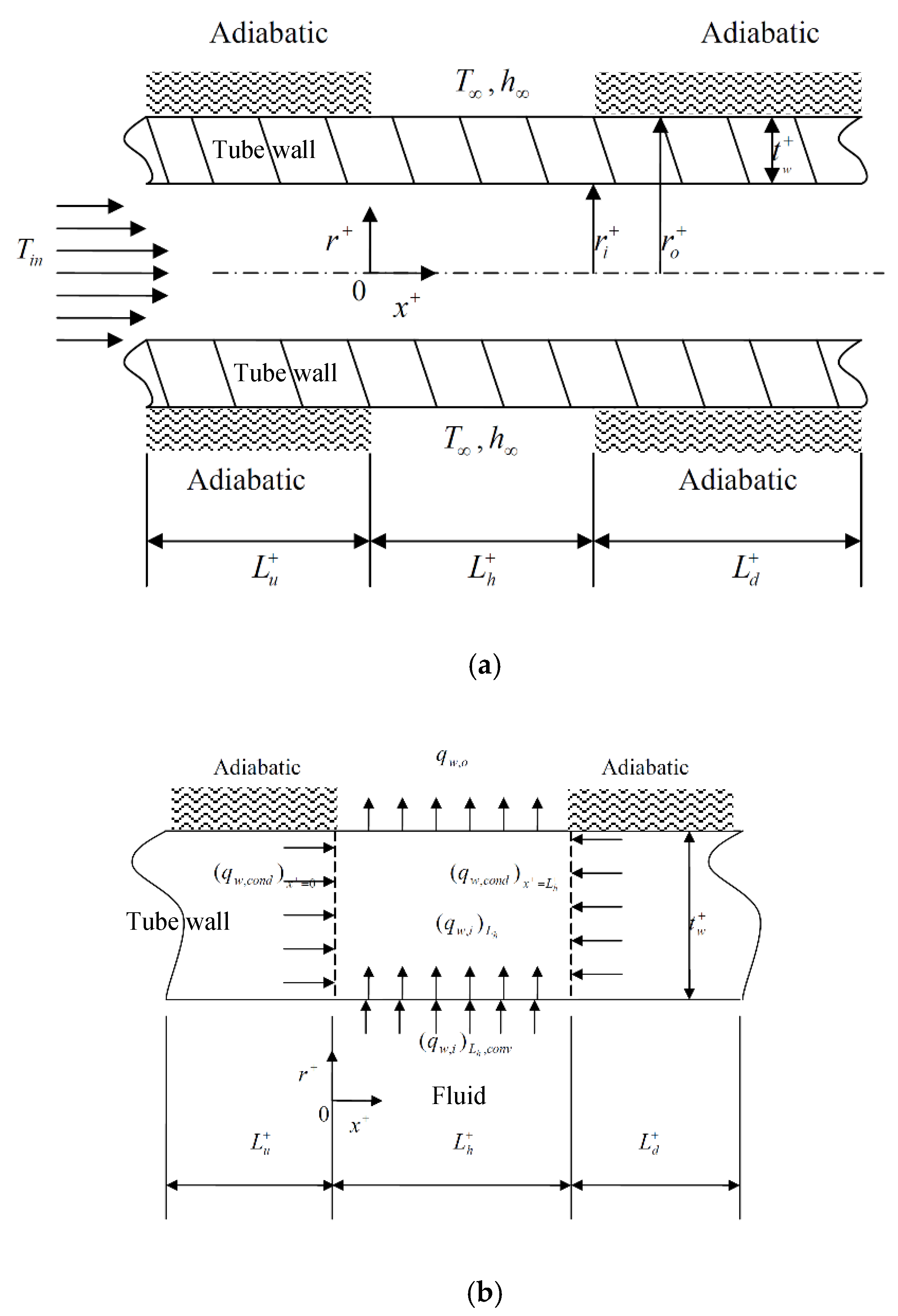
Figure 1. (a) Physical model and (b) energy dissipation processes.
Applsci 10 02034 g001
Figure 2. GCI for Nu of the inner wall and sampling value of the extrapolated relative error for different numbers of grid points.
Applsci 10 02034 g002
Figure 3. Effects of the (a) dimensionless wall thickness (tw) and (b) thermal conductivity ratio ( k w f * ) on the outer tube wall temperature (top), fluid cross section temperature (middle), inner tube wall temperature (middle), and volumetric liquid fraction in a PCM particle (bottom).
Applsci 10 02034 g003
Figure 4. Effects of (a) tw and (b) k w f * on the local Nu (top) and local heat transfer (bottom) of the inner wall.
Applsci 10 02034 g004
Figure 5. Effects of (a) tw and (b) k w f * on the local Nu (top) and local heat transfer (bottom) of the outer wall in the cooled section.
Applsci 10 02034 g005
Figure 6. Effects of (a) tw and (b) k w f * on the dimensionless outer wall heat transfer ( q w , o * ), dimensionless inner wall heat transfer over the cooled section ( ( q w , i * ) L h ), dimensionless sensible heat transfer ( ( q w , i * ) L h ,   s e n ), dimensionless latent heat transfer ( ( q w , i * ) L h ,   l a t ), and dimensionless wall conduction heat transfer ( ( q w * ) c o n d ).
Applsci 10 02034 g006