Article

Experimental Evaluation and Numerical Simulation of the Thermal Performance of a Green Roof

by
Claudia Guattari
,
Luca Evangelisti
,
Francesco Asdrubali
* and
Roberto De Lieto Vollaro
Department of Engineering, Roma TRE University, Via Vito Volterra 62, 00146 Rome, Italy
*
Author to whom correspondence should be addressed.
Appl. Sci. 2020, 10(5), 1767; https://doi.org/10.3390/app10051767
Submission received: 5 February 2020 / Revised: 25 February 2020 / Accepted: 28 February 2020 / Published: 4 March 2020
(This article belongs to the Special Issue Building Physics and Building Energy Systems)

Abstract

:
In the building sector, both passive and active systems are essential for achieving a high-energy performance. Considering passive solutions, green roofs represent a sustainable answer, allowing buildings to reach energy savings, and also reducing the collateral effect of the Urban Heat Island (UHI) phenomenon. In this study, a roof-lawn system was investigated by means of an extended measurement campaign, monitoring the heat transfer across the roof. Heat-flow meters and air- and surface-temperature probes were applied in a real building, in order to compare the performance of the roof-lawn system with a conventional roof. This experimental approach was followed to quantify the different thermal behaviors of the building components. Moreover, an equivalent thermal model of the roof-lawn system was studied, in order to obtain the equivalent thermal properties of the roof, useful for setting building models for yearly energy simulations. The roof-lawn system revealed its advantages, showing a higher thermal inertia with no overheating in summertime and a lower thermal transmittance with energy savings in wintertime, and, consequently, better indoor conditions for the occupants of the building.

1. Introduction

In recent years, urban areas’ growth and the consequent sources of pollution have led to an increase in terms of global warming. In addition, the so-called Urban Heat Island (UHI) phenomenon has developed. UHI is represented by the temperature rises in areas characterized by a high urban fabric, if associated to the surrounding rural areas [1]. The evaluation of the UHI phenomenon is crucial to design plants effectively and to evaluate the buildings’ energy needs. It is noteworthy to suggest interventions for the mitigation of this phenomenon, lowering its intensity. Achieving this goal is fundamental to reducing the increasing building energy consumption, especially during the warmer months [2,3]. If, on the one hand, the internal temperatures of the buildings can be set lower, the same cannot be done for the external environment, with the exception of countermeasures finalized for the reduction in UHI effects. Furthermore, the high temperatures that occur in cities during the warmer months can involve substantial and damaging effects on daily life [4,5,6,7].
Therefore, the UHI phenomenon and its countermeasures are topics of interest in the scientific literature. Several works aimed at assessing UHI intensity suggest strategies to reduce its impacts, such as building design approaches [8,9,10]. Several mitigation measures were recommended in order to mitigate UHI impacts on environmental, energy, economic and social aspects. Some of them are based on the existing correlation between the UHI and the polluting gases in the atmosphere. Consequently, the reduction in pollutant emissions has a direct influence on the UHI, and the UHI reduction has a direct influence on building energy consumption [11,12]. All this can be achieved by means of a rational buildings project, but also considering the emissions reduction induced by transport or industrial sources. Further mitigation solutions can be reached by employing construction materials with a high albedo.
This research focused on the assessment of the effectiveness of a green roof thermal behavior. The goal was to analyze the thermophysical properties and thermal behavior to estimate the real effect on the building’s energy performance optimization.
Several measuring instruments were installed for observing heat transfer phenomena across the green roof. The experimental campaign consisted of acquiring data from both the green roof and a nearby conventional roof, in order to compare the thermal performance.
Moreover, the roof-lawn system, characterized by a multilayer structure, was reproduced using a Finite Element Model (FEM) code for obtaining equivalent thermophysical properties. It is worthy to mention that the compositions of the roofs were known but the thermophysical properties of each layer were undetermined. In addition, the green roof is made of five layers, of which the roof-lawn is non-homogeneous, and consists of a layer of grass and the underlying substrate. On the other hand, the original roof is made by only three layers (explained in the following section), characterized by conventional materials. This approach was applied for achieving suitable information for creating building energy models for the simulation of yearly energy needs.
The roof-lawn system showed its advantages, pointing out a higher thermal inertia with no overheating during the warmer months and a lower thermal transmittance. This resulted in lower energy demands and, consequently, better internal environmental conditions.
Consequently, it is possible to assert that a green roof can enhance the thermal inertia of a roof, thus increasing the internal comfort, reducing energy needs [13,14,15,16,17,18,19]. In addition, if installed in high-density urban areas, a green roof can offer positive contribution against the UHI phenomenon, also absorbing polluting gases.
The novelty of this work is related to two different aspects: on one hand, a yearly monitoring of a green roof can be useful for readers, showing the thermal behavior of a roof-lawn resting on an existing roof. This is a long first analysis of a deeper optimization study of the structural part of the roof, aimed at designing a stratigraphy better able to work with the overlying roof-lawn. On the other hand, an inverse method was applied here to evaluate the equivalent thermophysical properties of a green roof inside an innovative methodological approach.

2. Materials and Methods

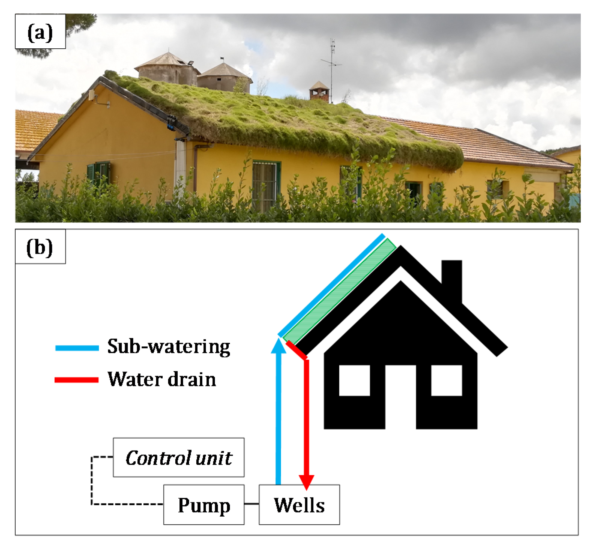
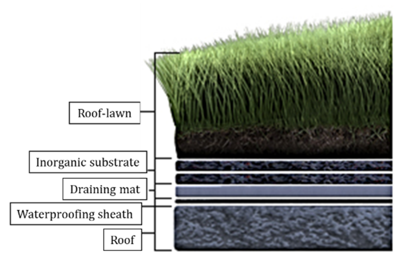
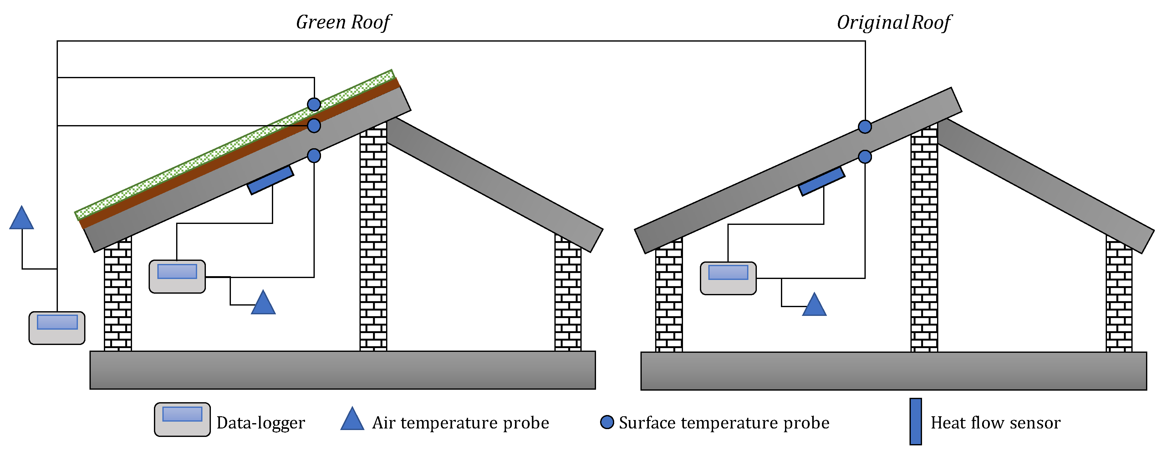
2.1. On-Site Measurements
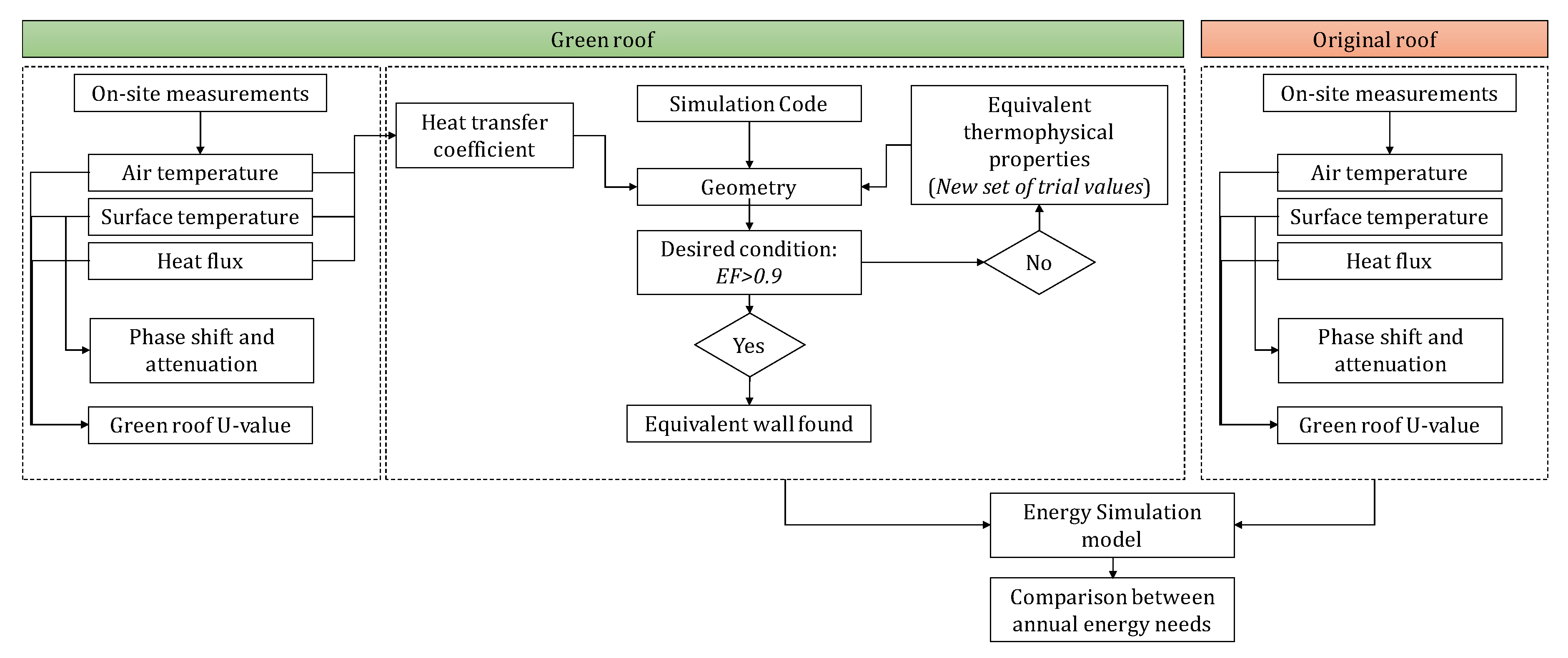
The experimental survey was done by analyzing a roof-lawn system installed on the roof of a single-story building (see Figure 1a) situated in the countryside near the city of Latina (about 70 km south of Rome). This research aimed at evaluating the thermal characteristics of a green roof by means of an extended measurement campaign. The roof-lawn system is an innovative patent, characterized by the species of the Zoysia genus (distinguished by a slow growth and a typical wave effect). The realization of the water system only reintegrates the losses due to evapotranspiration. The level of maintenance required for the green roof is extremely low, since the routine maintenance is not required. Once it reached the maximum growth, the vegetation has a characteristic wave effect with average foliage heights that do not exceed 25 cm. The whole system components are reported in Figure 1b.
The stratigraphy of the roof is shown in Figure 2. The green roof is characterized by different layers: on the upper part of the roof, a waterproofing sheath was installed to avoid water infiltration; over that, the green roof was built on a draining mat and an inorganic substrate. The structural part of the roof is composed of a reinforced concrete layer, with a thickness of about 8 cm. The overall thickness of the green roof is equal to 20 cm.
Only a half of the building roof is characterized by the installation of the roof-lawn system, while the other half remained in the previous condition. The original roof is made of a reinforced concrete slab with a thickness of about 8 cm, covered with tiles. A waterproof membrane is installed on the concrete slab. The two rooms under the roofs are characterized by the same orientation and the same occupation rate.
To assess the behavior of the green roof and define the characteristics of the system in terms of stationary and dynamic thermal performance, heat flow sensors, air temperatures probes and surface temperature sensors were installed, as shown in Figure 3. The measuring instruments’ technical data are reported in Table 1.
It is worth mentioning that the external surface temperature probe installed on the upper layer of the green roof was inserted below a first small layer of soil, in order to guarantee the best thermal contact. The schematic representation reported in Figure 3 could be misleading, as it represents the external surface temperature probe (blue circle) on the outermost part of the green layer. Of course, the upper part of a green roof is made of grass and surface temperatures cannot be measured. Therefore, the surface temperature probe was installed, placing the sensor in the upper part of the soil, where the grass grows.
All sensors were connected to the data-loggers, recording heat fluxes, air and surface temperatures with a timestep equal to 10 min, for 24 h per day. The measurement campaign started in October 2018 and finished after one year, in September 2019. All the acquired data were used to calculate the thermal transmittances (also known as U-value or merely U) of the green roof and the original roof.
Heat fluxes and air temperatures can be used for calculating the U-value by applying the following formula
q = U ( T i T e )
where q is the heat flux density, and Ti and Te are the air temperature in the internal and external environment, respectively. According to the standard ISO 9869-1 [21], heat fluxes and air temperature values were used for calculating the stationary U-value of the roof by applying the average progressive method, following the formula
U = j = 1 N q j j = 1 N ( T i j T e j )
where N is the total registered samples.
In addition, using surface temperatures instead of air temperatures, the thermal conductance (C-value or only C) of the roof can be deduced, by applying the following equation
C = j = 1 N q j j = 1 N ( T s i j T s e j )
where Tsi and Tse are the internal and external surface temperatures, respectively.
Moreover, internal and external surface temperatures were also used to obtain information about the dynamic thermal performance of the roofs, in terms of heat waves’ phase shift and decrement factor.
The heat waves’ Phase Shift (PS) can be evaluated as the time difference between the maximum value of the internal surface temperature and the maximum value of the external surface temperature of the roof [22]
P S = t T s i M A X t T s e M A X
The Decrement Factor (DF) can be defined as follows [22]
D F = T s i M A X T s i M I N T s e M A X T s e M I N
where T s i M A X   and T s i M I N are the maximum and the minimum internal surface temperatures registered in a day, and, in turn, T s e M A X   and T s e M I N are the maximum and the minimum surface external temperatures registered in a day.

2.2. Methodology

In order to assess the thermal behavior of the green roof and its effectiveness in terms of energy savings, it was necessary to analyze and compare the thermal performance of the two parts of the roof. It is worth to mentioning that the stratigraphies of the two roofs were known but the thermophysical properties of each layer were undetermined. In addition, the green roof is made of five layers, of which the roof-lawn is non-homogeneous, and it consists of a layer of grass and the underlying soil. On the other hand, the original roof is made of only three layers, characterized by conventional materials. For this reason, data obtained from the on-site measurement campaign were used for generating a model through Comsol Multyphysics software [23,24]. The experimental system registered data useful in setting the boundary conditions in the model. Taking into account the direction of the heat flux caused by the difference in temperature between the two sides of the roof, a thermal input, equal to the experimental surface temperature trend, was set. The internal measured air temperatures and the heat fluxes were employed to calculate proper internal heat transfer coefficients.
The stratigraphy of the actual green roof was reproduced in Comsol as a single homogeneous layer, characterized by equivalent thermophysical properties, following the method demonstrated in [25]. Simulations were performed in different periods of the year, all characterized by no thermal inversion between internal and external air temperatures and heat fluxes characterized by the same direction for a better calculation of the internal heat transfer coefficients (hint) [26].
On-site measurements were used as boundary conditions in the model: external surface temperature values were used as an external forcing function; on the other side of the equivalent layer, a heat transfer based on the equation q = h i n t ( T T e n v ) was set, where T is the internal surface temperature and Tenv is the temperature of the environment, outside the simulated domain (in this case corresponding to the indoor air temperature). From experimental measurements, hint values along time were calculated and used in the simulation code. Thus, different equivalent thermophysical properties were iteratively tested and the internal surface temperatures were simulated. The search for equivalent thermophysical properties aimed to obtain the best reproduction of the behavior of the green roof, to obtain the best correspondence between the measured and simulated internal temperatures of the surface. The desired condition to stop searching for the best parameters is represented by a Model Efficiency (EF) value greater than 0.9 [23], expressed as
E F = i = 1 N ( m i m ¯ ) 2 i = 1 N ( s i m i ) 2 i = 1 N ( m i m ¯ ) 2
where mi is the measured value at time ti, si is the simulated value for each time ti, m ¯ is the average of the measured values and N is the total number of samples. EF can understand the capability of the equivalent structure to reproduce the original one’s behavior, showing values between 0 and 1 (which indicates that measured and simulated data are equal).
Finally, the thermophysical properties obtained by the green and the original roofs were used in the energy simulation software TRNSYS in order to obtain the annual energy needs of a detached building. Thus, the comparison between the energy demands allowed the evaluation of the advantages deriving from the installation of a green roof. Considering that the solar reflectance of green roofs varies between 0.3 and 0.5 depending on the plant types [27], here, a reflectivity of 0.3 (typical value for leaves) was used in the model. The detached building was modelled considering walls consisting of a 0.22 m layer of concrete and a 0.04 m XPS layer, plastered on both sides, with a U-value of 0.600 W/(m2K). The windows (U-value of 5.61 W/(m2K)) are characterized by a total area equal to 18 m2. The walls’ solar absorptance coefficient was set equal to 0.6. The infiltration rate was set at 0.3 1/h and the indoor set-point temperatures for heating and cooling were set as equal to 20 and 26 °C, respectively. The flow-chart of the applied methodological approach is reported in Figure 4.

3. Results and Discussion

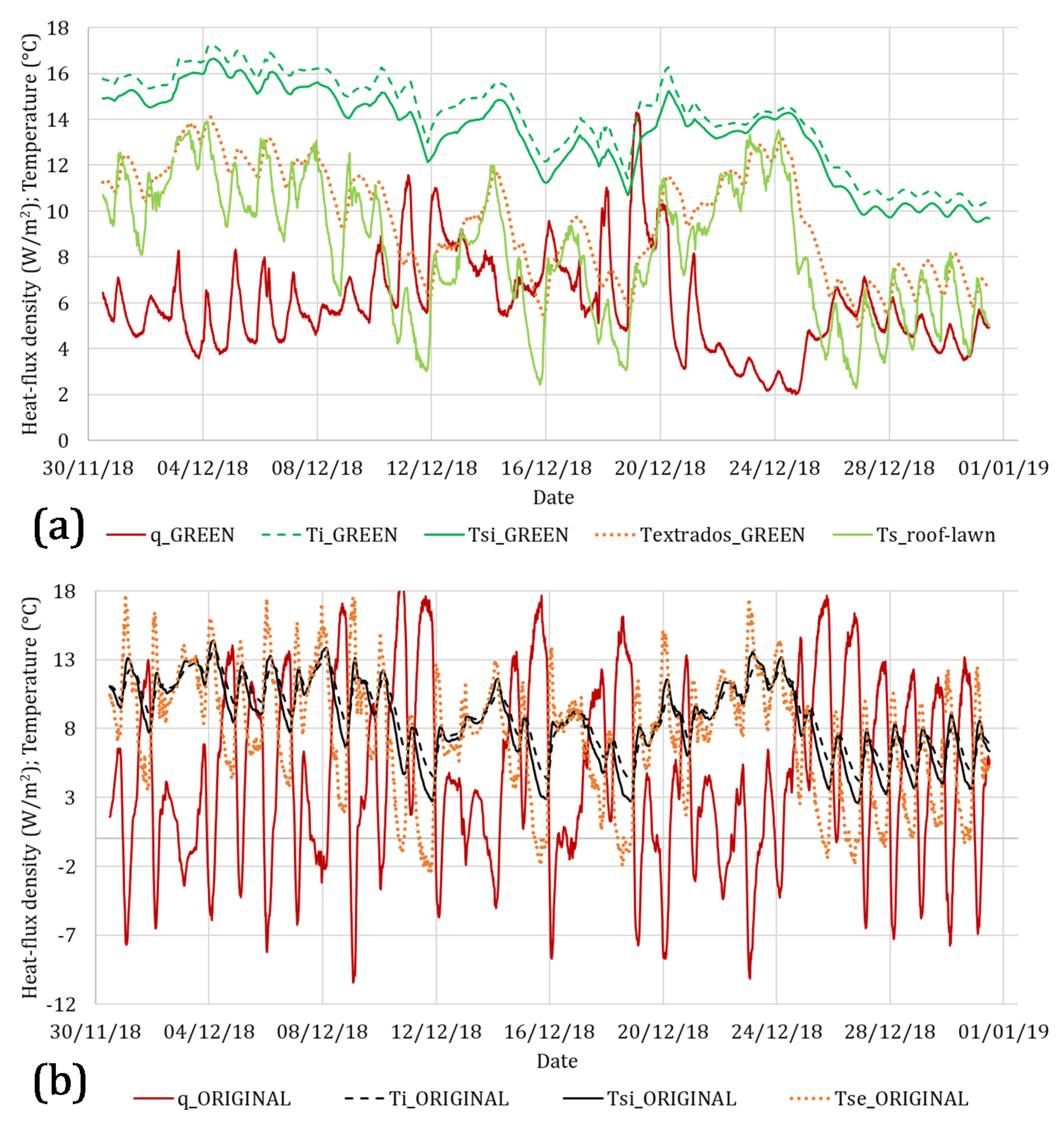
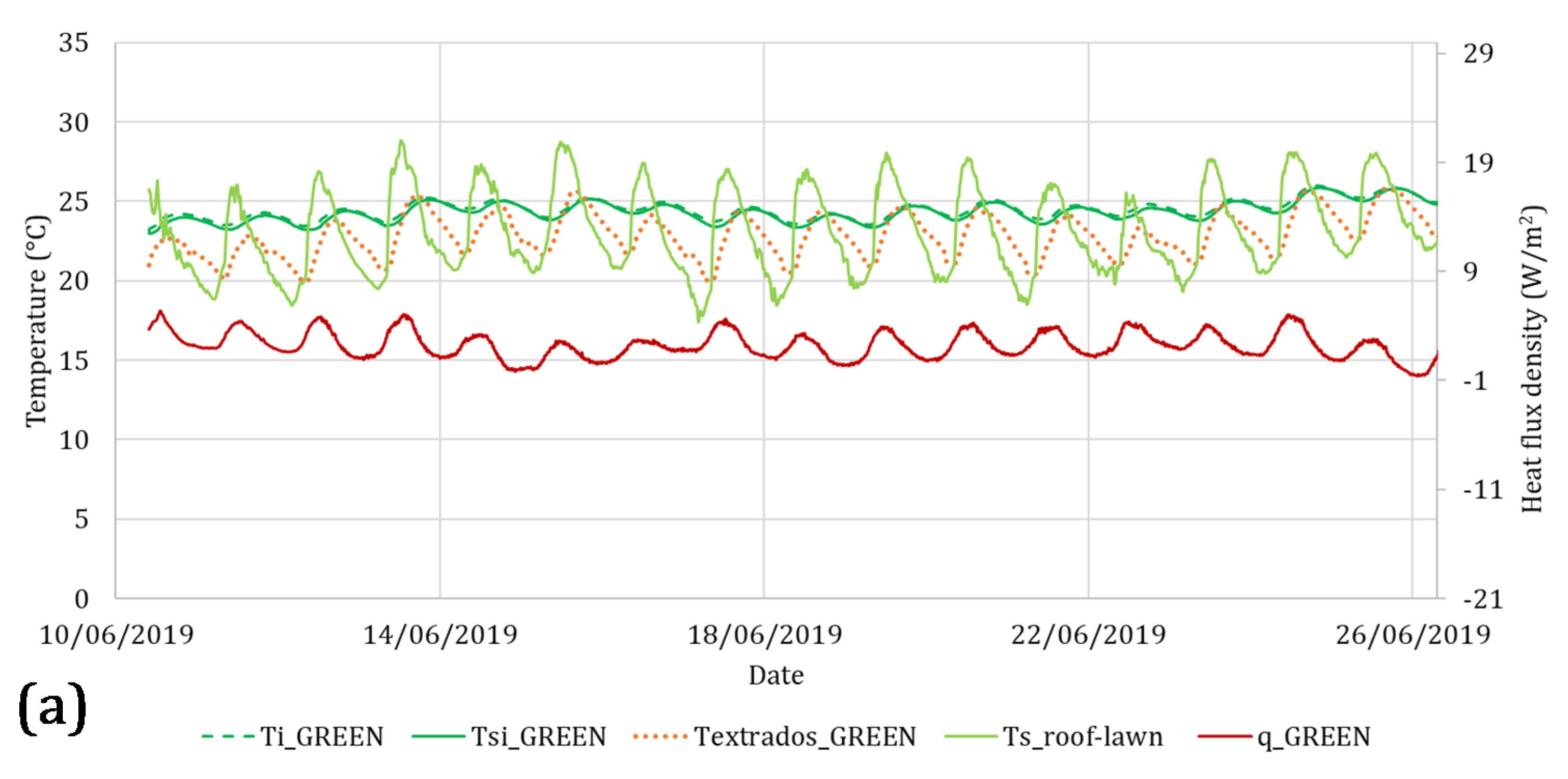
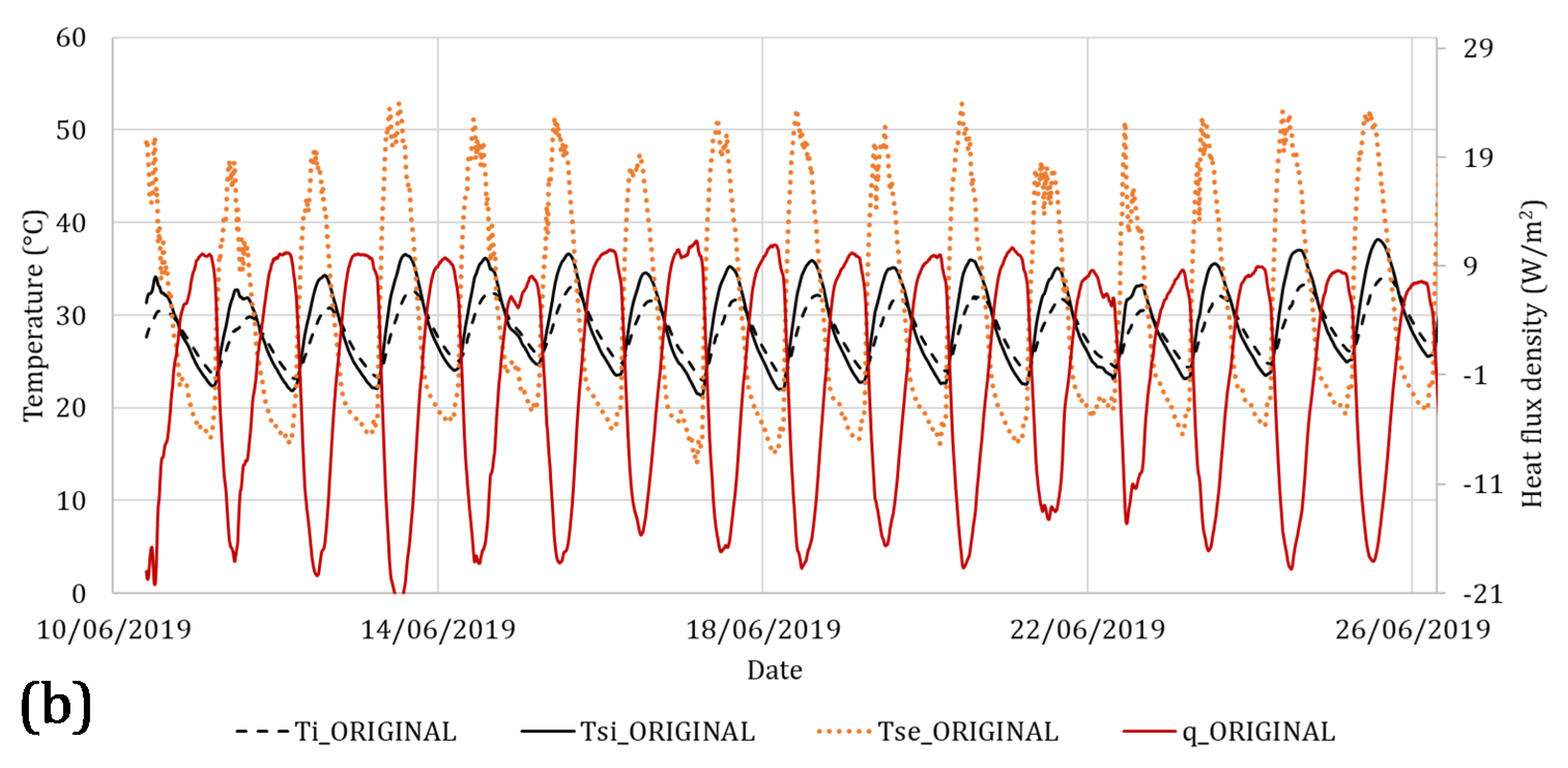
3.1. Experimental Investigation

The results obtained during the measurement campaign are reported in this section. The monitoring was conducted from October 2018 to September 2019. The results of one year of measurements are a wealth of collected data. For the sake of brevity, partial data referring to winter and summer are presented here. This approach can be useful for readers to understand the thermal behavior of the green roof under different climatic conditions.
Regarding the winter season, the time range chosen to be analyzed was from 1st of December to 31st of December. This period was selected due to the low temperatures recorded. During this month the outdoor temperature range was between 3.83 and 14.16 °C.
The data registered during this period are reported in Figure 5, where Figure 5a refers to the green roof and Figure 5b to the traditional roof (distinguished in the label as “ORIGINAL”). In Figure 5a, the heat flux (called q_GREEN) is represented by the continuous red line, the indoor air temperature (called Ti_GREEN) is represented by the dashed green line and the internal surface temperature (called Tsi_GREEN) is represented by the continuous green line. On the other side of the roof, the surface temperature registered under the green roof was called Textrados_GREEN (orange dotted line) and the temperature of the upper layer of the green roof (measured inserting the sensor below a first small layer of soil) was called Ts_roof-lawn (continuous line of light green color).
On the other hand, in Figure 5b, the heat flux (called q_ORIGINAL) is depicted by the continuous red line, the indoor air temperature (called Ti_ORIGINAL) is represented by the dashed black line and the internal surface temperature (called Tsi_ORIGINAL) is depicted by the continuous black line. On the other side of the roof, the external surface temperature was called Tse_ORIGINAL and it is represented by the orange dotted line.
Observing both heat fluxes and temperatures, it is possible to notice a more stable thermal behavior of the green roof if compared with the original one. Referring to the green roof, analyzing the indoor temperatures and the internal surface temperatures, it is possible to obtain average values equal to 14.14 and 13.39 °C, respectively. On the contrary, for the original roof, an average indoor temperature of 8.95 °C and an average internal surface temperature of 8.58 °C can be observed. In order to provide a straightforward comparison among the acquired heat fluxes and temperatures, the upper limit of the ordinate axes was limited to the same value. Considering the green roof, the highest value for the heat flux was equal to about 14 W/m2, a much lower value than those registered for the original roof. The different inertial behavior of the original roof allowed the observation of a strong fluctuation of heat flows, also showing negative values. Taking into account the external surface temperatures, it is possible to notice that the original roof is characterized by higher values. The main reason to explain these results is strictly related to the thermophysical characteristics of the employed materials. The roof covering tiles have a high solar radiation absorption coefficient, unlike green roofs, which are characterized by evapotranspiration phenomena.
The registered data allowed us to calculate the steady-state thermal transmittance of the roofs. Applying Equation (2), the U-values shown in Figure 6 were computed; it can be noticed that, after a few days, both thermal transmittances tend to reach a stationary value. A thermal transmittance of 1.361 W/(m2K) was obtained for the green roof. On the other hand, a value of 3.021 W/(m2K) was found for the original roof. Therefore, comparing the green and the original roofs U-values, a percentage difference of about −55% can be highlighted.
Regarding the middle season, the time range chosen to be analyzed was from 10th of June to 26th of June. During this period, the outdoor temperatures range was between 5.53 and 26.23 °C. The heat fluxes, indoor temperatures and internal surface temperatures recorded during middle season are reported in Figure 7, where Figure 7a refers to the green roof and Figure 7b to the original roof. The graphical representation of heat fluxes and temperatures is the same as that used in Figure 5. In order to provide a straightforward comparison among the acquired heat fluxes, the upper and lower limits of the secondary axes are the same. Even if the average indoor temperatures and the average internal surface temperatures are not significantly different between the two roof configurations, during this period it is possible to notice a more stable thermal behavior of the green roof. As a matter of fact, it is possible to notice that the heat fluxes along time of the original roof show much higher fluctuations than those observed for the green roof (the heat flux of the original roof ranged between −32.56 and 19.04 W/m2). Due to the thermophysical properties of the material used for the roof, in this case the external surface temperatures showed different values. The external surface temperatures of the original roof reached values above 40 °C, while the external temperatures of the roof-lawn system reached values below 22 °C.
Regarding the summer season, the time range chosen to be analyzed was from 10th of June to 26th of June. This period was selected due to the high temperatures recorded. During this period, the outdoor temperatures range was between 16.0 and 33.4 °C.
The heat fluxes, indoor temperatures and internal surface temperatures recorded during summer are reported in Figure 8, where Figure 8a refers to the green roof and Figure 8b to the original roof. In this case, the graphical representation of heat fluxes and temperatures is the same as that used in Figure 5. In order to provide a straightforward comparison among the registered heat fluxes, the upper and lower limits of the secondary axes are the same. It is possible to observe a more stable thermal behavior of the green roof also during summertime. Considering the green roof, the average indoor temperatures and the average internal surface temperatures are equal to 24.80 and 24.60 °C, respectively.
On the contrary, for the original roof, an average indoor temperature of 28.93 °C and an average internal surface temperature of 29.87 °C can be noticed. Regarding the heat fluxes, in the green roof a mean value of 2.19 W/m2 was registered. On the contrary, in the original roof, a negative mean value of −1.86 W/m2 highlighted the incoming direction of the heat flows. Analyzing the external surfaces’ temperatures, the original roof reached 50 °C, while the external temperatures of the roof-lawn system reached values below 30 °C. As mentioned before, the influence of the thermophysical characteristics of the materials used played a fundamental role. The solar radiation was absorbed by the original roof covering tiles due to their high absorptance coefficient. This did not happen for the green roof, characterized by evapotranspiration phenomena.
As previously mentioned, the dynamic performance of the roofs can be evaluated by means of the heat waves’ phase shift. PS and DF parameters were obtained analyzing the summer months, when the solar radiation provides the highest influence. The average PS of the green roof was equal to 6 h and 50 min, much higher than the original roof, with a PS of 3 h and 30 min. In terms of decrement factor, the green roof showed a DF equal to 0.19, while the original roof was characterized by a DF equal to 0.37. It is essential to have a thermal wave phase shift of at least 8 h, or of no less than 10 h in areas characterized by a hot summer. The phase shift value, often neglected during the design phase, is surely critical for determining summer thermal comfort, with effects in terms of energy savings. In summer, the heat stored by the envelope is gradually released inside the rooms with a time delay that attenuates and postpones the heat peak, thus reducing the cooling energy needs. Here, the roof-lawn system is simply placed on a reinforced concrete slab which was not optimized to obtain the best performance of the roof. For this reason, future developments will concern the optimization of the structural part of the roof, designing a stratigraphy able to work with the overlying roof-lawn.

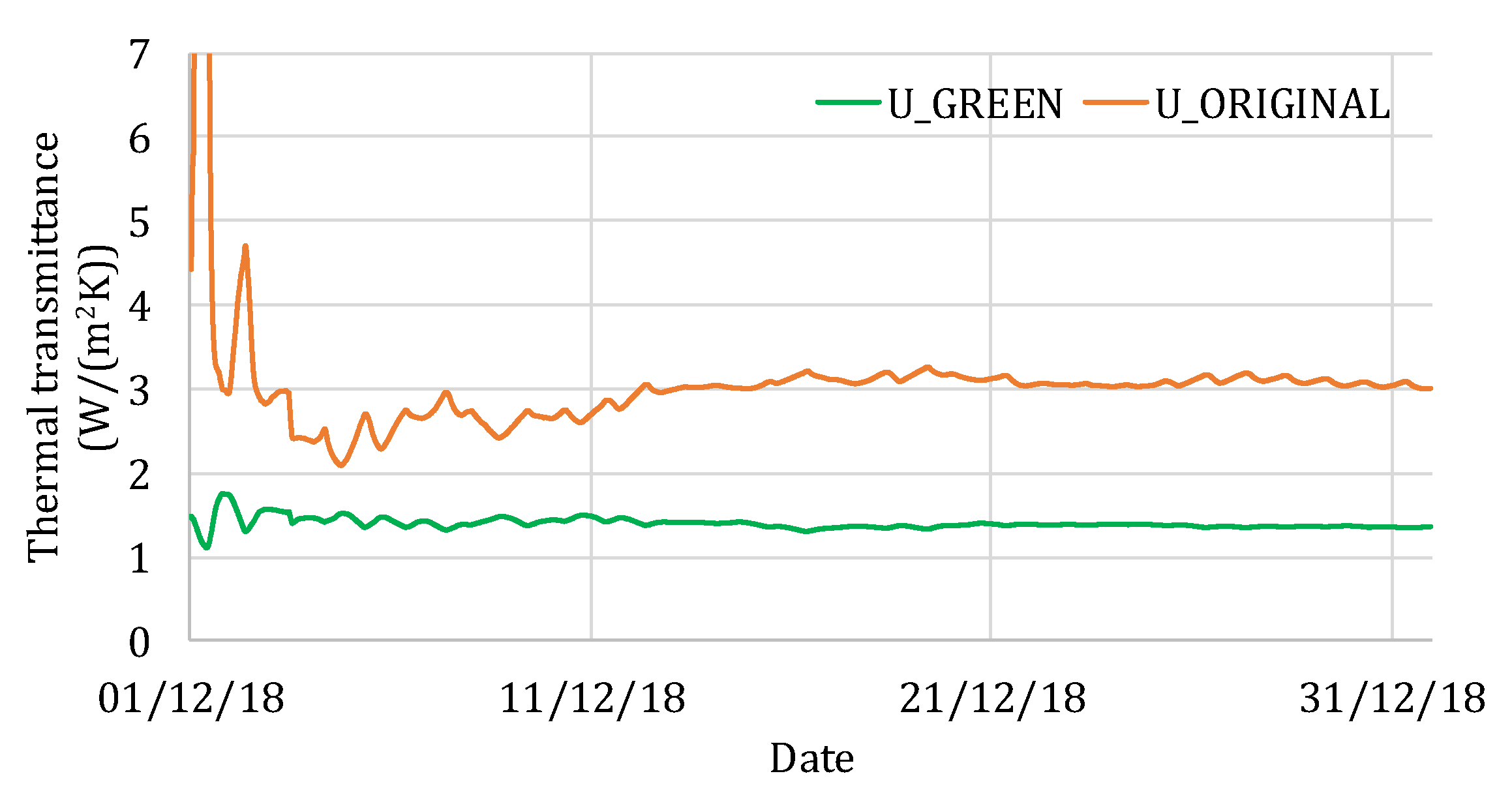
3.2. Equivalent Thermophysical Properties

On-site measurement data were used for generating a model through Comsol software. Thus, different equivalent thermophysical properties were iteratively tested and the internal surface temperatures were simulated. The search for equivalent thermophysical properties aimed at finding the best reproduction of the green roof behavior, trying to get the best match between internal measured and simulated surface temperatures. The best matching is shown in Figure 9a, where the comparison between measured (green line) and simulated (black dotted line) internal surface temperatures is reported.
During summer, the overlap between experimental and simulated data was found, setting the following equivalent parameters: thermal conductivity equal to 0.4 W/(mK), specific heat capacity equal to 840 J/kgK and mass density equal to 1100 kg/m3. The equivalent thermophysical properties mentioned before were also tested during middle season (April) and winter (December), when the external climatic conditions are different (see Figure 9b,c). The EF coefficients were calculated in all the mentioned seasons: during summer, EF = 0.96 was obtained; during the middle season, EF = 0.96 was computed; and, finally, during winter, EF = 0.93 was found.
The EF values are all higher than 0.9, satisfying the desired condition reported in the methodology section (see the flow-chart in Figure 4). The equivalent thermophysical properties can therefore be used in building energy simulation tools.

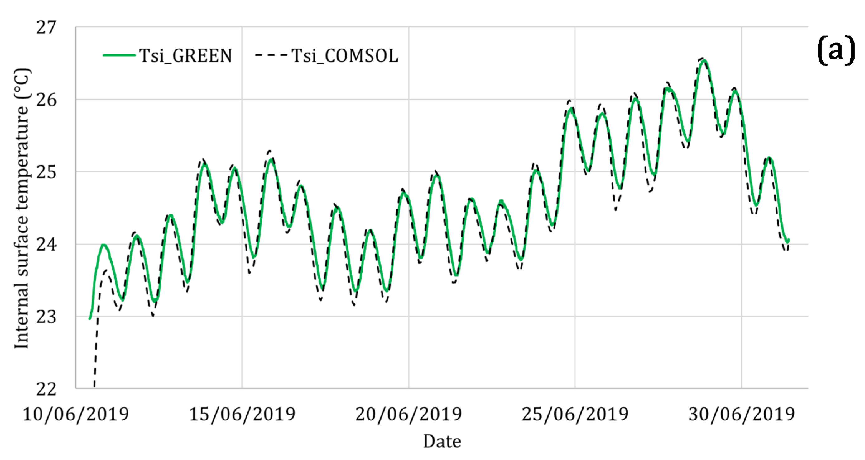
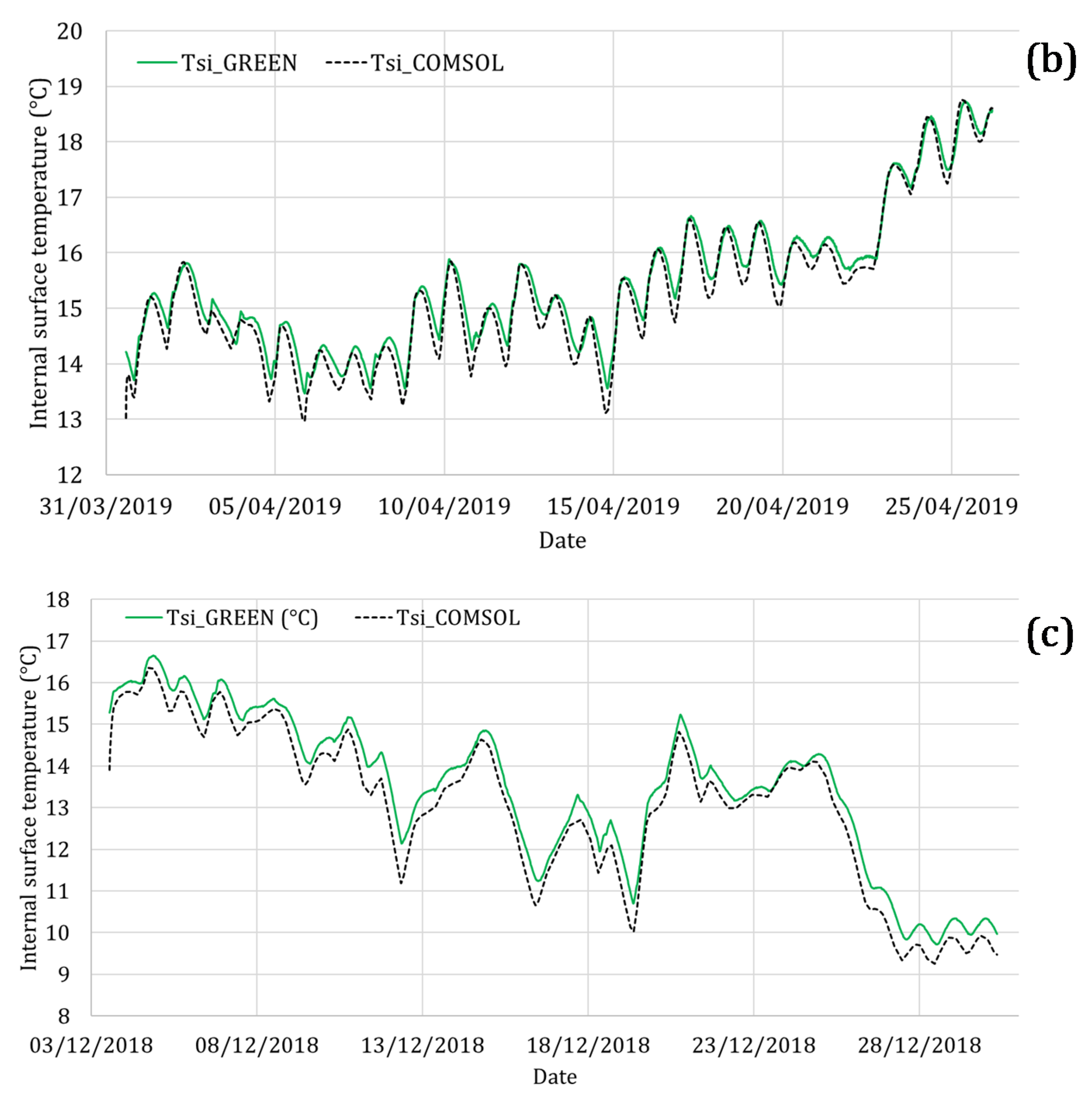
3.3. Building Energy Simulations

The equivalent thermophysical properties defined in the previous section were used as inputs in the building energy software, in order to simulate the influence of the green roof on the annual energy needs. As mentioned in the methodology section, a simple detached building was created by means of TRNSYS software.
Comparing the effects related to the installation of the green roof respect to the original one, Figure 10 shows the difference between the annual heating and cooling energy needs. It is possible to observe a percentage difference equal to −21.14% for heating and −34.70% for cooling.
In addition, the energy simulations were performed, taking into account different climatic conditions. Following the climatic classification reported in [28], Table 2 lists the heating and cooling energy needs obtained using four different weather data: Rome, Manaus, Abu Dhabi and Moscow were considered as references for mild temperate, tropical, dry and snowy conditions, respectively. Comparing the green and the original roofs, the values reported in Table 2 always obtain negative percentage variations, highlighting that the green roof could be applied under different climatic conditions, showing positive effects during winter and summer.
Starting from the obtained results, it is possible to affirm that the green roof has a good insulating effect, reducing the energy needs of the building in cold seasons and keeping it cooler under warm climatic conditions (due to its inertial behavior). It is worth mentioning that a green roof can also protect the roof’s materials from temperature fluctuations, ensuring the transpiration of the layers.

4. Conclusions

A green roof, installed on an actual building, was examined through on-site measurements. Several measuring instruments were applied for monitoring heat transfers phenomena across the green roof, making a comparison with a nearby conventional roof. Due to difficulties modelling the green part of the roof, an equivalent model was generated for obtaining equivalent thermophysical properties to be used in building energy simulation tools.
The outcomes of this study conclude that:
  • The comparison between the original and the green roof reveals that the roof-lawn system has a more stable thermal behavior, during both summer and winter seasons;
  • Making a comparison between the green and the original roofs U-values, a percentage difference of about −55% was highlighted, demonstrating a significant insulating effect of the green roof;
  • The roof-lawn system significantly increases the inertial behavior of the roof, generating higher thermal comfort in the indoor environment for occupants;
  • The equivalent thermophysical properties were found and verified during summer, middle season and winter, thus demonstrating the effectiveness and the reliability of the assessed values;
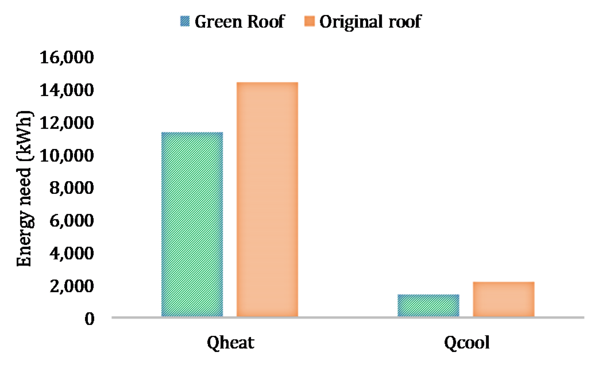
  • A significant reduction in the energy needs of the building was achieved: when simulating the roof-lawn system compared to the original roof, percentage differences of −21.14% and −34.70% were obtained for heating and cooling, respectively.
Green roofs have a thermal insulation function, known since ancient times. It is therefore true that this kind of systems involve higher initial costs, which can be amortized quickly [7]. Green roofs are also a natural barrier against noise pollution. The green roof can absorb external noise by reducing the reflection of sound. In addition, greenery produces oxygen and captures CO2 and polluting agents, representing a natural countermeasure against air pollution. Among passive solutions, green roofs represent a sustainable answer, reducing the collateral effect of the Urban Heat Island phenomenon.
Future developments will concern the optimization of the structural part of the roof, and designing a stratigraphy able to better work with the overlying roof-lawn.

Author Contributions

Data curation, C.G. and L.E.; Formal analysis, C.G. and L.E.; Methodology, C.G., L.E., F.A. and R.D.L.V.; Supervision, F.A. and R.D.L.V.; Writing—original draft, C.G. and L.E.; Writing—review & editing, F.A. and R.D.L.V. All authors have read and agreed to the published version of the manuscript.

Funding

This research received no external funding.

Conflicts of Interest

The authors declare no conflict of interest.

Nomenclature

CThermal conductance [W/(m2K)]
hintInternal heat transfer coefficient [W/(m2K)]
qHeat flux density [W/m2]
TTemperature at the boundary of the geometry [K, °C]
TeOutdoor air temperature [K, °C]
TenvTemperature outside the simulated domain [K, °C]
TiIndoor air temperature [K, °C]
TseExternal surface temperature [K, °C]
TsiInternal surface temperature [K, °C]
UThermal transmittance [W/(m2K)]
TTime [h, min]
MAXMaximum value
MINMinimum value
PSPhase shift [h]
DFDecrement factor [-]

References

  1. Guattari, C.; Evangelisti, L.; Balaras, C. On the assessment of urban heat island phenomenon and its effects on building energy performance: A case study of Rome (Italy). Energy Build. 2018, 158, 605–615. [Google Scholar] [CrossRef]
  2. Mohajerani, A.; Bakaric, J.; Jeffrey-Bailey, T. The urban heat island effect, its causes, and mitigation, with reference to the thermal properties of asphalt concrete. J. Environ. Manag. 2017, 197, 522–538. [Google Scholar] [CrossRef] [PubMed]
  3. Rizwan, A.M.; Dennis, L.Y.C.; Liu, C. A review on the generation, determination and mitigation of Urban Heat Island. J. Environ. Sci. 2008, 20, 120–128. [Google Scholar] [CrossRef]
  4. Castiglia Feitosa, R.; Wilkinson, S.J. Attenuating heat stress through green roof and green wall retrofit. Energy Build. 2018, 140, 11–22. [Google Scholar] [CrossRef]
  5. Jim, C.Y. Green roof evolution through exemplars: Germinal prototypes to modern variants. Sustain. Cities Soc. 2017, 35, 69–82. [Google Scholar] [CrossRef]
  6. Besir, A.; Cuce, E. Green roofs and facades: A comprehensive review. Renew. Sustain. Energy Rev. 2018, 82, 915–939. [Google Scholar] [CrossRef]
  7. Shafique, M.; Kim, R.; Rafiq, M. Green roof benefits, opportunities and challenges—A review. Renew. Sustain. Energy Rev. 2018, 90, 757–773. [Google Scholar] [CrossRef]
  8. Solcerova, A.; van de Ven, F.; Wang, M.; Rijsdijk, M.; van de Giesen, N. Do green roofs cool the air? Build. Environ. 2017, 111, 249–255. [Google Scholar] [CrossRef] [Green Version]
  9. Imran, H.M.; Kala, J.; Ng, A.W.M.; Muthukumaran, S. Effectiveness of green and cool roofs in mitigating urban heat island effects during a heatwave event in the city of Melbourne in southeast Australia. J. Clean. Prod. 2018, 197, 393–405. [Google Scholar] [CrossRef]
  10. Yang, J.; Kumar, D.I.M.; Pyrgou, A.; Chong, M.; Santamouris, D.; Kolokotsa, S.E. Lee, Green and cool roofs’ urban heat island mitigation potential in tropical climate. Sol. Energy 2018, 173, 597–609. [Google Scholar] [CrossRef]
  11. Zhang, Q.; Liping, M.; Wang, X.; Liu, D.; Zhou, B.; Zhu, L.; Sun, J.; Liu, J. The capacity of greening roof to reduce stormwater runoff and pollution. Landsc. Urban Plan. 2015, 144, 142–150. [Google Scholar] [CrossRef]
  12. Wang, H.; Qin, J.; Hu, Y. Are green roofs a source or sink of runoff pollutants? Ecol. Eng. 2017, 107, 65–70. [Google Scholar] [CrossRef]
  13. Teotonio, I.; Matos Silva, C.; Oliveira Cruz, C. Eco-solutions for urban environments regeneration: The economic value of green roofs. J. Clean. Prod. 2018, 199, 121–135. [Google Scholar] [CrossRef]
  14. Huang, Y.Y.; Chen, C.T.; Liu, W.T. Thermal performance of extensive green roofs in a subtropical metropolitan area. Energy Build. 2018, 159, 39–53. [Google Scholar] [CrossRef]
  15. Khabaz, A. Construction and design requirements of green buildings’ roofs in Saudi Arabia depending on thermal conductivity principle. Constr. Build. Mater. 2018, 186, 1119–1131. [Google Scholar] [CrossRef]
  16. Ziogou, I.; Michopolous, A.; Voulgari, V.; Zachariadis, T. Implementation of green roof technology in residential buildings and neighborhoods of Cyprus. Sustain. Cities Soc. 2018, 40, 233–243. [Google Scholar] [CrossRef]
  17. Asdrubali, F.; Evangelisti, L.; Guattari, C.; Marzi, A.; Roncone, M. Monitoraggio e simulazione dinamica di un edificio pilota dotato di tette verd. Aicarr. J. 2019, 59, 40–44. [Google Scholar] [CrossRef] [Green Version]
  18. Liu, K.; Baskaran, B. Thermal performance of green roofs through field evaluation. In Proceedings of the First North American Green Roof Infrastructure Conference, Awards and Trade Show, Chicago, IL, USA, 29–30 May 2003. [Google Scholar]
  19. Liu, K.; Baskaran, B. Thermal Performance of extensive green roofs in cold climate. In Proceedings of the 2005 World Sustainable Building Conference, Tokyo, Japan, 27–29 September 2005. [Google Scholar]
  20. Bindi Prato Pronto. Available online: http://www.pratopronto.it/index.php?option=com_content&view=article&id=51&Itemid=57 (accessed on 3 March 2020).
  21. ISO 9869-1. Thermal Insulation: Building Elements—In-Situ Measurement of Thermal Resistance and Thermal Transmittance. Part 1: Heat Flow Meter Method; ISO: Geneva, Switzerland, 2015. [Google Scholar]
  22. Kontoleon, K.J.; Bikas, D.K. The effect of south wall’s outdoor absorption coefficient on time lag, decrement factor and temperature variations. Energy Build. 2007, 39, 1011–1018. [Google Scholar] [CrossRef]
  23. COMSOL Multiphysics, version 5.2. Available online: www.comsol.com (accessed on 9 January 2020).
  24. Guattari, C.; Evangelisti, L.; Gori, P.; Asdrubali, F. Influence of internal heat sources on thermal resistance evaluation through the heat flow meter method. Energy Build. 2018, 135, 187–200. [Google Scholar] [CrossRef]
  25. Evangelisti, L.; Guattari, C.; Gori, P.; Asdrubali, F. Assessment of equivalent thermal properties of multilayer building walls coupling simulations and experimental measurements. Build. Environ. 2018, 127, 77–85. [Google Scholar] [CrossRef]
  26. Evangelisti, L.; Guattari, C.; Gori, P.; de Lieto Vollaro, R.; Asdrubali, F. Experimental investigation of the influence of convective and radiative heat transfers on thermal transmittance measurements. Int. Commun. Heat Mass 2016, 78, 214–223. [Google Scholar] [CrossRef]
  27. Levinson, R. Cool Roofs, Cool Cities, Cool Planet. In Proceedings of the China’s National Development and Reform Commission Delegation to LBNL, Berkeley, CA, USA, 22 April 2010. [Google Scholar]
  28. Evangelisti, L.; Asdrubali, G.F. On the sky temperature models and their influence on buildings energy performance: A critical review. Energy Build. 2019, 183, 607–625. [Google Scholar] [CrossRef]
Figure 1. (a) Single-story building on which the green roof is installed and (b) roof-lawn whole system (an elaboration from [20]).
Applsci 10 01767 g001
Figure 2. Green roof stratigraphy.
Applsci 10 01767 g002
Figure 3. Measurement apparatus schema.
Applsci 10 01767 g003
Figure 4. Methodological approach flow-chart.
Applsci 10 01767 g004
Figure 5. Heat fluxes, indoor temperatures and internal surface temperatures registered during winter for the green roof (a) and the original one (b).
Applsci 10 01767 g005
Figure 6. Green roof and original roof U-values.
Applsci 10 01767 g006
Figure 7. Heat fluxes, indoor temperatures and internal surface temperatures registered during middle season for the green roof (a) and the original one (b).
Applsci 10 01767 g007
Figure 8. Heat fluxes, indoor temperatures and internal surface temperatures registered during summer for the green roof (a) and the original one (b).
Applsci 10 01767 g008aApplsci 10 01767 g008b
Figure 9. Green roof equivalent model. Comparison between measured and simulated internal surface temperature: summer (a); middle season (b); winter (c).
Applsci 10 01767 g009aApplsci 10 01767 g009b
Figure 10. Comparison between annual heating and cooling energy needs.
Applsci 10 01767 g010
Table 1. Measuring instruments technical data.
Measuring InstrumentManufacturerModelMeasuring RangeResolutionAccuracy
Heat-flow sensorHuksefluxHFP01−2000 ÷ 2000 W/m20.01 W/m25% on 12 h
ThermometerLSIPt100−40 ÷ 80 °C0.01 °C0.10 °C (0 °C)
Surface temperature sensorLSIEST124−40 ÷ 80 °C0.01 °C0.15 °C (0 °C)
Table 2. Comparison among heating and cooling energy needs in different climatic conditions.
RomeManausAbu DhabiMoscow
HeatingCoolingQheatQcoolQheatQcoolQheatQcool
Green roof11,388 kWh1439 kWh0 kWh4798 kWh379 kWh10,597 kWh34,529 kWh42 kWh
Original roof14,442 kWh2205 kWh0 kWh7168 kWh654 kWh14,197 kWh42,807 kWh113 kWh
Variation−21.14%−34.70%-−33.06%−42.03%−25.36%−19.34%−62.90%

