Numerical Analysis of the Impact of Thermal Spray Insulation Solutions on Floor Loading


Abstract
1. Introduction
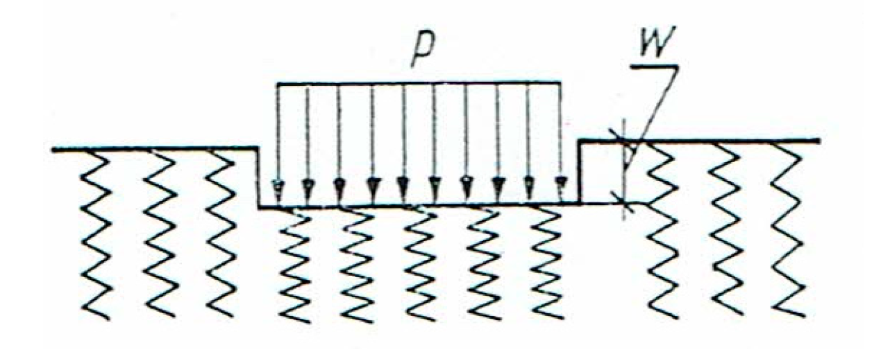
- p—load [kN/m2]
- w—deflection [m]
- Kz—subgrade stiffness [kN/m3]
2. Materials and Methods
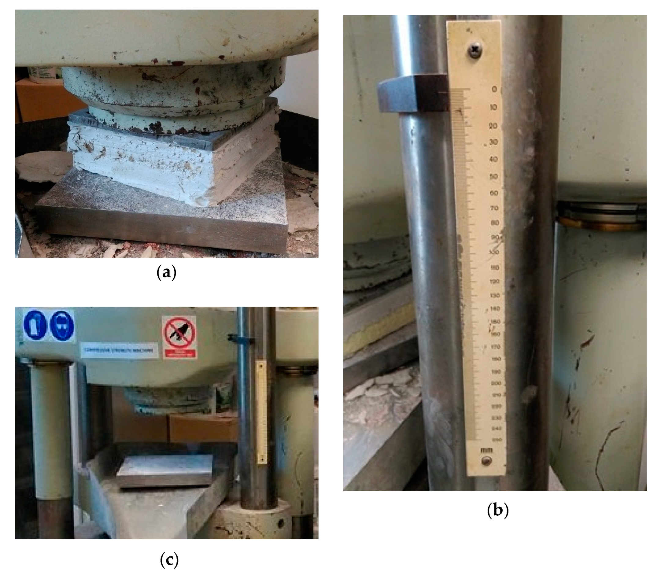
2.1. Laboratory Tests
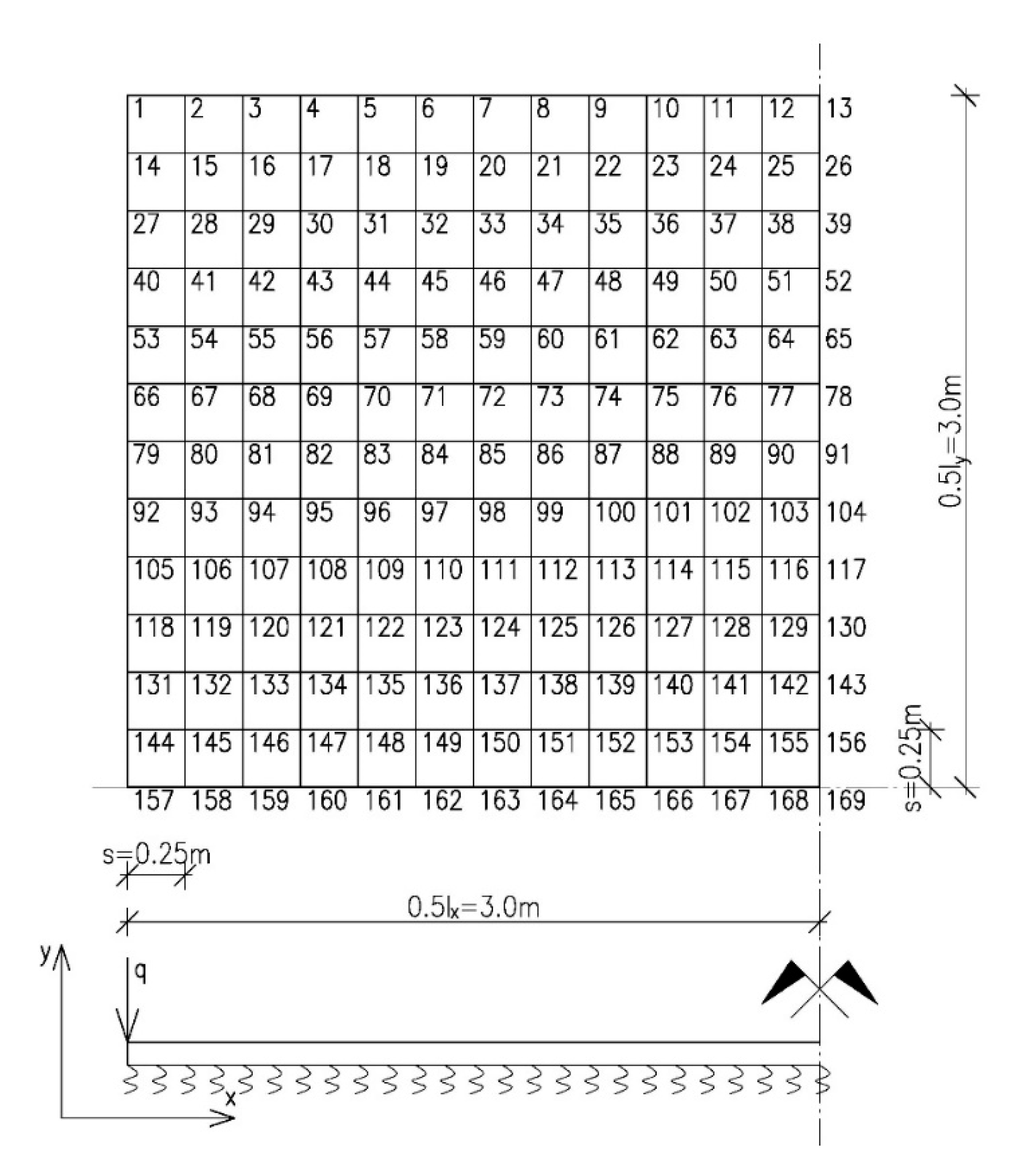
2.2. Static Calculations for the Plate
- D = —plate flexural rigidity,
- E—elasticity modulus of material,
- v—Poisson’s ratio,
- h—plate thickness,
- w—plate deflection,
- q—load perpendicular to the central surface of the plate,
- A—plate area,
- K—subgrade stiffness reaction.
3. Results
- —bending moment at the node k,
- —plate flexural rigidity,
- —deflections at particular nodes of the grid.
4. Discussion
5. Conclusions
Funding
Acknowledgments
Conflicts of Interest
References
- Kurt, M.; Slavkin, I.; Eriten, M.; McFarland, D.M.; Gendelman, O.L.; Bergman, L.A.; Vakakis, A.F. Effect of 1:3 resonance on the steady-state dynamics of a forced strongly nonlinear oscillator with a linear light attachment. Arch. Appl. Mech. 2014, 84, 1189–1203. [Google Scholar] [CrossRef]
- Kurt, M.; Eriten, M.; McFarland, D.M.; Bergman, L.A.; Vakakis, A.F. Strongly nonlinear beats in the dynamics of an elastic system with a strong local stiffness nonlinearity: Analysis and identification. J. Sound Vib. 2014, 333, 2054–2072. [Google Scholar] [CrossRef]
- Małasiewicz, A.; Tejchman, J. Industrial Floors; Gdańsk University of Technology Publishing House: Gdańsk, Poland, 2006. [Google Scholar]
- Ksit, B.; Szymczak-Graczyk, A. Examples of repair and renovation of industrial floors. Acta Sci. Pol. Archit. 2019, 18, 91–98. [Google Scholar] [CrossRef]
- Jasiczak, J. Industrial floors. In Materials, Technologies, Design, Repairs; Addiment Polska Sp. z o.o.: Poznań, Poland, 2001. [Google Scholar]
- Hajduk, P. Monolithic concrete floors. Inżynier Budownictwa 2018, 11, 85–88. Available online: http://www.inzynierbudownictwa.pl/technika,materialy_i_technologie,artykul,monolityczne_podlogi_betonowe_jak_unikac_bledow_cz_i,11298,4 (accessed on 10 October 2019).
- Deręgowska, B.; Szymczak-Graczyk, A. Evaluation of the suitability of polyurethane foam boards treated as underfloor elastic substrate. Mater. Bud. 2017, 537, 126–127. [Google Scholar] [CrossRef]
- Frydrych, K. Studies on Shaping the Value of the Susceptibility Coefficient of the Substrate for Static Calculations of Tunnel Housings. Ph.D. Thesis, AGH, Kraków, Poland, 2012. Available online: https://docplayer.pl/2825799-Badania-nad-ksztaltowaniem-sie-wartosci-wspolczynnika-podatnosci-podloza-dla-celow-obliczen-statycznych-obudowy-tuneli.html (accessed on 10 October 2019).
- Urbanowski, W. Case studies of bending a round plate connected to a flexible substrate of generalized properties. Zeszyty Naukowe Politechniki Warszawskiej 1956, 3, 33–61. [Google Scholar]
- Blakov, B.Z.; Leontev, H.H. Beams, Plates and Shells on an Elastic Foundation; Г.И.Φ.M.Л.: Mokkva, Russia, 1960. [Google Scholar]
- Kączkowski, Z. Plates. Static Calculations; Arkady: Warszawa, Poland, 2000. [Google Scholar]
- Szcześniak, W.; Ataman, M. Vibration of beam resting on the inertial Vlasov-Leontiev foundation under impulse of force. Autobusy 2016, 3, 727–732. Available online: https://www.infona.pl/resource/bwmeta1.element.baztech-f141ed93-eaec-4f11-859d-6597145c47f7 (accessed on 10 October 2019).
- Wang, Y.H.; Tham, L.G.; Cheung, Y.K. Beams and plates on elastic foundations: A review. Prog. Struct. Eng. Mater. 2005, 7, 174–182. [Google Scholar] [CrossRef]
- Ryżyński, W.; Karczewski, B. Determination of calculation parameters of the layered substrate under industrial floors. Nowocz. Hale 2014, 5, 34–38. Available online: https://www.astra-polska.com/wp-content/uploads/2014/11/5_2014-HAL.pdf (accessed on 10 October 2019).
- Korhan, O.; Ayse, T.D. Free vibration analysis of thick plates on elastic foundations using modified Vlasov model with higher order finite elements. Int. J. Econ. Manag. 2012, 19, 279–291. [Google Scholar]
- Ignaczewski, R. Modern polyurethane insulation systems—Effective protection against heat loss. Izolacje 2017, 1, 44–45. [Google Scholar]
- Migda, W.; Szczepański, M.; Jankowski, R. Increasing the seismic resistance of wood-frame buildings by applying PU foam as thermal insulation. Period. Polytech. Civ. Eng. 2019, 63, 480–488. [Google Scholar] [CrossRef]
- Suman, B.M.; Srivastava, R.K. Influence of thermal insulation on conductive heat transfer through roof ceiling construction. J. Sci. Ind. Res. 2009, 68, 248–251. Available online: Http://hdl.handle.net/123456789/3145 (accessed on 10 October 2019).
- Václavík, V.; Valíček, J.; Dvorský, T.; Hryniewicz, T.; Rokosz, K.; Harničárová, M.; Kušnerová, M.; Daxner, J.; Bendová, M. A method of utilization of polyurethane after the end of its life cycle. Annu. Set. Environ. Prot. 2012, 14, 96–106. Available online: http://ros.edu.pl/images/roczniki/archive/pp_2012_005.pdf (accessed on 10 October 2019).
- Liszkowska, J.; Moraczewski, K.; Borowicz, M.; Paciorek-Sadowska, J.; Czupryński, B.; Isbrandt, M. The effect of accelerated aging conditions on the properties of rigid polyurethane-polyisocyanurate foams modified by cinnamon extract. Appl. Sci. 2019, 9, 2663. [Google Scholar] [CrossRef]
- Polish Standard: PN-EN 826: 1998 Determination of Compression Behavior of Thermal Insulation Products; Polish Committee for Standardization: Warsaw, Poland, 1998.
- Polish Standard: PN-EN 13165:2010 Products for Thermal Insulation in Construction; Rigid Polyurethane Foam Products (PUR) Manufactured in the Factory—Specification; Polish Committee for Standardization: Warsaw, Poland, 2010.
- Schneider, D.; Szymczak-Graczyk, A. Determination of the polyurethane foam shear modulus In Situ. Mater. Bud. 2019, 557, 62–63. [Google Scholar] [CrossRef]
- Gołaś, J. Introduction to the Theory of Plates; Opole University of Technology Publishing House: Opole, Poland, 1972. [Google Scholar]
- Donnell, L.H. Beams, Plates and Shells; McGraw-Hill: New York, NY, USA, 1976. [Google Scholar]
- Naghdi, P.M. The Theory of Shells and Plates; Handbuch der Physick; Springer: Berlin/Heidelberg, Germany, 1972. [Google Scholar]
- Panc, V. Theries of Elastic Plates; Academia: Prague, Czech Republic, 1975. [Google Scholar]
- Timoshenko, S.; Woinowsky-Krieger, S. Theory of Plates and Coatings; Arkady: Warszawa, Poland, 1962. [Google Scholar]
- Szlilard, R. Theory and analysis of plates. In Classical and Numerical Methods; Cliffs: Englewood, NJ, USA; Prentice-Hall: Upper Saddle River, NJ, USA, 1974. [Google Scholar]
- Ugural, A.C. Stresses in Plates and Shells; McGraw-Hill: New York, NY, USA, 1981. [Google Scholar]
- Wilde, P. Variational approach of finite differences in the theory of plate. In Proceedings of the Materials of XII Scientific Conference of the Committee of Science PZiTB and the Committee of Civil Engineering of Polish Academy of Sciences, Krynica, Poland, IX 1966. [Google Scholar]
- Kollár, L. Some problems of static analysis of folded plate structures. Period. Polytech. Civ. Eng. 1993, 37, 168–202. [Google Scholar]
- Tribiłło, R. Application of the generalized finite difference method for plate calculations. Archiwum Inżynierii Lądowej 1975, 2, 579–586. [Google Scholar]
- Son, M.; Sang Jung, H.; Hee Yoon, H.; Sung, D.; Suck Kim, J. Numerical study on scale Effect of repetitive plate-loading test. Appl. Sci. 2019, 9, 4442. [Google Scholar] [CrossRef]
- Szymczak-Graczyk, A. Rectangular plates of a trapezoidal cross-section subjected to thermal load. In IOP Conference Series: Materials Science and Engineering; IOP Publishing: Bristol, UK, 2019; Volume 603, p. 032095. [Google Scholar] [CrossRef]
- Buczkowski, W.; Szymczak-Graczyk, A.; Walczak, Z. Experimental validation of numerical static calculations for a monolithic rectangular tank with walls of trapezoidal cross-section. Bull. Pol. Acad. Sci. Tech. Sci. 2017, 65, 799–804. [Google Scholar] [CrossRef]
- Szymczak-Graczyk, A. Floating platforms made of monolithic closed rectangular tanks. Bull. Pol. Acad. Sci. Tech. Sci. 2018, 66, 209–219. [Google Scholar] [CrossRef]
- Schneider, D. Analysis of the Influence of Thermal Insulation in the Calculations of the Load Floor Capacity. Master’s Thesis, Poznan University of Life Sciences, Poznań, Poland, 2018. [Google Scholar]
- Szymczak-Graczyk, A.; Ksit, B.; Laks, I. Operational problems in structural nodes of reinforced concrete constructions. In IOP Conference Series: Materials Science and Engineering; IOP Publishing: Bristol, UK, 2019; Volume 603, p. 032096. [Google Scholar] [CrossRef]
- Johansson, M. Reinforcement detailing in concrete frame corners. ACI Struct. J. 2001, 98, 105–115. [Google Scholar]
- British Standard: BS 8204-2:2002 Screeds, Bases and In Situ Floorings; Concrete Wearing Surfaces. Code of Practice; British Committee for Standardization: London, UK, 2002.
- Concrete Industrial Ground Floors—A Guide to Their Design and Construction; Technical Raport 34 Fourth Edition; The Concrete Society: Oxford, UK, 2014.


| Thickness of the Sample [cm] | Average Compressive Stresses at 10% Relative Strain for a Given Thickness [kPa] | Average Subgrade Stiffness Reaction for a Given Thickness K [kN/m3] | Average Subgrade Stiffness Reaction K [kN/m3] |
|---|---|---|---|
| 16 | 300.0 | 18,750 | 32,073 |
| 14.5 | 305.0 | 21034 | |
| 14 | 320.0 | 22,857 | |
| 13.5 | 320.0 | 23,704 | |
| 13 | 320.5 | 24,654 | |
| 12.5 | 325.0 | 26,000 | |
| 12 | 327.5 | 27,292 | |
| 10.5 | 336.3 | 32,024 | |
| 9.5 | 338.3 | 35,614 | |
| 9 | 340.0 | 37,778 | |
| 8.5 | 357.7 | 41,372 | |
| 8 | 357.8 | 44,719 | |
| 7.5 | 312.5 | 41,667 | |
| 7 | 360.8 | 51,548 |
| Discretisation Grid Points | The Concrete Slab Resting on the Subgrade Stiffness K = 32,000 kN/m3 | The Concrete Slab Resting on the Substrate Subgrade Stiffness K = 50,000 kN/m3 | Multiplier |
|---|---|---|---|
| 157 | 0 | 0 | qs2 |
| 158 | −0.833 | −0.811 | |
| 159 | −1.388 | −1.316 | |
| 160 | −1.723 | −1.582 | |
| 161 | −1.889 | −1.732 | |
| 162 | −1.931 | −1.834 | |
| 163 | −1.970 | −1.886 | |
| 164 | −1.996 | −1.913 | |
| 165 | −2.004 | −1.949 | |
| 166 | −2.065 | −1.986 | |
| 167 | −2.118 | −1.998 | |
| 168 | −2.152 | −2.048 | |
| 169 | −2.273 | −2.069 |
| Concrete Slab | Deflections [qs4/D] | Bending Moments [qs2] Mx = My | Decrease in the Value of Bending Moment [%] |
|---|---|---|---|
| Resting on the substrate with subgrade stiffness K = 32,000 kN/m3 | w169 = 35.635 | M169 = −2.273 | - |
| Resting on the substrate with subgrade stiffness K = 50,000 kN/m3 | w169 = 23.236 | M169 = −1.886 | 17.03 |
© 2020 by the author. Licensee MDPI, Basel, Switzerland. This article is an open access article distributed under the terms and conditions of the Creative Commons Attribution (CC BY) license (http://creativecommons.org/licenses/by/4.0/).
Share and Cite
Szymczak-Graczyk, A. Numerical Analysis of the Impact of Thermal Spray Insulation Solutions on Floor Loading. Appl. Sci. 2020, 10, 1016. https://doi.org/10.3390/app10031016
Szymczak-Graczyk A. Numerical Analysis of the Impact of Thermal Spray Insulation Solutions on Floor Loading. Applied Sciences. 2020; 10(3):1016. https://doi.org/10.3390/app10031016
Chicago/Turabian StyleSzymczak-Graczyk, Anna. 2020. "Numerical Analysis of the Impact of Thermal Spray Insulation Solutions on Floor Loading" Applied Sciences 10, no. 3: 1016. https://doi.org/10.3390/app10031016
APA StyleSzymczak-Graczyk, A. (2020). Numerical Analysis of the Impact of Thermal Spray Insulation Solutions on Floor Loading. Applied Sciences, 10(3), 1016. https://doi.org/10.3390/app10031016