Article

Techno-Economic Analysis of a Heat Pump Cycle Including a Three-Media Refrigerant/Phase Change Material/Water Heat Exchanger in the Hot Superheated Section for Efficient Domestic Hot Water Generation

1
AIT Austrian Institute of Technology, Center for Energy, Giefinggasse 2, 1210 Wien, Austria
2
GREiA Research Group, Universitat de Lleida, Pere de Cabrera s/n, 25001 Lleida, Spain
3
AKG Verwaltungsgesellschaft mbH, Am Hohlen Weg 31, 34369 Hofgeismar, Germany
4
OCHSNER Wärmepumpen GmbH, Krackowizerstraße 4, 4020 Linz, Austria
5
Pink GmbH, Bahnhofstrasse 22, 8665 Langenwang, Austria
*
Author to whom correspondence should be addressed.
Appl. Sci. 2020, 10(21), 7873; https://doi.org/10.3390/app10217873
Submission received: 16 October 2020 / Revised: 2 November 2020 / Accepted: 4 November 2020 / Published: 6 November 2020
(This article belongs to the Special Issue Design and System Integration of Thermal Energy Storage)

Abstract

:
Integration of a three-media refrigerant/phase change material (PCM)/water heat exchanger (RPW-HEX) in the hot superheated section of a heat pump (HP) system is a promising approach to save energy for domestic hot water (DHW) generation in multi-family houses. The RPW-HEX works as a desuperheater and as a latent thermal energy storage in the system. The latent thermal energy storage is charged during heating and cooling operation and discharged for DHW production. For this purpose, the water side of the RPW-HEX is connected to decentralized DHW storage devices. DHW consumption, building standards and climate, energy prices, material costs, and production costs are the constraints for the selection of the optimal storage size and RPW-HEX design. This contribution presents the techno-economic analysis of the RPW-HEX integrated into an R32 air source HP. With the aid of experimentally validated dynamic computer models, the optimal sizing of the RPW-HEX storage is discussed to maximize energy savings and to minimize the investment costs. The results are discussed in the context of a return of investment analysis, practical implementation aspects and energetic potential of the novel technology.

1. Introduction

Today’s commercially available air source heat pumps (HPs) work highly efficient and make a valuable contribution to achieve climatic goals such as the reduction in the amount of CO2 in our atmosphere. In the United States, for example, the share of HP sales for newly constructed buildings exceeds 40% for single-family dwellings, and is nearly 50% for new multi-family buildings. In addition, the EU market is expanding quickly, with 12% annual average growth since 2015. France, Italy and Spain are responsible for half of all sales in the European Union, while Sweden, Estonia, Finland and Norway have the highest penetration rates, with more than 25 HPs sold per 1000 households each year [1].
Different concepts using latent heat thermal energy storage technologies together with HPs were proposed in the past to further increase the efficiency of the state-of-the-art HPs. Usually, the main aim of such storage technologies is to decrease the size of buffer tanks and domestic hot water (DHW) storage devices, to avoid the oversizing of HPs by reducing thermal peak loads and ON/OFF-cycles by shifting heating and cooling demands in time, to optimize the integration of solar thermal collectors, to enhance the defrosting performance of air source HPs or to reduce the size of a ground-source heat exchanger by the use of PCMs in boreholes [2,3,4,5,6,7]. This wide range of applications with PCMs in combination with HPs was made possible by the availability of PCM materials over a wide temperature spectrum [8,9,10].
In most of the reported studies, HP compressors with fixed speed were investigated. The performance of these systems was mainly increased by reducing the ON/OFF cycles with the aid of the latent storages. Applications with variable speed compressors designed for heating and DHW generation are usually not the focus for combined systems with PCMs [2,3]. In the latter, the benefits of using PCM storage, besides a reduced size, usually result from an energy shift from times with high to times with low electricity prices and from the possibility to scale down the HP capacities, and therefore from reducing investment costs.
Applications with PCMs used to store the sensible heat of the hot gas in the superheated section of a HP after the compressor are not known to the authors. However, the concept of using this heat directly to improve the overall performance of DHW heating has been studied for many years [11,12]. The sensible energy which is available at a higher temperature level as the condensing temperature is described as a desuperheater, which is usually an additional small heat exchanger that is installed directly after the compressor and before the actual condenser of the HP. The desuperheater can either be integrated directly into a stratified storage, as in [13], or connected via a secondary water cycle to a DHW storage, as in [14].
The present work employs an integrated three-media refrigerant/phase change material (PCM)/water heat exchanger (RPW-HEX) as a kind of desuperheater-storage combined with a HEX in the hot gas section after the compressor of an air source HP. For this purpose, the water side of the RPW-HEX is connected to decentralized DHW storage devices located in individual apartments of a multi-family house.
The original concept was first presented in [15] and results were presented for the annual performance of a low energy building located in an average European climate (Strasbourg, France). The results were computed adopting a quasi-static approach similar to the one used in the EN14825 standard [16] for air source HPs. A payback time of 18 years and annual energy savings of 200 kWhel were found in this study. However, due to these simplified calculation methods used in [15], several aspects could not be addressed properly:
  • the possibility to pre-heat the process water with the HP’s condenser during energy efficient DHW generation (compared with operating mode (c) in Section 2.1 and Appendix A);
  • the limitations in the storage capacity of the RPW-HEX and the DHW storage devices;
  • the heat losses to the surrounding of the RPW-HEX and the decentralized DHW storage devices;
  • the solar radiation, ventilation rates and many other constraints of the building;
  • the control strategy.
All these points are considered in the present study. Contrary to the previous work, a fan coil system for heating and cooling is considered instead of a floor heating/cooling system, allowing us to use lower temperatures for cooling and dehumidification in summer. Additionally, in the present work, storage capacities and operating modes were varied to find an optimal RPW-HEX storage size for three different application examples. Furthermore, investment- and operation-related costs are estimated, and payback times and profits after 20 years are calculated.

2. Case Studies and Operation Modes of the System

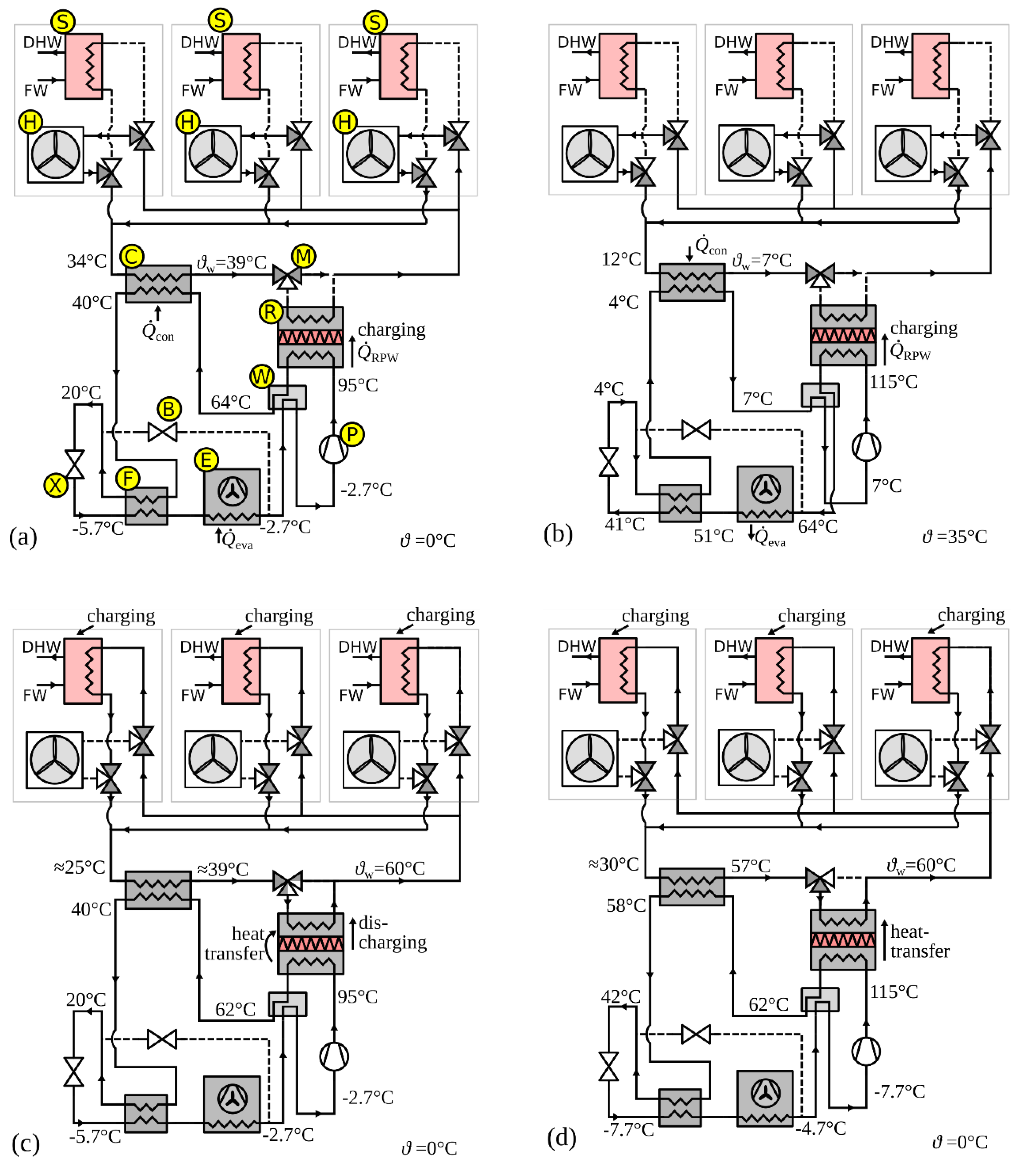
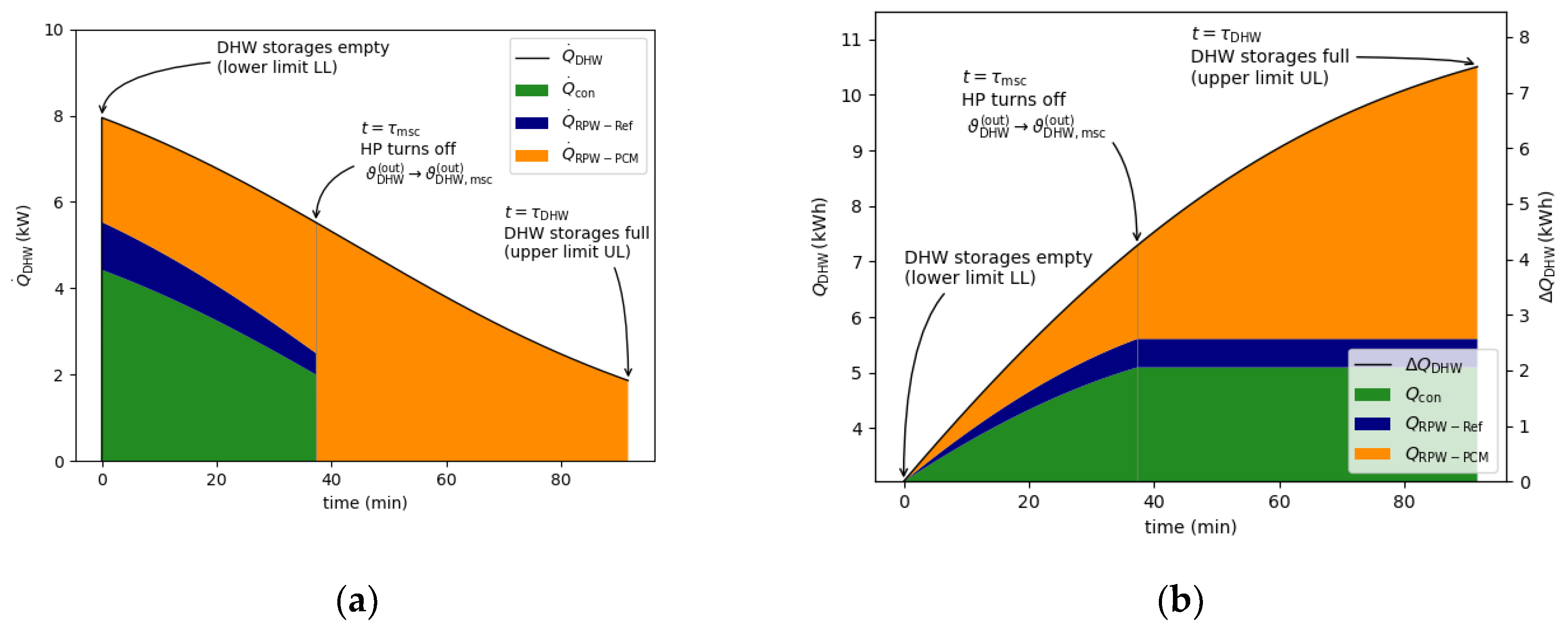
2.1. Operation Modes of the HP with Integrated RPW-HEX

The proposed system distinguishes between six operating modes (a–f), whilst a conventional system distinguishes mainly between three operating modes, namely heating, cooling and DHW generation, which have similar efficiencies to operating modes (d), (e), and (f) in the proposed system:
(a)
heating operation and charging the RPW-HEX (0 < SoC↑ ≤ 1)
(b)
cooling operation and charging the RPW-HEX (0 < SoC↑ ≤ 1)
(c)
energy efficient DHW generation by discharging the RPW-HEX and pre-heating via the condenser (0 ≤ SoC↓ ≤ 1)
(d)
conventional (inefficient) direct DHW generation (SoC = 0)
(e)
heating operation when the RPW-HEX is fully charged (SoC = 1)
(f)
cooling operation when the RPW-HEX is fully charged (SoC = 1)
where SoC refers to the state of charge of the RPW-HEX [17]. Figure 1a-d show the operation modes (a)–(d) in a simplified system sketch with three apartments connected to the HP system as an example. The conventional operation modes (e) and (f) are omitted in the sketch for the sake of brevity. The HP is connected to the apartments with two hydraulic lines and the switching between charging the decentralized DHW storage, and heating/cooling takes place in the apartments. During heating mode (a), most of the sensible energy in the superheated hot gas charges the RPW-HEX (R). The amount of transferred heat depends on the hot gas temperature, the refrigerant mass flow, the phase transition temperature of the (solid/liquid) PCM, and the overall heat transfer coefficients of the RPW-HEX. Hot gas temperature and refrigerant mass flow result from the operating point, whereas the switching temperature range of the PCM and the heat transfer capabilities of the RPW-HEX are design-inherent (design parameters). For the proposed concept, R32 as a refrigerant was used and a PCM with a phase transition around 64 °C was selected in all three cases. Please note that it would also be possible to use PCMs with a lower phase transition temperature (e.g., 55 °C), because of the approach with decentralized DHW storage devices, which do not have a problem with legionella. R32 has a rather high hot gas temperature when compared to other refrigerants. To limit the compressor discharge temperature at low temperatures, liquid refrigerant from the condenser exit is injected into the compressor (which can handle a small amount of liquid refrigerant) entrance by means of a liquid injection valve (B). In doing so, the hot gas temperature can be limited to ≈115 °C. Furthermore, an additional HEX (F) is introduced to ensure that the refrigerant is in the liquid phase at the expansion valve (X) entry. Via the condenser (C), the heat is delivered to the apartments by the fan coils (H). Due to the missing contribution of the sensible energy from the hot gas for heating, the condensing pressure is slightly higher in operating mode (a) than in the conventional heating mode (e) for the same water inlet temperature to the heating system. Therefore, the heating COP is slightly smaller in the proposed system compared to a system without RPW-HEX. The inverse behavior is expected for cooling, where the dissipation of energy in the RPW-HEX increases the performance of the evaporator acting as a condenser in operating mode (b). Both contributions lead to a difference in electric energy consumption of typically ±1–3% (see also relative numbers of calculated energy savings for heating and cooling per year in Table 3 for three different cases). In cooling mode (b), the four-way valve (W) switches to reverse mode and the evaporator (E) acts as a heat sink, whereas the condenser (C) cools the building via the heating and cooling network (H). Because the four-way valve (W) is located after the RPW-HEX, the PCM is also charged by the hot gas during the cooling operation. Note that contrary to the heating mode, where it would also be possible to use the energy stored in the PCM for heating (of course with a low exergy efficiency), the energy stored in the RPW-HEX during cooling is usually not used in a conventional air source HP. Once the RPW-HEX is fully charged (SoC = 1) by mode (a) or (b), it would be beneficial if the HP switches to DHW generation mode (c) if the DHW storage devices can be charged. Contrary to direct DHW-generation mode (d), the condensing temperature, and therefore the COP, remains at the values for heating mode (c). Therefore, the process water from the return line of the decentralized DHW storages (S) is pre-heated by the condenser at a beneficial COP (heating COP). Subsequently, the process water is boosted by the RPW-HEX (R) and mixed to the DHW set-point temperature (≈60 °C) by the three-way valve (M). The lower the temperature of the water returning from the DHW storage devices is, the higher the contribution of the condenser of the HP is. Hence, a significant amount of energy need not to be taken out of the RPW-HEX for DHW generation and the performance of the system increases. During this operation mode, the hot gas will additionally transfer its sensible energy via the RPW-HEX (R) to the process water. Once the RPW-HEX is discharged, the HP switches back to heating or cooling mode, respectively.
In the case that the thermal energy for DHW generation cannot be provided entirely by operating mode (c), e.g., during spring, the HP switches to the direct DHW generation mode (d). In this mode, similar to a conventional system, DHW is generated by increasing the condensing temperature to values suitable for DHW. The RPW-HEX acts in this case solely as HEX and transfers the sensible energy of the hot gas directly to process water. During transitional seasons, it would make sense to bypass the RPW-HEX on the refrigerant side (not depicted in the figure) to avoid unnecessary charging/discharging of the RPW-HEX. In operating mode (e) and (f), the RPW-HEX is fully charged, and the modes are comparable to conventional heating and cooling modes.

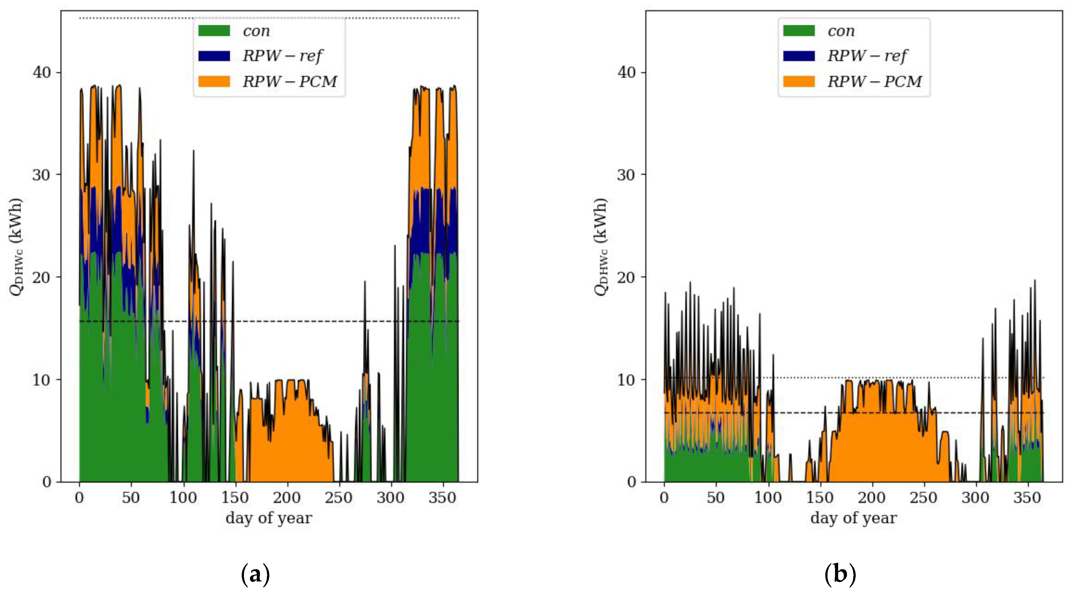
2.2. Control Strategy

The annual performance of the system was calculated considering a rule-based control strategy. Independent of the actual heating or cooling demand, when one of the sensible DHW storage energy levels falls below a lower limit the system switches to DHW generation mode. Depending on the SoC of the RPW-HEX, either operating mode (c) or (d) is triggered. If (c) is triggered, the RPW-HEX is discharged until it is empty (SoC = 0). Note that if one DHW storage triggers the DHW generation mode, all storage will be charged at least to the upper limit to minimize number of switches between heating/cooling and DHW mode. This is also true if the RPW-HEX cannot provide the required energy to charge all DHW storages. In this case, the system switches from operating mode (c) to (d) to complete the charging of the DHW storage. The DHW storage devices are charged sequentially, one after another, up to the upper limit (starting from the storage with the lowest SoC). In addition, it is possible to overcharge the DHW storage devices, above the upper limit, up to a maximum limit if the RPW-HEX is fully charged and it would be beneficial from a systemic point of view to discharge the RPW-HEX. In this case, the DHW storage devices are charged in parallel and not one after another.
If there is heating or cooling demand from the building and the RPW-HEX SoC < 100%, operating mode (a) or (b) are triggered. To avoid constant switching between the heating and cooling mode, e.g., relevant during the transition season or for fast changing external conditions, heating or cooling operation was only triggered after a certain amount energy requirement for heating or cooling, respectively, had been accumulated in the building.

2.3. Case Studies

The system performance is assessed for three different case studies corresponding to three different climatic zones (cold, average and hot climate) with different buildings:
  • Case #1: A passive house located in Helsinki with a “low-temperature heating” distribution system and a PCM with a phase transition at 64 °C
  • Case #2: A low energy building located in Strasbourg with an “intermediate-temperature heating” distribution system and a PCM with a phase transition at 64 °C
  • Case #3: A refurbished building located in Athens with an “intermediate-temperature heating” system and a PCM with a phase transition at 64 °C
To analyze and compare different scenarios, the size of the R32 air source HP was fixed while the sizes of the buildings—more precisely, the number of apartments—were varied. This approach has the advantage that the costs for the HP are fixed for each scenario. In order to calculate scalable heating, cooling, and DHW demands for each case study, a standard apartment with the following general constraints was defined:
  • The ground floor of the standard apartment is a square with 75 m2 and the room height is 3 m.
  • Two outer walls are considered which are oriented to the south and the west. The U-values for the walls are 0.09, 0.11, and 3 Wm−2 K−1 for the buildings located in Helsinki, Strasbourg, and Athens, respectively
  • The wall (south and west) to window ratio is 20% and the U-values for the windows are 0.75, 0.9, and 5 Wm−2 K−1 for the buildings located in Helsinki, Strasbourg, and Athens, respectively.
  • If cooling is needed, the windows are shaded with a solar radiation transmittance of 15%.
  • The ventilation rate is 0.8 m3m−2h−1
  • The air heat recovery efficiency is 75% for the passive house located in Helsinki
  • The heat gains from lights and equipment are 5 Wm−2
  • The DHW consumption of each full-scale apartment was 5.845 kWh, which is comparable to a medium water consumption as defined in [18].
  • The apartments were scaled to multiples of 1/4 of the full-scale. The DHW storage devices were considered in full-scale for each apartment.
  • Fresh water for the decentralized DHW storage devices is provided at 12 °C.
The heating and cooling demands for Cases #1–#3 were calculated with the aid of AITs Building Model Generator [19,20]. Dependent on the assumed heating distribution system (low or medium temperature) and the part load ratio of the HP, the inlet temperatures to the heating/cooling system water were varied considering a linear dependence on the part load ratio. The heating, cooling and DHW demands, together with further assumptions considering the HPs, are summarized in Table 1.

3. Methodology

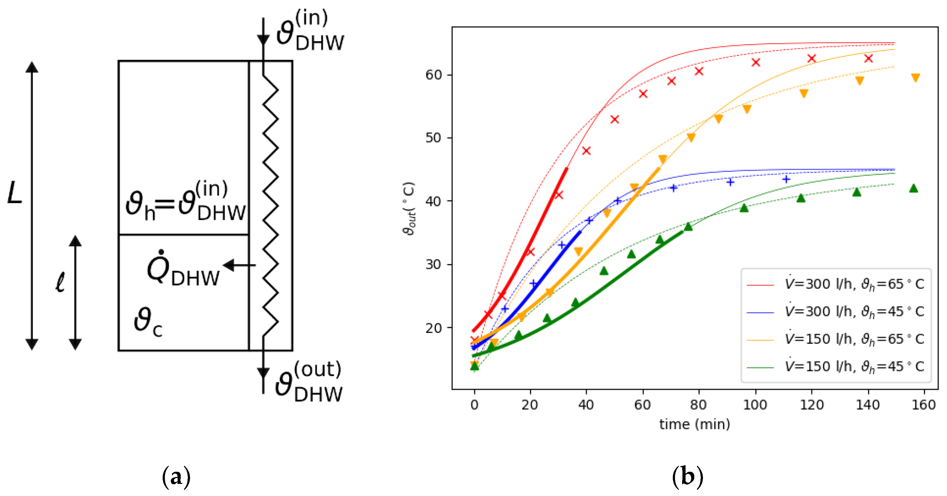
3.1. Simulation Models

Simulation studies were carried out for both the novel system and the reference system without RPW-HEX. The following performance indicators were computed to calculate the annual efficiencies: coefficient of performance related to the hot side of the HP for heating and cooling: COPh, coefficient of performance related to the hot side of the HP for DHW: COPDHW and RPW-HEX utilization factor: εRPW. The latter is the ratio of energy transferred to the RPW-HEX compared to the total energy on the hot side of the HP. The simulations were carried out in the Dymola/Modelica modelling environment using ThermoCycle library components [21]. Additionally, models for the RPW-HEX, the outdoor unit and the four-way valve were developed in-house [22,23]. Thermodynamic properties were taken from the CoolProp library [24]. A detailed description of the system model can also be found in [13,14]. The performance indicators were derived from the dynamic simulation when the system is in steady-state or when the SoC reached 50% for heating and cooling, respectively. Defrosting operation was neglected, and electric power consumption for COP calculations solely reflects the consumption of the compressor and the fan of the outdoor unit. All HP geometry/component design parameters, efficiencies and heat transfer coefficients were taken from design sheets or calculated from well-established equations and were later experimentally validated with measurements of the prototype air source HP used in the H2020 project HYBUILD [16] without RPW-HEX. Measured COPs of the HP without RPW-HEX for heating were 3.0, 4.3, 5.3 and 7.1 for ambient temperatures of −7, 2, 7, and 12 °C, inlet water temperatures to the heating system of 43, 37, 33, and 28 °C, and part load ratios of 88%, 54%, 35% and 15%, respectively. More information about the HP performance can be found in [15].

3.2. Annual Energy Efficiency Calculations

A quasi-static approach with rule-based control strategy (see Section 2.2) was used to estimate the annual energy demand of the systems. On an hourly basis, the energy consumption of the HP was calculated for each case for the system with and without RPW-HEX with the aid of performance maps generated with the dynamic simulations (see Section 3.1). The charge of the RPW-HEX and the decentralized DHW-storages were constantly updated and the building itself was considered as a storage to monitor hours when heating or cooling energy could not be provided (e.g., if hot water was generated during this hour). In this case, the increasing heating and cooling demand was covered in the hours to come. The thermal losses of the RPW-HEX and the DHW storage were calculated considering free convective and radiation losses to the surroundings. They reduced the charge of the storage devices every hour. As the return temperature of the DHW storage devices is a crucial value to calculate the performance of operating mode (c), an analytical model, based on a moving boundary in a perfect thermocline storage, was developed to calculate the contribution of condenser and the RPW-HEX for DHW generation in operating mode (c). The detailed DHW storage model, the method to calculate the time span for charging the DHW storage systems, and the importance of the return temperature to the performance of the system are discussed in Appendix A. The annual calculations were carried out on a standard PC using Python software.

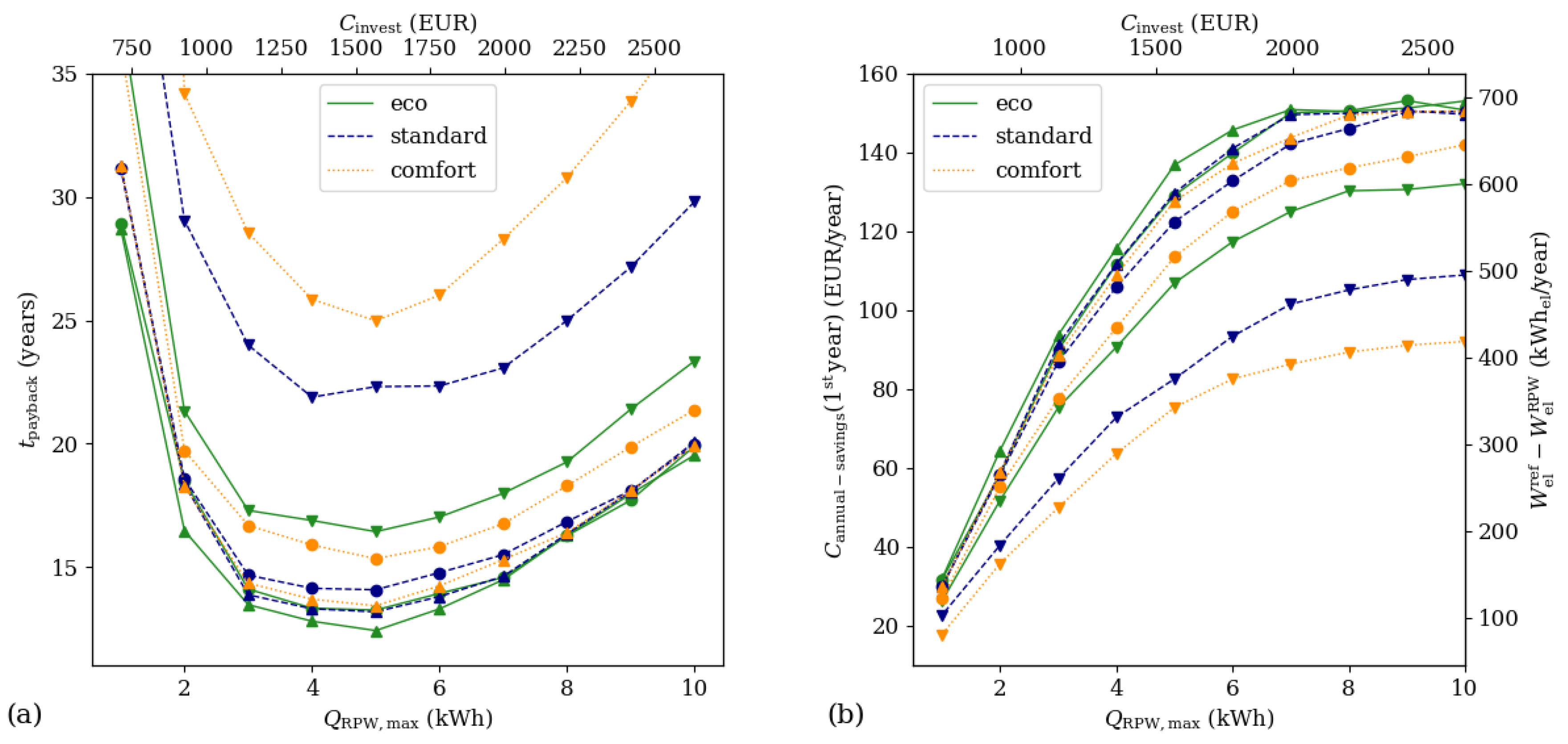
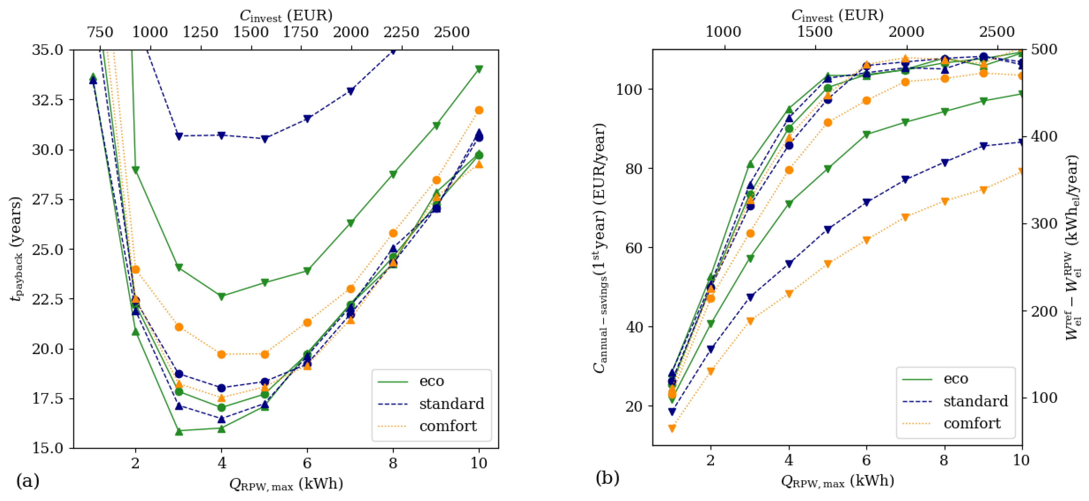
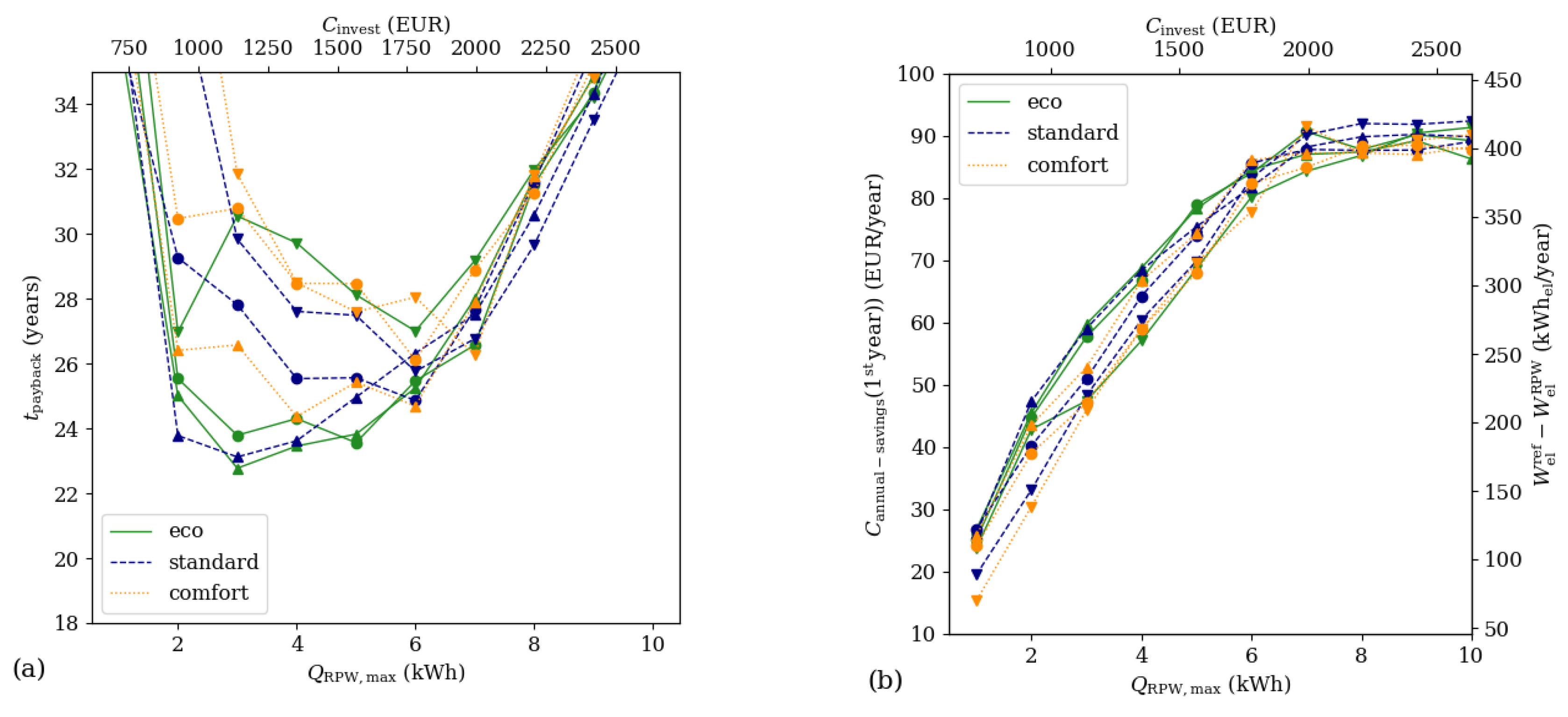
3.3. Parameter Variations

For each case, the storage capacity of the RPW-HEX was varied between 1 and 10 kWh. In addition, three different storage sizes of the DHW storage systems were considered, a small storage system with 140 L, a medium storage system with 210 L and a large storage system with 280 L volume. Besides the three storage sizes, three different charging modes for the DHW storage devices were defined and varied, namely:
  • eco-mode: charging starts if hot water (in a perfect thermocline) is below 40 L and stops at 90 L
  • standard-mode: DHW generation is initiated if hot water is below 55 L and stops at 105 L
  • comfort-mode: charging starts if hot water is below 70 L and stops at 120 L

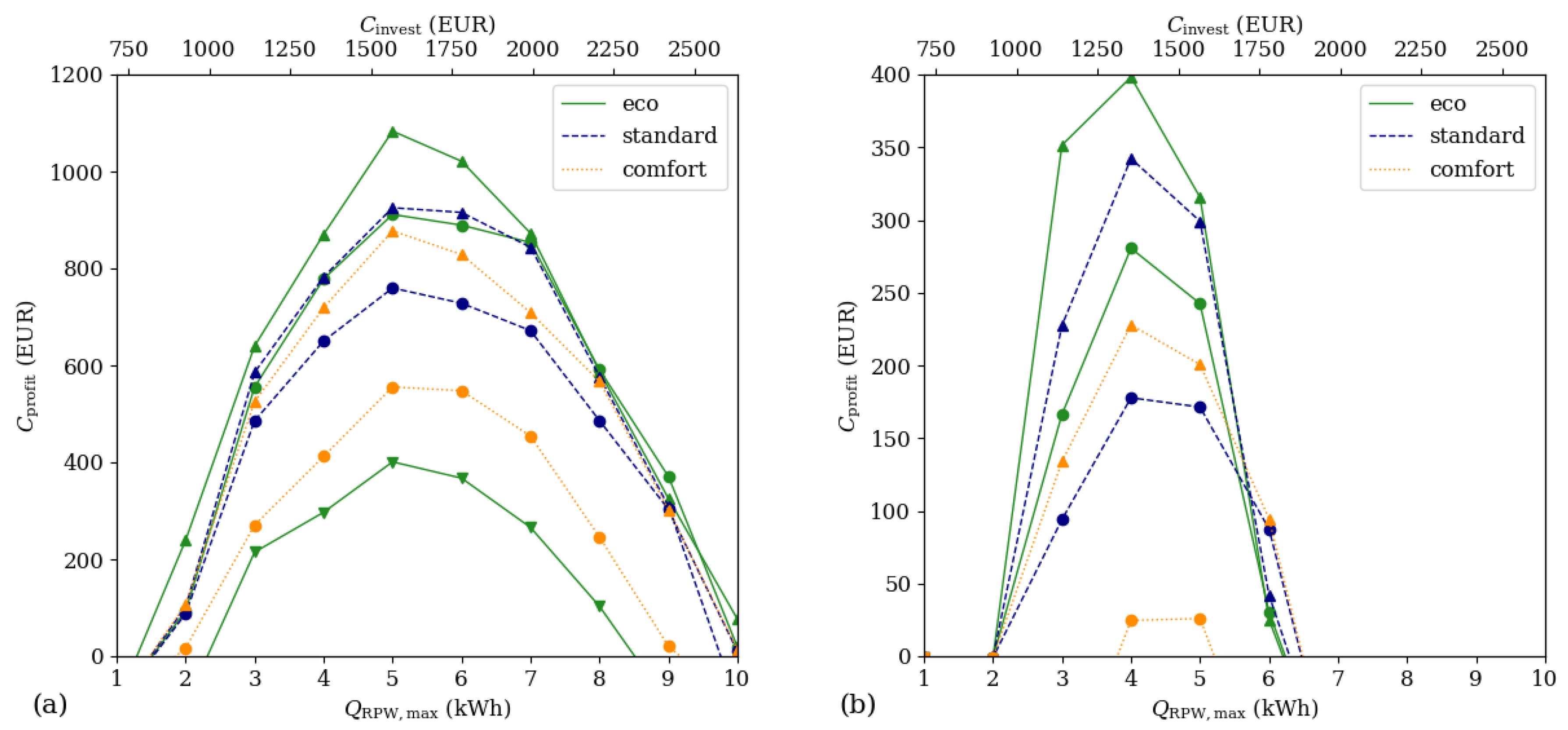
3.4. Economic Performance Indicators

The following performance indicators were evaluated for the three cases: investment costs, operating costs, payback time and profit after a lifetime of 20 years. Since the reference system for the proposed system is simply the proposed HP without the RPW-HEX, solely the additional costs to install the RPW-HEX to the HP were considered for the investment costs. They consist of the costs for the RPW-HEX including the insulation, the additional three-way valve and the piping needed for the integration in the HP cycle. All three costs can be separated in fixed and variable costs:
C invest = C invest , fix + c ˜ invest , var × Q RPW , max ,
where QRPW,max is the maximum storage capacity of the RPW-HEX. The fixed and variable costs were estimated after manufacturing a first version of the RPW-HEX for [25]. The following costs and properties were taken into account for a series production: 5.00 EUR/kg for PCM, 4.55 EUR/kg for aluminum, 6.00 EUR/m2 for mineral wool (10 cm thickness), a latent phase change energy of the PCM of 250 kJ/kg, a specific heat capacity of 2.00 kJkg−1K−1 for the PCM and 0.900 kJkg−1K−1 for aluminum, a PCM/aluminum ratio of 1:2.44 and a temperature difference of 10 K between the charging and discharging of the RPW-HEX during operation. The so-calculated fixed and variable costs for (1) are summarized in Table 2. Please note that the costs of the insulation do not correlate linearly with the storage capacity as the surface does not linear dependent on the volume. Nevertheless, for the sake of simplicity and the comparatively small share of the insulation material to the total costs, a linear dependency was also used for the costs of the insulation material.
As the maintenance costs of the RPW-HEX are included in the service costs incurred anyway, solely the differences in electric energy consumption were the basis for calculating the operating costs. The payback time tpayback was calculated as the time when the net present value becomes equal to the investment costs:
C i n v e s t   = t p = 1 N ( t p a y b a c k ) ( W e l r e f W e l R P W ) × c ˜ e l ( t p ) ( 1 + i ) t p ,
where the electric energy price/kWhel c ˜ el was assumed to be 0.22 EUR/kWh at the time of the investment (average energy price per kWh for households in the Euro area in 2018) with an increase of 0.006 EUR/year [26]. The discount rate i per time period tp was correlated with a fixed rate of 2 %/year and N is the number of periods at the payback time. Please note that waste disposal costs and profits from recycling were not considered. Using a standard Newton-solver, the payback time tpayback was calculated numerically from (2).
The annual cost savings are calculated from the difference between the annual electric energy consumption with and without the RPW-HEX ( W el ref , W el RPW ) and the electric energy price/kWhel ( c ˜ el ) in the year of operation t:
C annual   savings ( t ) = ( W el ref W el RPW ) × c ˜ el ( t ) .
The economic profit Cprofit after tlifetime years follows from:
C p r o f i t   = ( c e i l ( t p a y b a c k ) t p a y b a c k ) × C a n n u a l   s a v i n g s ( f l o o r ( t p a y b a c k ) ) + t = c e i l ( t p a y b a c k ) t l i f e t i m e C a n n u a l   s a v i n g s ( t ) .
Recent investigations with a PCM suitable for the proposed concept (RT64HC) did not show relevant degradation up to 8000 cycles [27]. This would imply an operating time of the proposed system of about 20 years. Therefore, no degradation effects of the PCM were considered in the calculations.

4. Results and Discussion

The economic performance indicators for Cases #1 to #3 were calculated for different RPW-HEX storage sizes, DHW storages sizes, and DHW storage charging strategies (operating modes).
The minimum payback time for Case #1, a passive house located in Helsinki, was found to be 12.4 years for an RPW-HEX storage size of 5 kWh operating in eco-mode with large DHW storage devices (Figure 2a). Interestingly enough, for all other parameter variations, the minimum payback time was also found for around the same RPW-HEX storage size of 5 kWh. For the parameter variation with the shortest payback time (RPW-HEX storage size of 5 kWh), the annual energy savings (Figure 2b) are 622 kWhel/year and the minimum cost savings are 137 EUR/year (calculated with the electric energy price in the first year of operation). Generally, it can be observed that the annual energy saving per year increases with RPW-HEX storage size until 5–6 kWh.
After that, the increase in energy savings becomes significantly smaller (and the payback time starts to increase, see Figure 2a). Therefore, it makes no sense to increase the RPW-HEX storage size beyond this point. For a system operating in standard-mode with medium DHW storage devices, the payback time is still 14.1 years and annual savings are 557 kWhel/year or at least 122 EUR/year, respectively. For small DHW storage devices (140 L) operating in standard- or comfort-mode, the payback time is always more than 20 years.
The reason for this strong dependence on the DHW storage device size, which is a characteristic for the system, arises due to the considerably lower return temperature of water from a large DHW storage device. In operating mode (c)—energy efficient DHW generation—the HP condenser delivers a significant amount of energy to the DHW storage devices as long as the condensing temperature does not exceed the condensing temperature during heating operation (see also different contributions to QDHWc in Figure 6). This contribution from the condenser is highly appreciated from an energetic point of view. If the water return temperature increases and the condensing temperature becomes higher in operating mode (c) than it is during heating, the controller turns the HP off and solely the energy discharged from the RPW-HEX is used for DHW generation. This control rule was defined because it is better to discharge the RPW-HEX (which was previously charged with a “heating COP”) than to run the HP with a COP higher than the “heating COP”.
Due to this dependence on the water return temperature from the DHW storage devices, it is also more important for small DHW storages to be operated in eco-mode which guarantees these low return temperatures. Furthermore, if the RPW-HEX is fully charged but no DHW is needed, the RPW-HEX can still be discharged by charging the DHW storage beyond the upper limit. Therefore, more energy can be transferred to the DHW whilst the RPW-HEX storage capacity stays the same during operation with large DHW storage devices.
For Case #2, a low energy building located in Strasbourg, the minimum payback times for most of the parameter variations were found for an RPW-HEX storage size of 4 kWh (Figure 3a). However, the absolute minimum was found at 3 kWh, large DHW storage devices and eco-mode. In this case, the payback time is 15.9 years. The energy and cost savings are 369 kWh/year and at least 81.1 EUR/year, respectively. The general behavior of payback time and savings per year is similar to Case #1, but the average minimum payback time is found for an RPW-HEX storage size of around 4 kWh, which is 1 kWh lower than the optimal size in Case #1. This fact is also reflected in the profits after 20 years for Cases #1 and #2 (Figure 4).
One finds maxima around RPW-HEX storage sizes of 5 to 7 kWh for Case #1 and maxima around 4 to 5 kWh for Case #2. The maximum profits are gained for Case #1 with large DHW storages, an RPW-HEX storage size of 5 kWh and operation in eco-mode. In this case, the profit is 1083 EUR after 20 years. For Case #2, the maximum profit was also gained for the large DHW storage devices operating in eco-mode, but with an RPW-HEX storage size of 4 kWh. The maximum profit in this case is 398 EUR after 20 years.
For Case #3, the refurbished building located in Athens, no scenarios exist where the payback times become less than 20 years (Figure 5a). Furthermore, the differences between eco-, standard- and comfort-charging modes is not as pronounced as in Case #1 and Case #2. The reason for this is that the share of the energy provided by the condenser for DHW generation during operating mode (c) is smaller than in the other two cases (compare also Case #1 and #3 in Figure 6). Hence, the dependence on the water return temperature and therefore on the storage size is not as strong as for the other cases.
Table 3 gives an overview of the energetic and economic performances of a 5 kWh RPW-HEX operating in standard-mode with medium DHW storage devices.
Although the relative energy savings are the highest for Case #3 (up to 5% of total energy savings per year and up to 25% of energy savings for DHW per year in Table 3) compared to the other two cases, the absolute cost savings or electric energy savings are smaller compared to Case #1 and #2. This can be explained by having a closer look at the daily DHW consumption for Case #1 and #3 in Figure 6.
In Case #1, 7.75 families (apartments) are supplied with domestic hot water (45.3 kWhth/day), whereas in Case #3, only 1.75 families (apartments) are supplied with domestic hot water (10.2 kWhth/day). Remember that the number of apartments was calculated considering that the HP (same design for all case studies and parameters) is able to provide the maximum heating or cooling demand of the building. Accordingly, the DHW consumption for each building results from the calculated number of apartments. In Case #3 (Figure 6b), the energy gained from heating operation (a) with charging the RPW-HEX is most of the time more than enough to cover the entire daily DHW demand during the winter season (which is depicted as a dotted line in Figure 6b). Therefore, the HP often switches to operating mode (e)—heating without charging the RPW-HEX—simply because the RPW-HEX is already fully charged and cannot be discharged to the likewise fully charged DHW storage devices.
In contrast to this, the DHW demand in Case #1 can never be covered entirely by energy efficient DHW operating mode (c), and therefore, the RPW-HEX can always be discharged to the DHW storage devices.
In other words, the number of charging/discharging cycles are higher in Case #1 than in Case #3, and therefore, the daily heat transfer from the RPW-HEX to the DHW storages is higher in absolute numbers in Case #1 (15.7 kWh/day) than in Case #3 (6.78 kWh/day), whilst the relative daily DHW covering ratio is higher in Case #3 (66.3%) than in Case #1 (34.7%). As the savings in operating costs are directly connected to the absolute savings in electric energy, the cost savings for Case #1 are higher compared to Case #3.

5. Conclusions and Outlook

This work presents a techno-economic analysis of the integration of a Refrigerant-PCM-Water heat exchanger (RPW-HEX) in the hot gas section of an R32 air source HP for heating, cooling and DHW generation operated in three different building types located in different climatic zones. The analysis was carried out to identify the optimal RPW-HEX storage size considering hourly based operation for a whole year, a rule-based control strategy and different operating modes. The lowest payback time of 12.4 years, the highest energy savings per year of 622 kWhel, and the highest profits after 20 years of 1083 EUR were found for Case #1, a passive house located in Helsinki with 7.75 standard apartments—operation in eco-mode with 8 large (280 L) DHW storage devices. It turns out that for buildings with medium and large DHW storage devices, the selection of the DHW charging mode (eco, standard or comfort) does not produce an as significant difference in the energetic and economic system performance as for buildings with small DHW storage devices. Thus, operation in the eco-(charging) mode is critical for small DHW storage devices. The results indicate further potential for significant improvements through the interaction with PV if feeding generated electric energy to the grid is less beneficial than storing the energy on site. Such systems rely on DHW storage with a comparatively high volume (high investment costs) in order to store PV generated thermal energy during day time in summer. The integration of an RPW-HEX would not only reduce the electric energy needed for DHW generation (and therefore PV size) but would also add an extra benefit to the installed DHW storage, making effective use of this storage in winter, i.e., in times of the year when the available storage capacity is only partially used by PV.
The results of this work indicate that, although there is significant potential for energy savings in a refurbishment building in a hot climate, from the economic point of view, the proposed system is better suited for a low-energy building in average- and a passive house in cold climates considering an average European electricity price of 0.22 EUR/kWh at the time of installation and a discount rate of 2%. The first experimental validations of the proposed system with a first RPW-HEX prototype have already successfully been carried out and are presented in [25].

Author Contributions

Conceptualization, J.E.; methodology, J.E. and K.M.; software, J.E.; validation, K.M., F.H., W.P. and J.E.; formal analysis, J.E., K.M., T.B., G.Z., L.F.C.; investigation, J.E., K.M. and F.H.; resources, M.W., A.S., B.N., W.P.; data curation, J.E., K.M. and F.H.; writing—original draft preparation, J.E.; writing—review and editing, all authors; visualization, J.E.; supervision, J.E.; project administration, J.E.; funding acquisition, J.E., T.B., L.F.C., A.S., M.W., W.P. All authors have read and agreed to the published version of the manuscript.

Funding

This project has received funding from the European Union’s Horizon 2020 research and innovation programme under grant agreement No 768824 (HYBUILD). This work is partially supported by ICREA under the ICREA Academia programme.

Acknowledgments

The authors thank C. Köfinger, M. Lauermann, and A. Zottl for critical discussion. Furthermore, we thank A. Bras and S. Hauer for their assistance in generating the data of the different buildings. The authors at the University of Lleida would like to thank the Catalan Government for the quality accreditation given to their research group (2017 SGR 1537). GREiA is certified agent TECNIO in the category of technology developers from the Government of Catalonia.

Conflicts of Interest

The authors declare no conflict of interest. The funders had no role in the design of the study; in the collection, analyses, or interpretation of data; in the writing of the manuscript, or in the decision to publish the results.

Nomenclature

Symbols
a,b,d,k1Constants of the moving boundary model for the DHW storage (W, -, J−1, J)
ADHWGround area of the DHW storage (m2)
c ˜ Specific costs (EUR/kWhel)
cp,wSpecific heat capacity of water (Jkg−1K−1)
CCosts (EUR)
COPCoefficient of Performance
LHeight of the DHW storage (in the moving boundary model) (m)
m ˙ Mass flow rate (kg s−1)
QThermal energy (J or kWh)
Q ˙ Heat flow rate (W)
tTime (years)
wWidth of the heat transfer cross-section of the DHW storage
WelElectric energy (kWh)
εRPWRatio of thermal energy that can be transferred to the RPW-HEX
Length of the cold section in the moving boundary model of the DHW storage (m)
ϑTemperature (°C)
τTime span of the DHW charging process(s)
Abbreviations
cCold
conCondenser
DHWDomestic Hot Water
HPHeat Pump
mscMinimum speed of compressor
PCMPhase Change Material
RPW-HEXRefrigerant-PCM-water heat exchanger
RPW,PContribution of PCM in RPW-HEX
RPW,RContribution of refrigerant in PCM
REFReference system without RPW-HEX
SoCState of Charge
spSet-point
wWater

Appendix A

The conservation of energy during the energy efficient DHW generation operation mode (c)—cf. Figure 1c—in the process water cycle is given by:
Q ˙ con +   Q ˙ RPW , P + Q ˙ RPW , R Q ˙ DHW =   0 ,
where Q ˙ con is the heat transferred from the refrigerant to the water by the condenser, Q ˙ RPW , P is the heat transferred by discharging the PCM in the RPW-HEX to the water, Q ˙ RPW , R is the heat transferred from the refrigerant in the RPW-HEX directly to the water and Q ˙ DHW is the heat transferred to the DHW storages. The latter can be calculated by the in- and outlet temperature of the water:
Q ˙ DHW =   m ˙ w c p , w ( ϑ DHW ( in ) ϑ DHW ( out ) ) ,
and if the HP is running, the contribution of the condenser can be described with:
Q ˙ con =   m ˙ w c p , w ( ϑ sp ϑ DHW ( out ) ) ,
where ϑsp is the set-point temperature for heating which is also used for DHW generation in operating mode (c) to preheat the water at a high COP. The sensible energy of the hot gas transferred through the RPW-HEX can be calculated from the efficiency of the RPW-HEX
Q ˙ RPW , R =   Q ˙ con ε RPW 1 ε RPW ,
where εRPW is the fraction of the total heat at the hot side of the HP that can be transferred to the RPW-HEX and has to be taken from experiments or simulations (cf. [15]). The heat transfer rate needed to be transferred from the PCM to the DHW ΔQRPW,P is the heat that cannot be provided by the refrigerant of the HP. It can be calculated from (A1) and the energy extracted from the RPW-HEX after the time τ is:
Δ Q RPW , P =   0 τ ( Q ˙ DHW Q ˙ con Q ˙ RPW , R ) d t ,
To calculate the energies (A2–A5) the change in time of the outlet temperature of the DHW storage ( ϑ DHW ( out ) ) is crucial, because this temperature strongly influences the contribution of the HP to the heat transferred to the DHW storages. If ϑ DHW ( out ) is significantly smaller than the set point temperature ϑsp, the HP can operate at a high part load (since the volume flow rate is fixed) and therefore can provide a high share of thermal energy to the DHW charging process. If ϑ DHW ( out ) is close to the condensing temperature or even higher, the HP will turn off, and all the energy must be provided by the PCM. Hence, ϑ DHW ( out ) has a high impact to the RPW-HEX storage capacity needed for providing a certain amount of thermal energy for the DHW storages.
In the present work, we use a moving boundary approach to describe the thermocline behavior of the DHW storages to find an analytic solution for A5. Figure A1a shows the principle of the approach.
Figure A1. (a) Scheme of the moving boundary approach. (b) Fitting (A12) to experimental data of a charging process of a 140 L enerboxx®® storage (storage used in [28]) for different temperatures and volume flow rates. The solid lines in (b) represent the moving boundary approach calculated from (A12), the dotted line represent a lumped parameter approach (not described) and the markers denote measured temperatures from the experiment.
Applsci 10 07873 g0a1
The storage consists of an upper volume at hot temperature (ϑh), which is always heated to a temperature corresponding to the constant inlet temperature and a lower volume at cold temperature (ϑc), whose temperature corresponds to the fresh water temperature. Both volumes are separated by a moving boundary ( ) which depends directly on the stored energy:
= L Q DHW A DHW   ρ w   c p , w   ( ϑ DHW ( in ) ϑ c ) ,
where ADHW is the ground area of the DHW storage, L is the height of the DHW storage, ρw is the density and cp,w is the specific heat capacity of water. Note that with the aid of the three-way valve (component M in Figure 1), the inlet temperature to the DHW storage ϑ DHW ( in ) is held constant at a fixed temperature by mixing the process water leaving the RPW-HEX with the water leaving the condenser in the real machine. Hence it can be assumed as constant.
The maximum energy can be stored if the entire storage is charged to ϑh ( = 0) and the storage is empty if the entire storage has a temperature of ϑc ( = L). Heating of the DHW storage only takes place in the cold region of the storage. Using an NTU description for a constant wall temperature (ϑc) one finds for the heat transfer to the DHW storage:
Q ˙ DHW =   m ˙ w c p , w ( ϑ DHW ( in ) ϑ c )   ( 1 e α   w m ˙ w   c p , w   ) ,
where w is the width of the storage (i.e., the heat transfer cross-section between the cold fresh water and the process water coming from the HP is w ), α is the heat transfer coefficient between the cold fresh water cell and the process water, and m ˙ w is the mass flow rate of the process water. A turbulent flow in the storage is considered, and therefore, the heat transfer coefficient α is assumed to change with m ˙ w according to:
α =   α nom ( m ˙ w m ˙ w , nom   ) 0.8 ,
where m ˙ w , nom is the nominal mass flow rate calculated at a volume flow fate of 300 l/h and the factor 0.8 follows from the Colburn equation.
Inserting (A6) in (A8), one finds, after carrying out algebraic transformations, a differential equation that can be solved analytically to:
Q DHW =   0 t Q ˙ DHW d t = ln ( e d   ( k 1 a t ) + b ) d ,
where a, b and d are constants that have been introduced for better handling of the equations:
a =   m ˙ w c p , w ( ϑ DHW ( in ) ϑ c ) b =   e α   w m ˙ w   c p , w   L     d   =   α   w m ˙ w   c p , w 2   A DHW   ρ w   ( ϑ DHW ( in ) ϑ c ) ,
and k1 can be determined by solving the initial value problem at t = 0:
k 1 =   ln ( e Q DHW 0   d   b ) d  
Using (A6) and (A9) in (A2) gives an equation for the outlet temperature of the DHW storage:
ϑ DHW ( out ) =   ϑ DHW ( in )   ( ϑ DHW ( in ) ϑ c )   ( 1 b e d   ( k 1 a t ) + b ) .
Figure A1b shows (A12) fitted with αnom = 484 Wm−2 K−1 to measured data from a charging experiment with an enerboxx®® storage. Furthermore, the presented approach is compared to a lumped parameter approach, where a perfectly mixed water volume was assumed. The behavior of the outlet temperature in the region of interest (low temperatures indicated by the strong solid line of the moving boundary approach in Figure A1b) can be reproduced significantly better with the presented approach. Nevertheless, the moving boundary method will always underestimate the real temperature whereas the lumped parameter approach will always overestimate the real temperature.
Inserting (A12) in (A2) gives an equation for the heat transfer rate to the DHW storage dependent on time:
Q ˙ DHW ( t ) =   a   ( 1 b e d   ( k 1 a t ) + b )
The heat transfer at the condenser is limited by two constraints. Firstly, by the set point temperature ϑsp (outlet temperature of the water after the condenser) and secondly by the minimum heat transfer that is provided at the minimal rotational speed of the compressor Q ˙ con , msc . The compressor turns off, once ϑ DHW , msc ( out ) at the minimum speed of the compressor is reached:
ϑ DHW , msc ( out ) = ϑ sp   Q ˙ con , msc m ˙ w c p , w
Inserting (A14) in (A12) and numerical rearrangement gives an equation for the time when the minimum rotational speed is reached:
τ msc = 1 a   ( k 1 ln ( b ) d ln ( ϑ DHW ( in ) ϑ c ϑ sp Q ˙ con , msc m ˙ w c p , w   ϑ c 1 ) d ) ,
With (A2), (A3) and the considerations discussed before, one finds an equation for the energy transferred over the condenser during operation mode (c) depending on the time t:
Q con ( t )   =   { 0 𝜏 min   <   0 Q DHW ( t ) Q DHW 0 m ˙ w c p , w ( ϑ DHW ( in ) ϑ sp )   t 0     t   <   𝜏 msc Q DHW ( 𝜏 min ) Q DHW 0 m ˙ w c p , w ( ϑ DHW ( in ) ϑ sp )   𝜏 msc 0     𝜏 msc     t
If τmsc from (A15) is negative as in the first case of (A16), the HP is always off because the outlet temperature of the DHW storage is already above ϑ DHW , msc ( out ) at the beginning (t = 0). Therefore no energy is transferred directly from the refrigerant to the process water (Qcon = 0, QRPW,R = 0) and all the energy for the storage has to be provided by the RPW-HEX. If the outlet temperature of the DHW storage is always below ϑ DHW , msc ( out ) , 0 ≤ t < τmsc, as in the second case of (A16) the HP is turned on all the time and the compressor is controlled to provide always as much energy as needed to reach the set-point ϑsp at the condenser water outlet. If the HP reaches its minimum power within the time of the operation 0 ≤ τmsct, the HP will be turned off at τmsc and the energy is then provided by the RPW-HEX, only.
The energy transferred from the refrigerant to the hot water over the RPW-HEX follows by integrating (A4) and finally the energy extracted from the stored energy in the RPW-HEX follows from integrating (A5) to:
Q RPW , P ( t ) =   Q DHW ( t ) Q DHW 0 Q con ( t ) 1 ε RPW
From (A9) one can calculate the time τDHW needed to charge the DHW storages to a certain energy set-point Q DHW sp (e.g., the upper limit) analytically:
τ D H W ( Q DHW sp ) = 1 a   d   ( d   k 1 ln ( e d Q DHW sp b ) )
Inserting τDHW from (A18) as t in (A17) gives finally the energy QRPW,P that has to be extracted from the RPW-HEX to charge the DHW-storage to this certain set-point Q DHW sp .
Figure A2 shows the contribution of the refrigerant and the PCM to the hot water generation in operating mode (c) over the time at a typical operation condition (ϑ = 0 °C, ϑsp = 43 °C, ϑc = 12 °C, ϑ DHW ( in ) = 60 °C, 210 L storage, standard-mode). Due to the increasing temperature of the water leaving the storage ϑ DHW , msc ( out ) (decreasing cf. Figure A1a), the heat transfer rate decreases with time (cf. Figure A2a). Additionally, due to the restriction of the fixed set-point for the HP (ϑsp = 43 °C), the heat provided by the condenser has to decrease. Hence, the HP reaches the minimum operation speed of the compressor at τmsc and the compressor turns off. Until the DHW storage is fully charged at τDHW, the remaining energy must be provided by the PCM. At the end of the charging process, about one third of the energy for providing DHW at 60 °C was taken from the HP operating with a heating COP and about two third of energy were taken from the energy stored in the RPW-HEX (which was also stored when the HP was operated in heating mode with a high COP (cf. Figure A2b).
Figure A2. (a) Calculated heat transfer rate to the decentralized DHW storages during the energy efficient DHW charging operating mode (c) for a storage at the lower charging limit in standard operating mode at t = 0. The heat transfer rate consists of contributions from the refrigerant via the condenser (green) and the RPW-HEX (blue) and of the contribution from the PCM and the aluminum in the RPW-HEX (orange). (b) shows the calculated total amount of energy transferred to the DHW storages during the charging process.
Applsci 10 07873 g0a2
The time τRPW to extract a certain amount of energy from the RPW-HEX can be calculated numerically, e.g., with a Newton-solver, by inserting (A9) in (A17). Note that this is only possible if the energy stored in the RPW-HEX is lower than the maximum transferable energy from the RPW-HEX to the DHW storage which is limited by the DHW storage size or the defined maximum charging level of the DHW storage, respectively. If this is the case, the charging time can be calculated with (A18) and the remaining difference of energy remains in the RPW-HEX after the DHW-charging operation process.

References

  1. IEA. Heat Pumps, IEA, Paris. 2020. Available online: https://www.iea.org/reports/heat-pumps (accessed on 8 September 2020).
  2. Pardiñas, A.A.; Alonso, M.J.; Diz, R.; Kvalsvik, K.H.; Fernández-Seara, J. State-of-the-art for the use of phase-change materials in tanks coupled with heat pumps. Energy Build. 2017, 140, 28–41. [Google Scholar] [CrossRef] [Green Version]
  3. Li, Y.; Nord, N.; Xiao, Q.; Tereshchenko, T. Building heating applications with phase change material: A comprehensive review. J. Energy Storage 2020, 31, 101634. [Google Scholar] [CrossRef]
  4. Kapsalis, V.; Karamanis, D. Solar thermal energy storage and heat pumps with phase change materials. Appl. Therm. Eng. 2016, 99, 1212–1224. [Google Scholar] [CrossRef]
  5. Zou, D.; Ma, X.; Liu, X.; Zheng, P.; Cai, B.; Huang, J.; Guo, J.; Liu, M. Experimental research of an air-source heat pump water heater using water-PCM for heat storage. Appl. Energy 2017, 206, 784–792. [Google Scholar] [CrossRef]
  6. Song, M.; Deng, S.; Dang, C.; Mao, N.; Wang, Z. Review on improvement for air source heat pump units during frosting and defrosting. Appl. Energy 2018, 211, 1150–1170. [Google Scholar] [CrossRef]
  7. Spitler, J.; Bernier, M. Ground-source heat pump systems: The first century and beyond. HVAC R Res. 2011, 17, 891–894. [Google Scholar]
  8. Cabeza, L.F.; Castell, A.; Barreneche, C.; de Gracia, A.; Fernández, A.I. Materials used as PCM in thermal energy storage in buildings: A review. Renew. Sustain. Energy Rev. 2011, 15, 1675–1695. [Google Scholar] [CrossRef]
  9. Ravotti, R.; Fellmann, O.; Lardon, N.; Fischer, L.J.; Stamatiou, A.; Worlitschek, J. Synthesis and Investigation of Thermal Properties of Highly Pure Carboxylic Fatty Esters to Be Used as PCM. Appl. Sci. 2018, 8, 1069. [Google Scholar] [CrossRef] [Green Version]
  10. Du, K.; Calautit, J.; Wang, Z.; Wu, Y.; Liu, H. A review of the applications of phase change materials in cooling, heating and power generation in different temperature ranges. Appl. Energy 2018, 220, 242–273. [Google Scholar] [CrossRef]
  11. Baxter, V.D. Comparison of Field Performance of a High-Efficiency Heat Pump with and without a Desuperheater Water Heater. ASHRAE Trans. 1984, 90, 180. [Google Scholar]
  12. Lee, A.H.W.; Jones, J.W. Thermal performance of a residential desuperheater/water heater system. Energy Convers. Manag. 1996, 37, 389–397. [Google Scholar] [CrossRef]
  13. Heinz, A.; Lerch, W.; Heimrath, R. Heat pump condenser and desuperheater integrated into a storage tank: Model development and comparison with measurements. Appl. Therm. Eng. 2016, 102, 465–475. [Google Scholar] [CrossRef]
  14. Shao, S.; Shi, W.; Li, X.; Ma, J. A new inverter heat pump operated all year round with domestic hot water. Energy Convers. Manag. 2004, 45, 2255–2268. [Google Scholar] [CrossRef]
  15. Emhofer, J.; Barz, T.; Marx, K.; Hochwallner, F.; Cabeza, L.F.; Zsembinszki, G.; Strehlow, A.; Nitsch, B.; Weiss, M. Integration of a compact two fluid PCM heat exchanger into the hot superheated section of an air source heat pump cycle for optimized DHW generation. In Proceedings of the 25th IIR International Congress of Refrigeration, Montreal, Canada, 24−30 August 2019. [Google Scholar]
  16. EN 14825:2018. Air Conditioners, Liquid Chilling Packages and Heat Pumps, with Electrically Driven Compressors, for Space Heating and Cooling—Testing and Rating at Part Load Conditions and Calculation of Seasonal Performance; British Standards Institution: London, UK, 2018. [Google Scholar]
  17. Barz, T.; Seliger, D.; Marx, K.; Sommer, A.; Walter, S.F.; Bock, H.G.; Körkel, S. State and state of charge estimation for a latent heat storage. Control Eng. Pract. 2018, 72, 151–166. [Google Scholar] [CrossRef]
  18. EN 16147:2017. Heat Pumps with Electrically Driven Compressors–Testing, Performance Rating and Requirements for Marking of Domestic Hot Water Units; British Standards Institution: London, UK, 2017. [Google Scholar]
  19. Hauer, S.; Judex, F.; Bres, A. BMG- Building Model Generator: Reducing the effort for thermal building simulation by automation. In Proceedings of the e-nova International Congress 2016, Pinkafeld, Austria, 24–25 November 2016; pp. 229–236. [Google Scholar]
  20. Bres, A.; Eder, K.; Hauer, S.; Judex, F. Case study of energy performance analyses on different scales. Energy Procedia 2015, 78, 1847–1852. [Google Scholar] [CrossRef] [Green Version]
  21. Quoilin, S.; Desideri, A.; Wronski, J.; Bell, I.; Lemort, V. ThermoCycle: A Modelica library for the simulation of thermodynamic systems. In Proceedings of the 10th International Modelica Conference 2014, Lund, Sweden, 10–12 March 2014. [Google Scholar]
  22. Emhofer, J.; Barz, T.; Palomba, V.; Frazzica, A.; Sergi, F.; Varvagiannis, S.; Karellas, S.; Oró, E.; Zsembinszki, G.; Cabeza, L.F. Deliverable D3.1 of the HYBUILD-Project: Modular Flow Sheet Simulation of the Hybrid (sub-)System. Available online: http://www.hybuild.eu/publications/deliverables/ (accessed on 8 September 2020).
  23. Frazzica, A.; Palomba, V.; Sergi, F.; Ferraro, M.; Cabeza, L.F.; Zsembinszki, G.; Oró, E.; Karellas, S.; Varvagiannis, S.; Emhofer, J.; et al. Dynamic Modelling of a Hybrid Solar Thermal/electric Energy Storage System for Application in Residential Buildings. In Proceedings of the 12th International Conference on Solar Energy for Buildings and Industry, Raperswil, Switzerland, 10–13 September 2018. [Google Scholar]
  24. Bell, I.H.; Wronski, J.; Quoilin, S.; Lemort, V. Pure and Pseudo-pure Fluid Thermophysical Property Evaluation and the Open-Source Thermophysical Property Library CoolProp. Ind. Eng. Chem. 2014, 53, 2498–2508. [Google Scholar] [CrossRef] [PubMed] [Green Version]
  25. Marx, K.; Emhofer, J.; Barz, T.; Krämer, J.; Cabeza, L.F.; Zsembinszki, G.; Strehlow, A.; Nitsch, B.; Wiesflecker, M.; Zitzenbacher, R.; et al. Dynamic Performance Tests of a Heat Pump Cycle Integrated Latent Heat Thermal Energy Storage for Optimized DHW Generation. Unpublished work. 2020. [Google Scholar]
  26. EUROSTAT, Electricity Price Statistics–Statistics Explained. Available online: https://ec.europa.eu/eurostat/statistics-explained/index.php/Electricity_price_statistics#Electricity_prices_for_household_consumers (accessed on 8 September 2020).
  27. Zsembinszki, G.; Fernández, A.G.; Cabeza, L.F. Selection of the Appropriate Phase Change Material for Two Innovative Compact Energy Storage Systems in Residential Buildings. Appl. Sci. 2020, 10, 2116. [Google Scholar] [CrossRef] [Green Version]
  28. HYBUILD Project, Innovative Compact Hybrid Storage Systems for Low Energy Buildings. Available online: http://www.hybuild.eu/ (accessed on 8 September 2020).
Figure 1. Concept of the proposed system for an example scenario with three apartments during: (a) heating operation, (b) cooling operation, (c) energy efficient domestic hot water (DHW) generation by discharging the RPW-HEX and (d) direct DHW generation. (S) Decentralized sensible DHW storage, (H) fan-coils suitable for heating and cooling, (C) condenser, (R) RPW-HEX, (W) four-way valve, (B) bypass expansion valve, (X) regular expansion valve, (F) fluid phase heat exchanger, (E) evaporator and fan, (P) compressor, (M) three-way valve. The temperatures indicated in (a,b,d) were taken from steady-states at a state of charge (SoC) of 50% for heating and cooling, respectively, whereas they were taken shortly after switching from mode (a) to (c) in (c). The ambient temperature ( ϑ ) was 0 °C in (a,c,d) and 35 °C in (b).
Applsci 10 07873 g001
Figure 2. Payback time (a) and savings per year (b) for Case #1 (passive house located in Helsinki). Markers “▼”, “●” and “▲” denote small (140 L), medium (210 L) and large (280 L) decentralized DHW storage devices.
Applsci 10 07873 g002
Figure 3. Payback time (a) and savings per year (b) for Case #2 (low-energy building located in Strasbourg). Markers “▼”, “●” and “▲” denote small (140 L), medium (210 L) and large (280 L) decentralized DHW storage devices. Please note that for the case with small decentralized storage devices operated in comfort mode, the payback time is higher than 35 years for all RPW-HEX storage sizes. Therefore, this case is not shown in (a).
Applsci 10 07873 g003
Figure 4. Profit after 20 years of operation for (a) Case #1 (passive house located in Helsinki) and (b) Case #2 (low energy building located in Strasbourg). Markers “▼”, “●” and “▲” denote small (140 L), medium (210 L) and large (280 L) decentralized DHW storage devices. Please note that for some cases, no profit can be made after 20 years of operation, so they are not shown in the figures.
Applsci 10 07873 g004
Figure 5. Payback time (a) and savings per year (b) for Case #3 (refurbished building located in Athens). Markers “▼”, “●” and “▲” denote small (140 L), medium (210 L) and large (280 L) decentralized DHW storage devices.
Applsci 10 07873 g005
Figure 6. Daily DHW consumption and provided energy for energy efficient DHW generation by operating mode (c) QDHW,c for (a) Case #1 and (b) Case #3 and variations from Table 3. The different colors mark the contribution from the condenser (“con”, green), from the refrigerant transferred via the RPW-HEX (“RPW-ref”, blue) and from the energy stored in the PCM-material/aluminum (“RPW-PCM”, orange). The dotted line marks the average DHW consumption and the dashed line mark the average contribution of DHW to the DHW consumption by operating mode (c).
Applsci 10 07873 g006
Table 1. Constraints of the case studies.
ConstraintCase #1
Passive House in Helsinki
Case #2
Low Energy Building in Strasbourg
Case #3
Refurbished Building in Athens
Apartments and total floor area per building7.75, 581 m25.25, 394 m21.75, 131 m2
Heating demand per year and m2 (kWh year−1 m−2)14.831.561.7
Maximum heating demand (kW)6.979.897.15
Maximum cooling demand (kW)10.89.6810.67
Daily DHW demand without losses (kWh)45.330.710.2
Annual heating demand (kWh)859812,4138096
Annual cooling demand (kWh)690353609401
Annual DHW demand without losses (kWh)16,53411,2003733
HP design load heating Pdesign,heating (kW)7.22 (at −22 °C)9.66 (at −10 °C)13.0 (at 2 °C)
HP design load cooling Pdesign,cooling (kW)10.843 (at 35 °C)10.843 (at 35 °C)10.843 (at 35 °C)
ϑwater,heating,distribution,in (°C)22–3524–4524–45
ϑwater,cooling,distribution,in (°C)7–11.57–11.5 7–11.5
Main purposemostly heatingheatingmostly cooling
Table 2. Constant and variable investment costs.
C i n v e s t , f i x   ( EUR ) c ˜ i n v e s t , v a r   ( EUR / kWh )
Manufacturing costs RPW-HEX500Aluminum 137.0
Three-way valve and additional piping20PCM61.7
Insulation (mineral wool)2.6
Total520 201.3
Table 3. Performance of systems with 5 kWh RPW-HEX and medium DHW storage devices working in standard-operation mode.
Case #1Case #2Case #3
Energy demand for heat-ing per year (RPW/REF)2990 kWhel/3972 kWhel/2231 kWhel/
2939 kWhel3918 kWhel2180 kWhel
Energy demand for cool-ing per year (RPW/REF)2000 kWhel/1692 kWhel/3520 kWhel/
2059 kWhel1753 kWhel3616 kWhel
Energy demand for DHW per year (RPW/REF)6086 kWhel/3713 kWhel/900 kWhel/
6634 kWhel4150 kWhel1191 kWhel
Energy savings for heating per year −51.2 kWhel (−1.74%)−55.5 kWhel (−1.42%)−50.5 kWhel (−2.32%)
Energy savings for cooling per year59.0 kWhel (2.86%)61.6 kWhel (3.51%)95.8 kWhel (2.65%)
Energy savings for DHW per year549 kWhel (8.27%)436 kWhel (10.5%)291 kWhel (24.4%)
Total energy savings per year557 kWhel (4.78%)442 kWhel (4.50%)336 kWhel (4.81%)
Investment costs1526 EUR1526 EUR1526 EUR
Payback time14.1 years18.3 years25.6 years
Minimum cost savings per year (based on first year) 122 EUR97.3 EUR74.0 EUR
Profit after 20 years760 EUR171 EUR-
Publisher’s Note: MDPI stays neutral with regard to jurisdictional claims in published maps and institutional affiliations.

