Analysis of the Cause and Mechanism of Hydraulic Gate Vibration during Flood Discharging from the Perspective of Structural Dynamics


Abstract
:1. Introduction
2. Prototype Test for the Vibration of the Hydraulic Gate
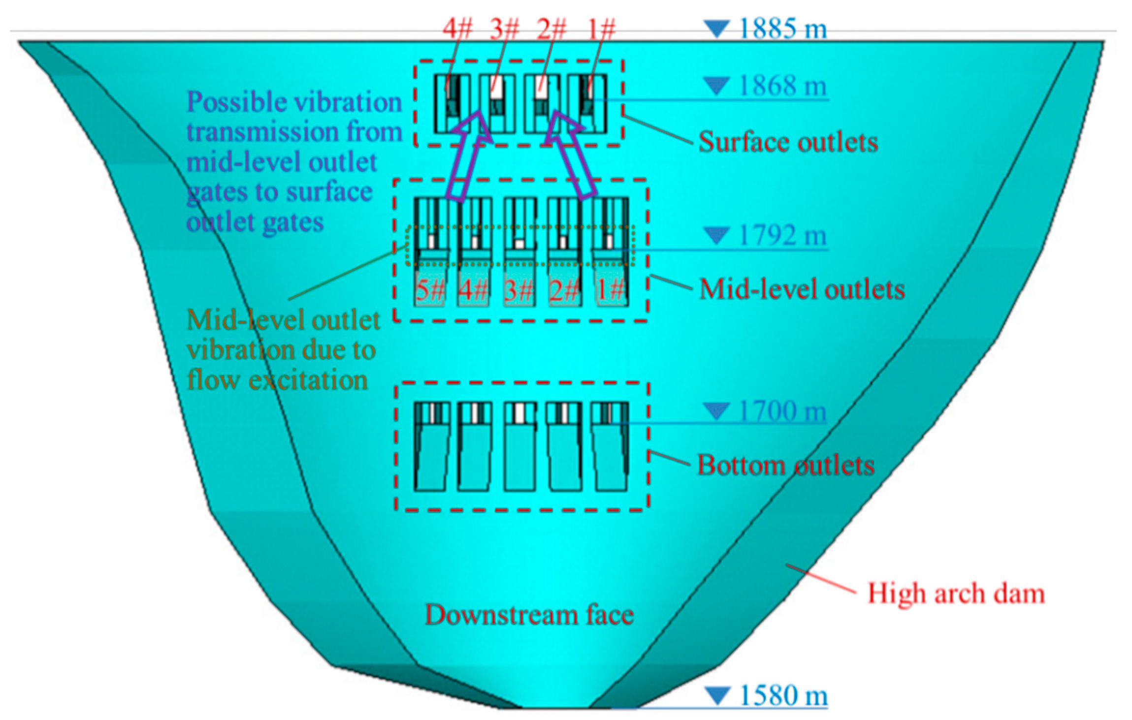
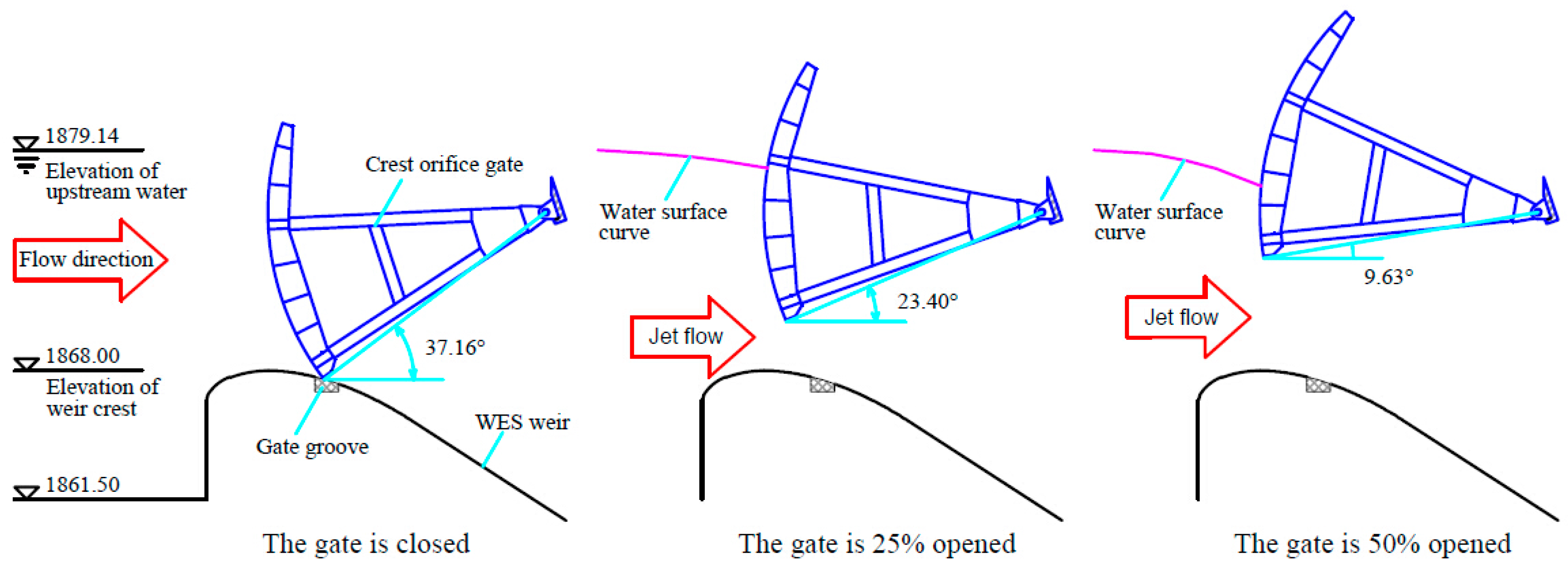
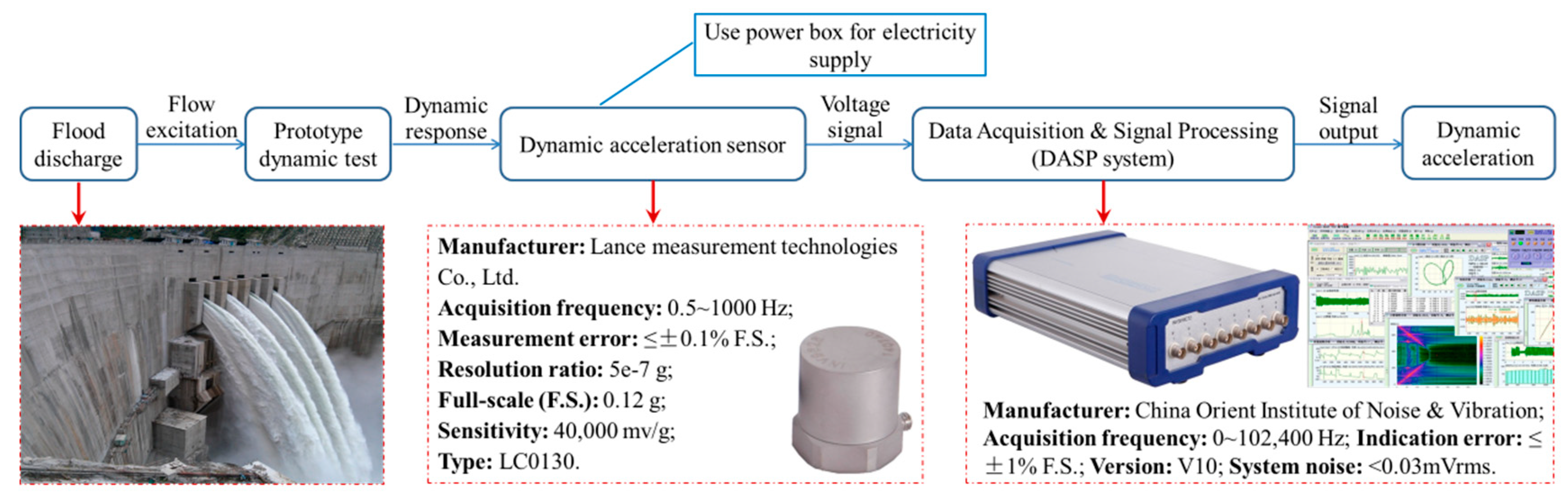
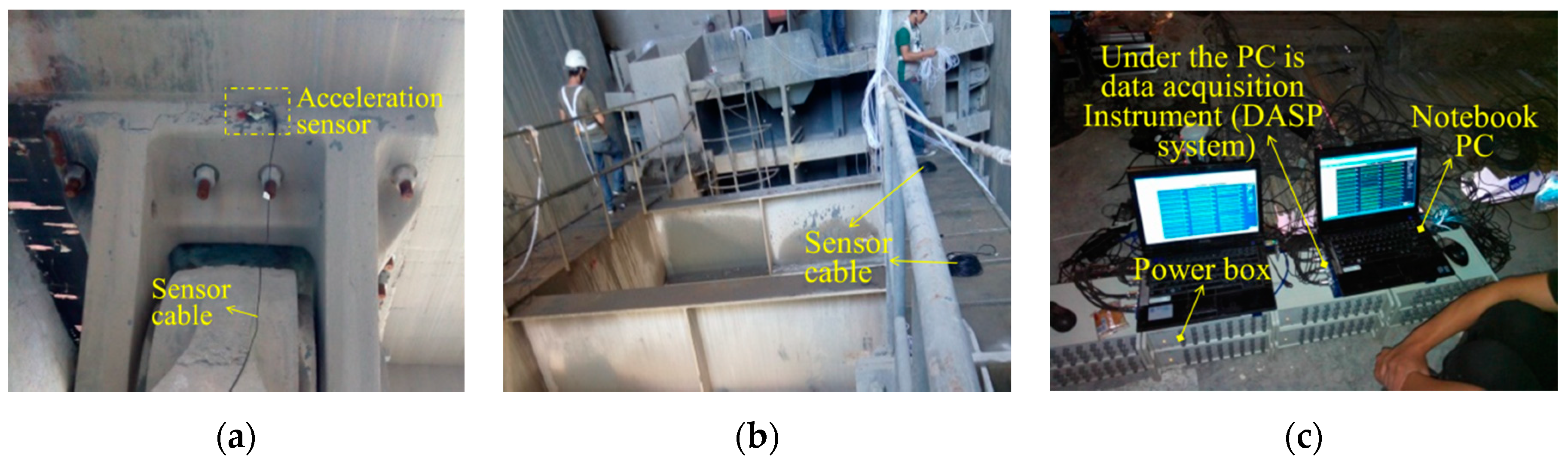
2.1. Basic Information for Jinping I Hydraulic Project and the Prototype Test
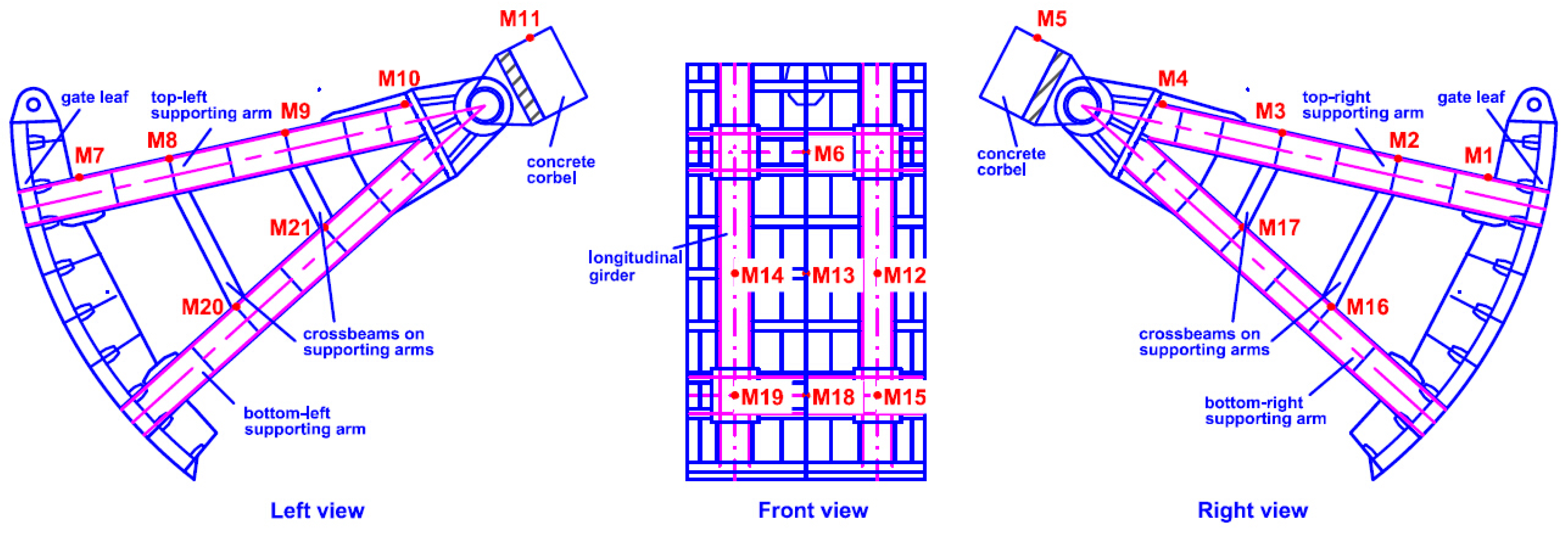
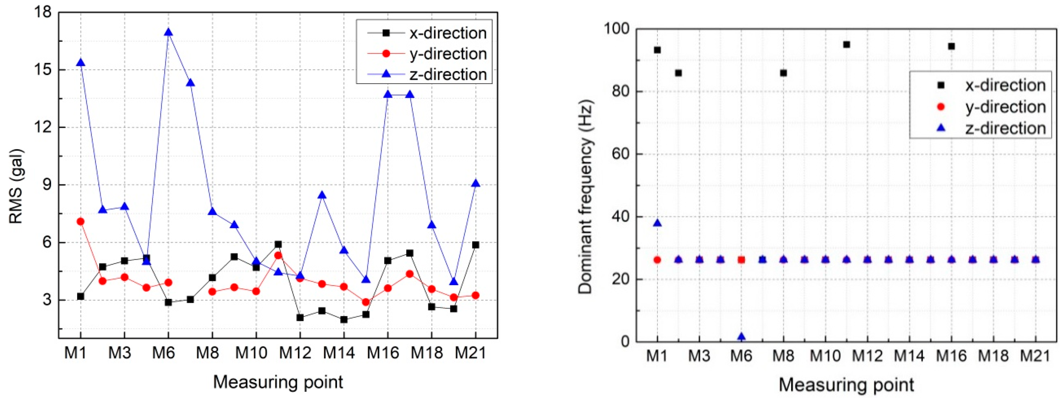
2.2. Vibration of the Mid-Level Outlet Radial Gate
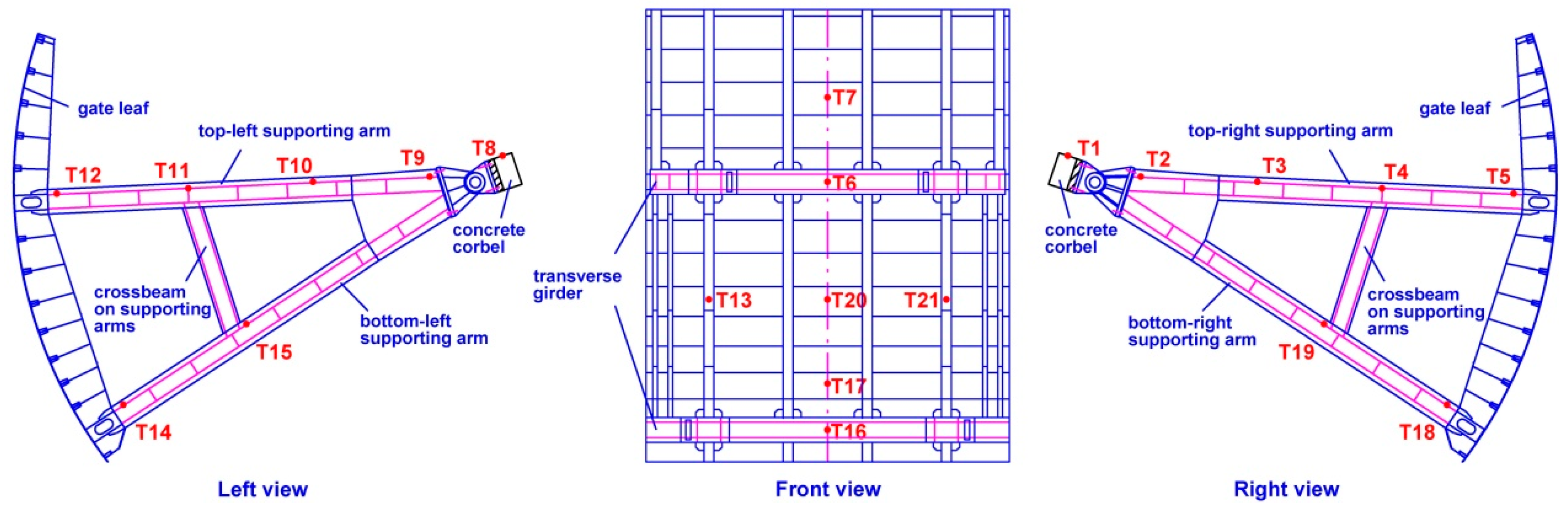
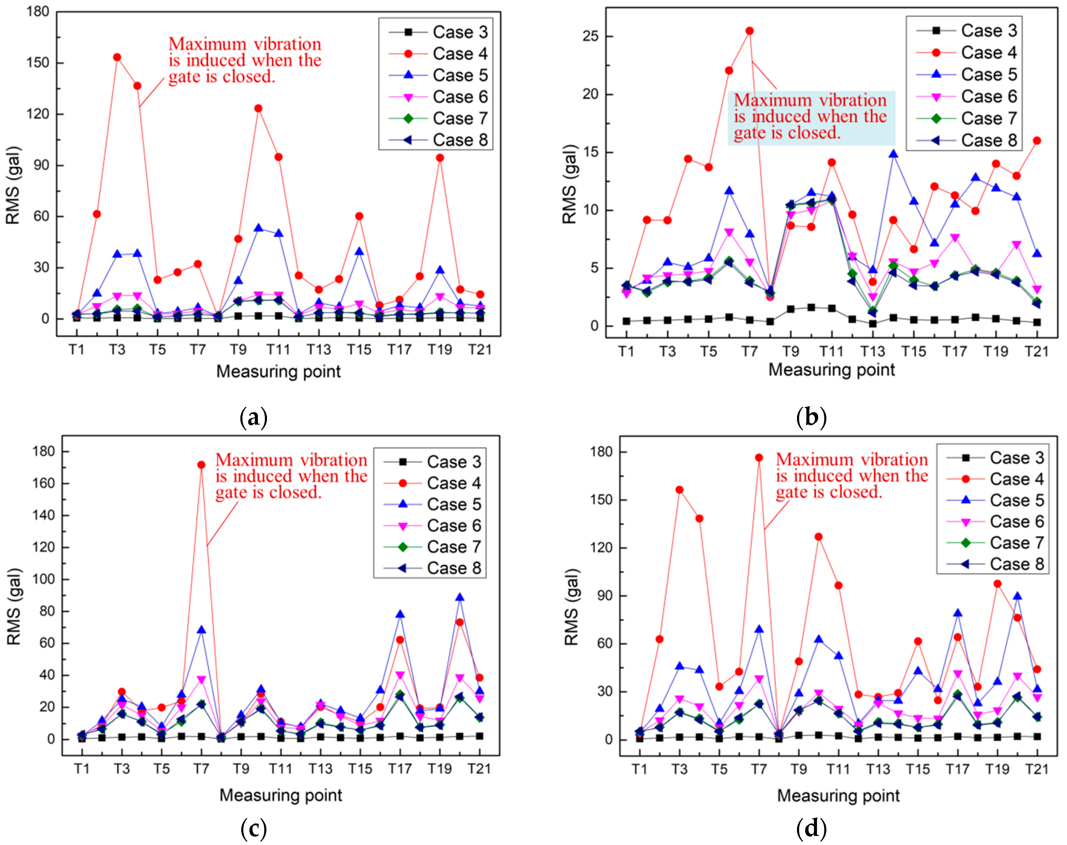
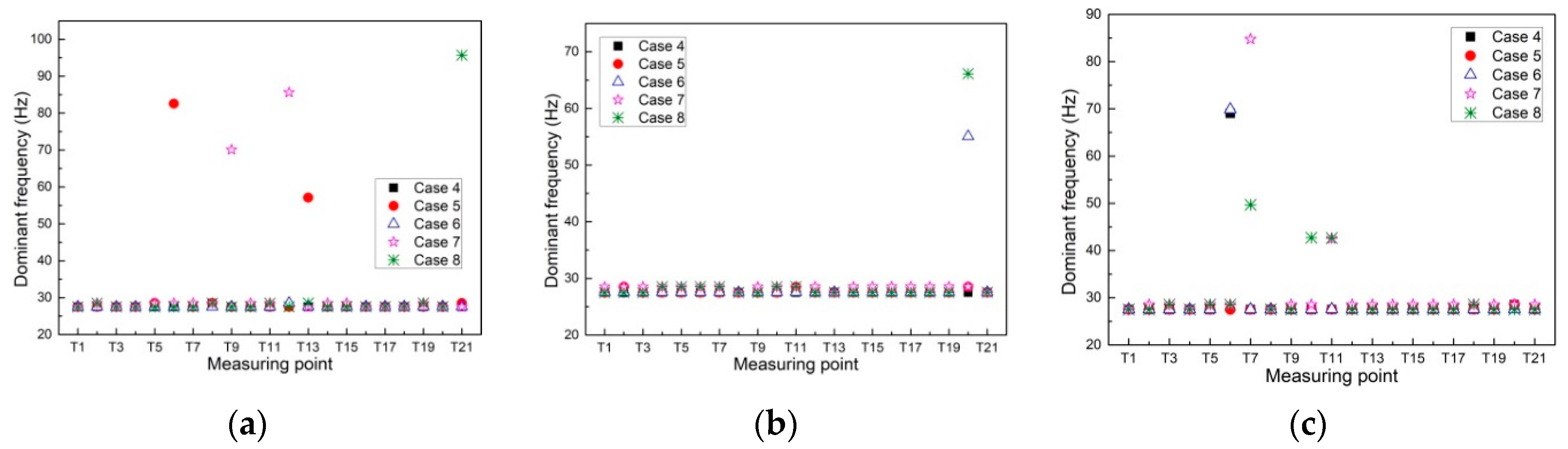
2.3. Vibration of the Surface Outlet Radial Gate
2.4. Preliminary Analysis of the Causes of the Hydraulic Gate Vibration
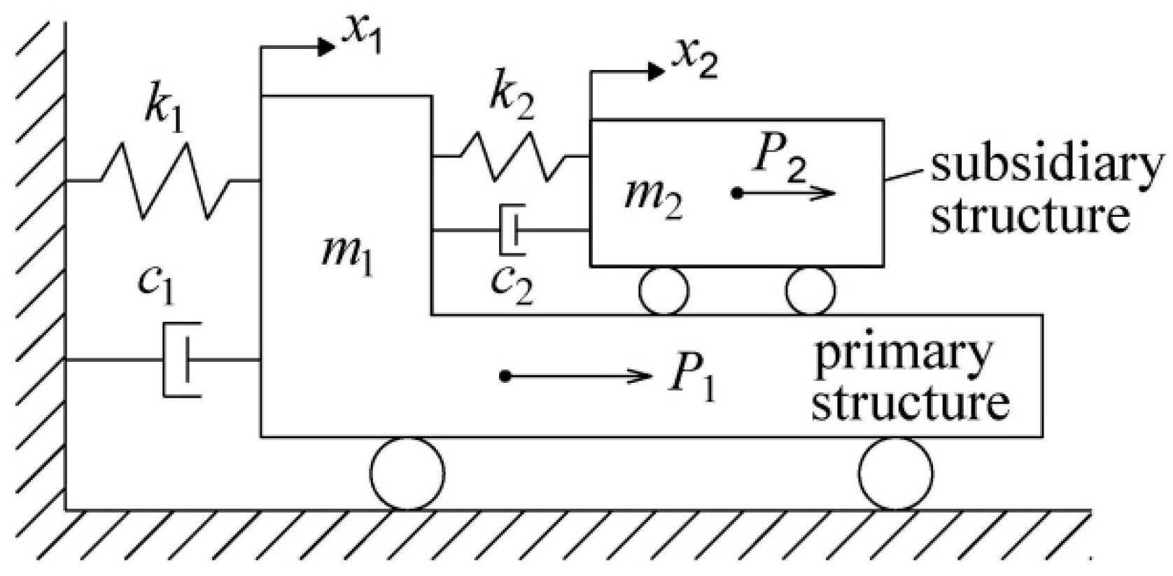
3. Dynamic Response for an Accessory Structure Equipped on the Primary Structure
3.1. Theoretical Model
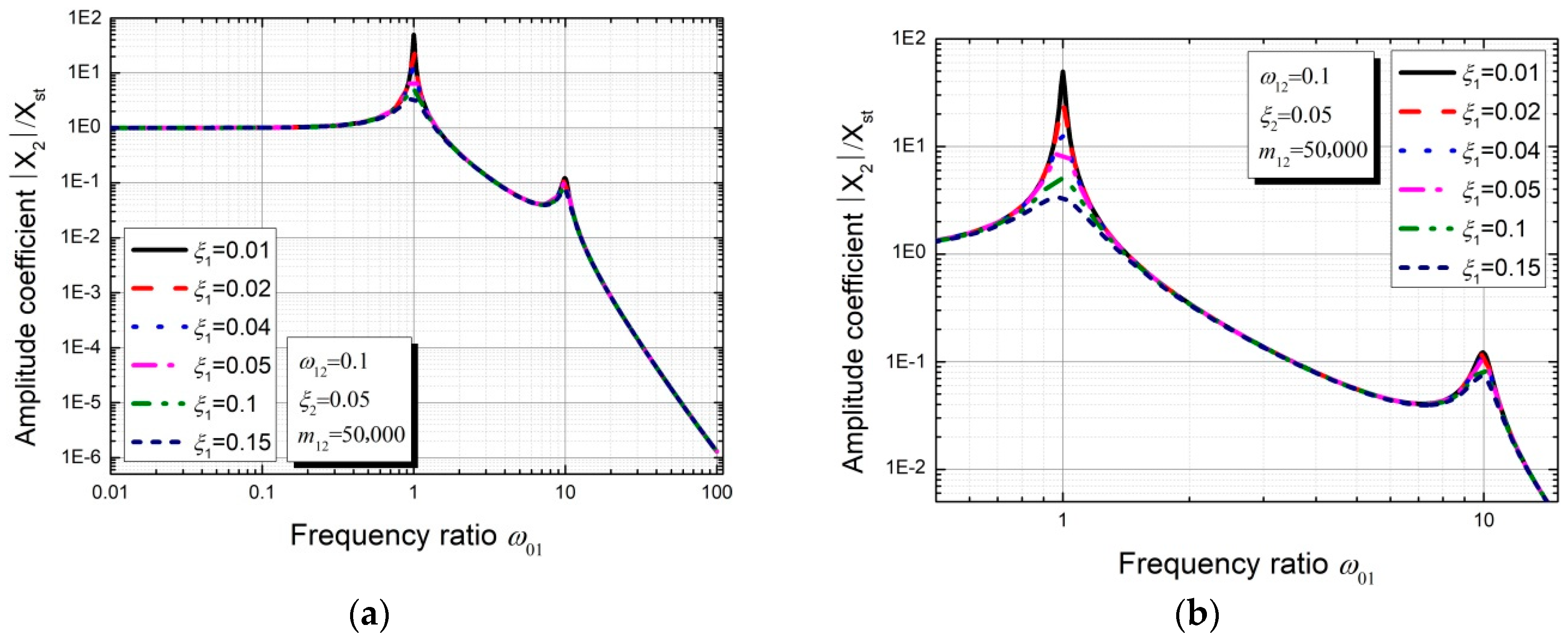
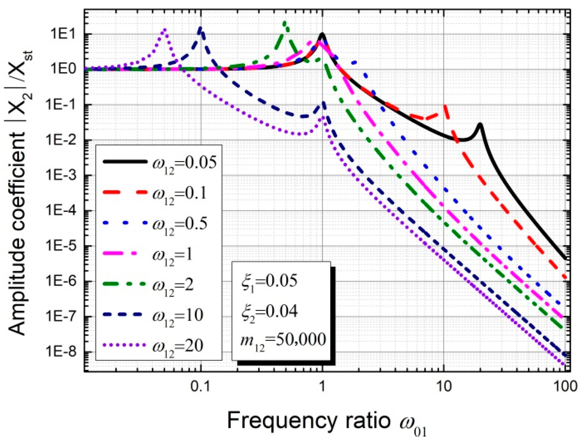
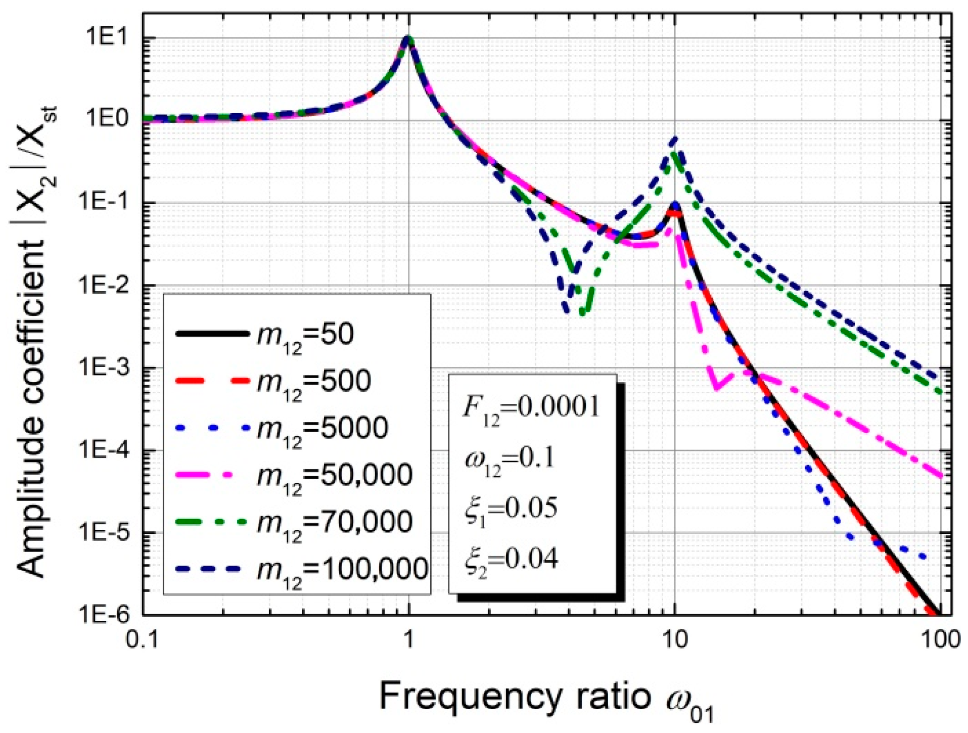
3.2. Parameter Sensitivity Analysis of the Theoretical Model without Considering Excitation P2
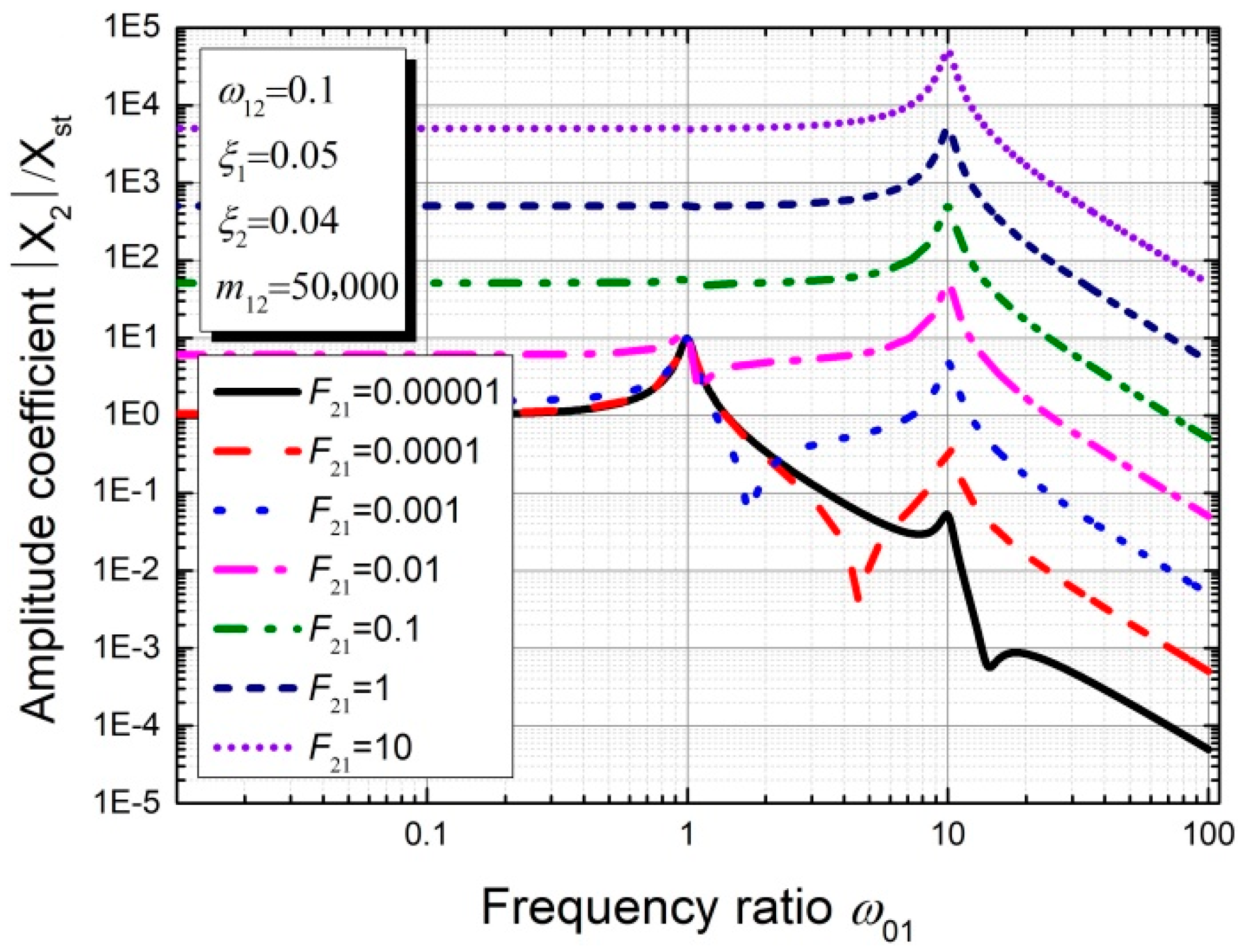
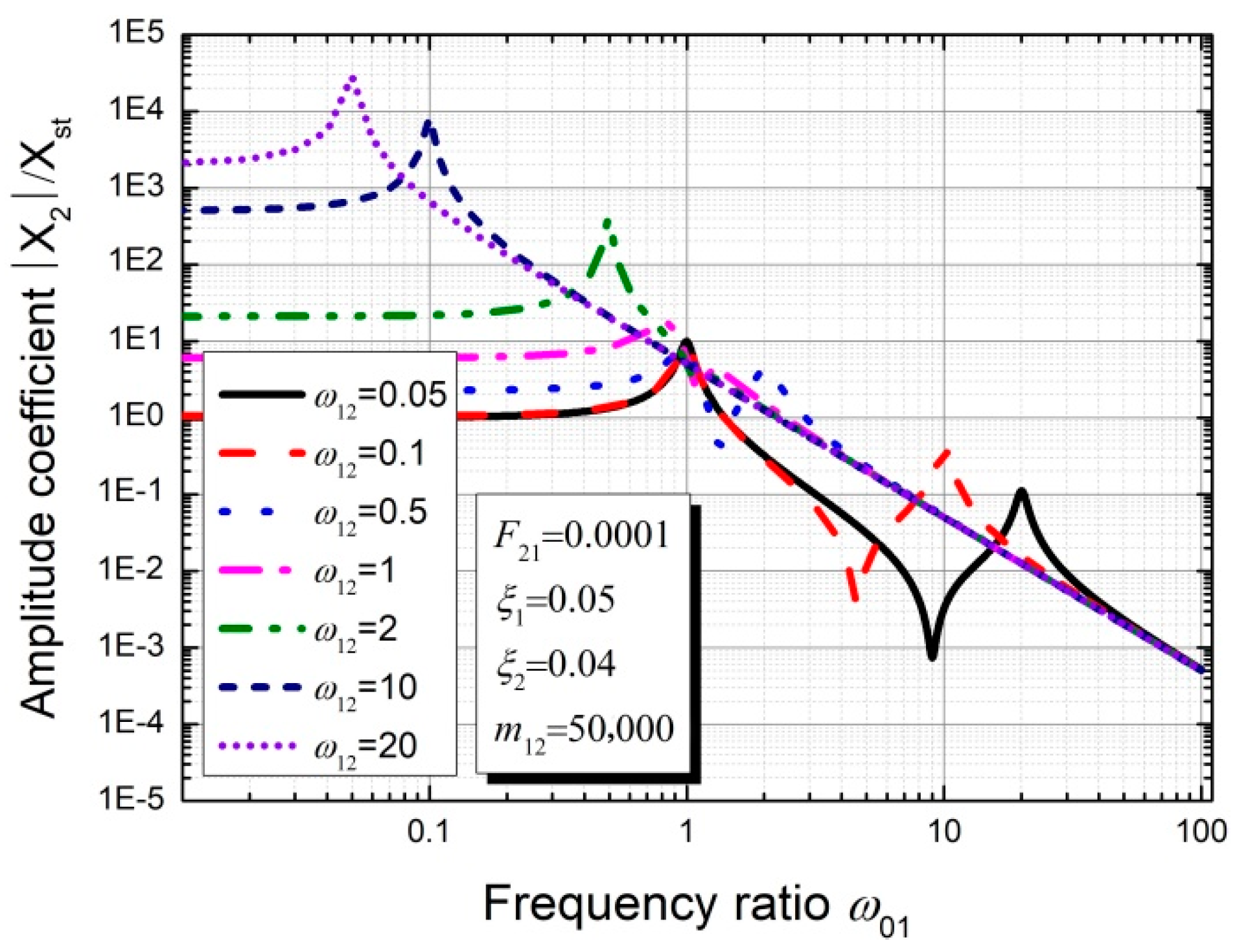
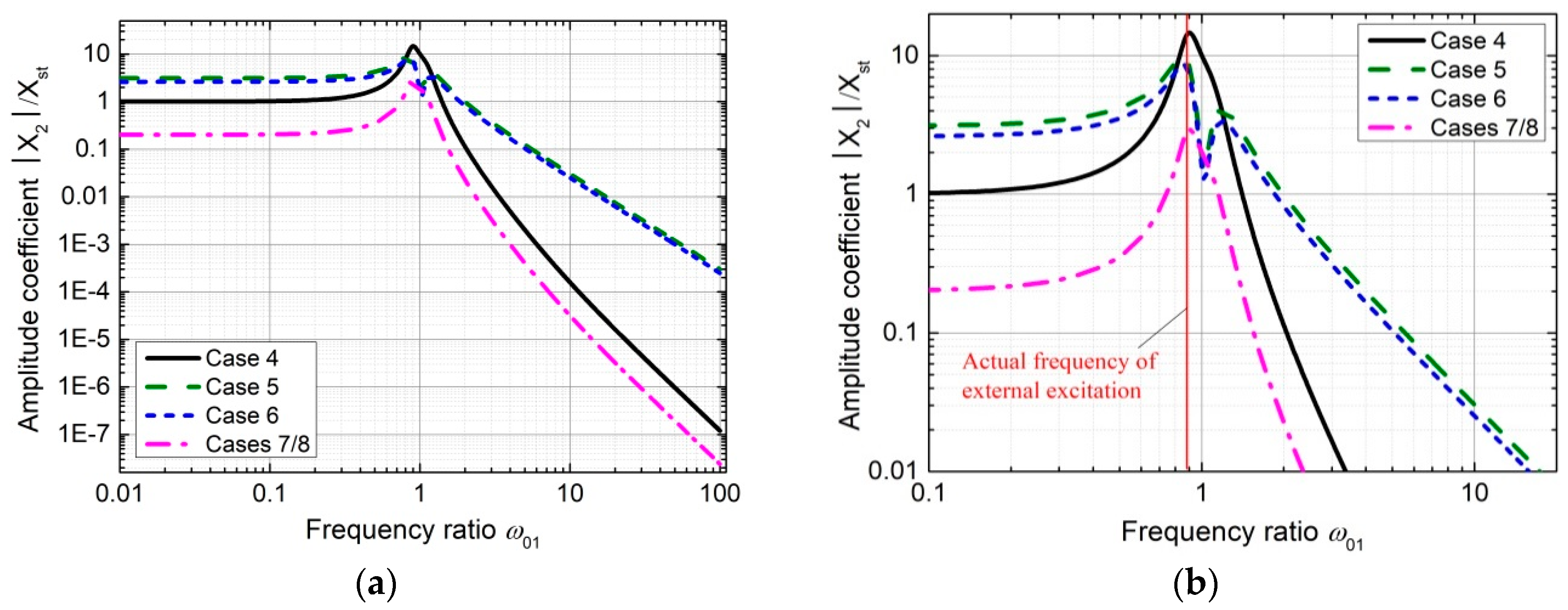
3.3. Parameter Sensitivity Analysis of the Theoretical Model Considering Excitation P2
4. Modal Analysis of the 3# Surface Orifice Gate
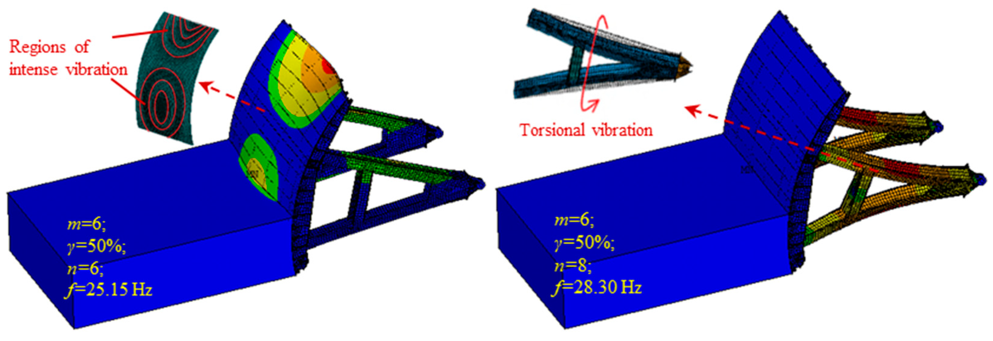
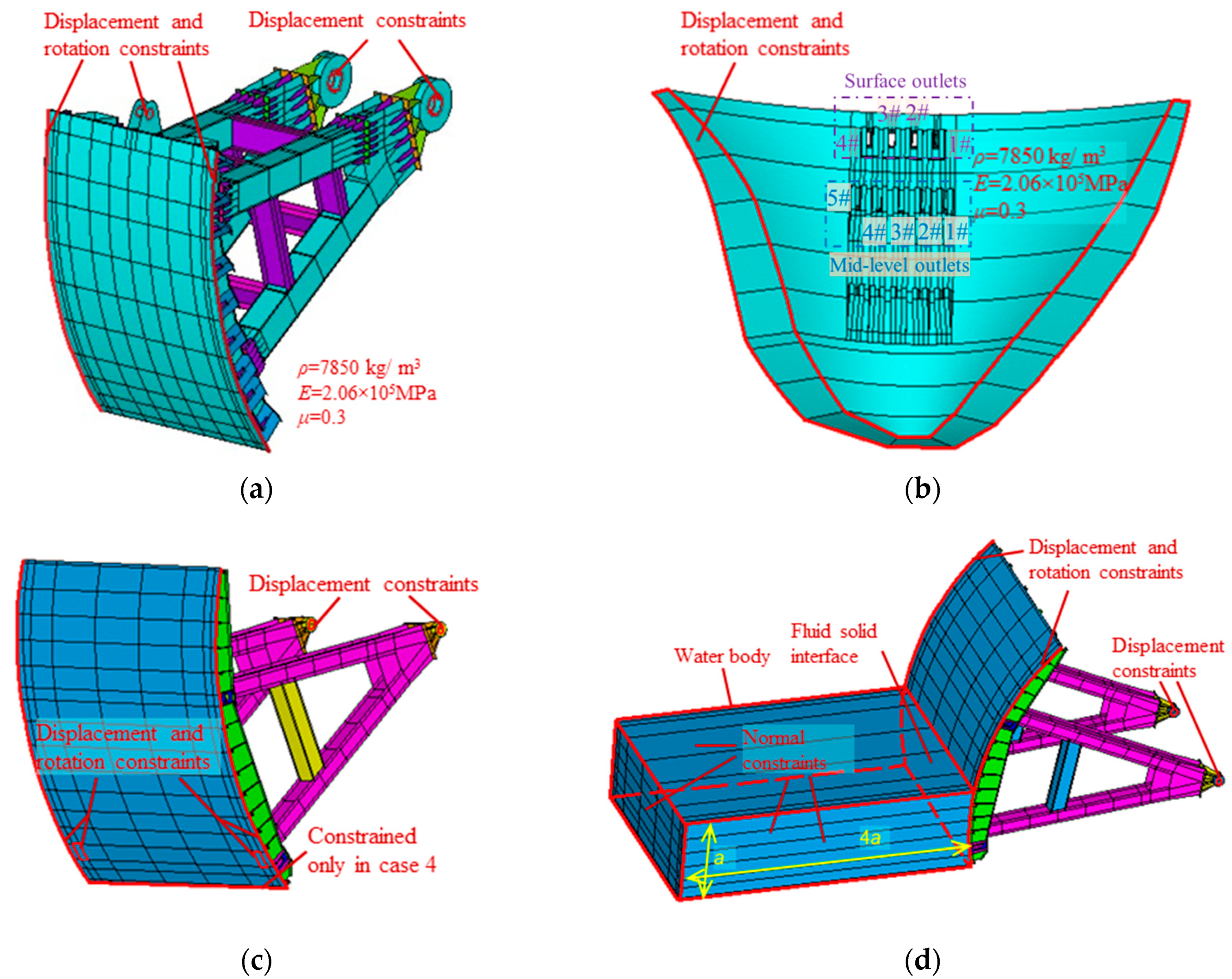
4.1. Modal Analysis Based on Numerical Simulation
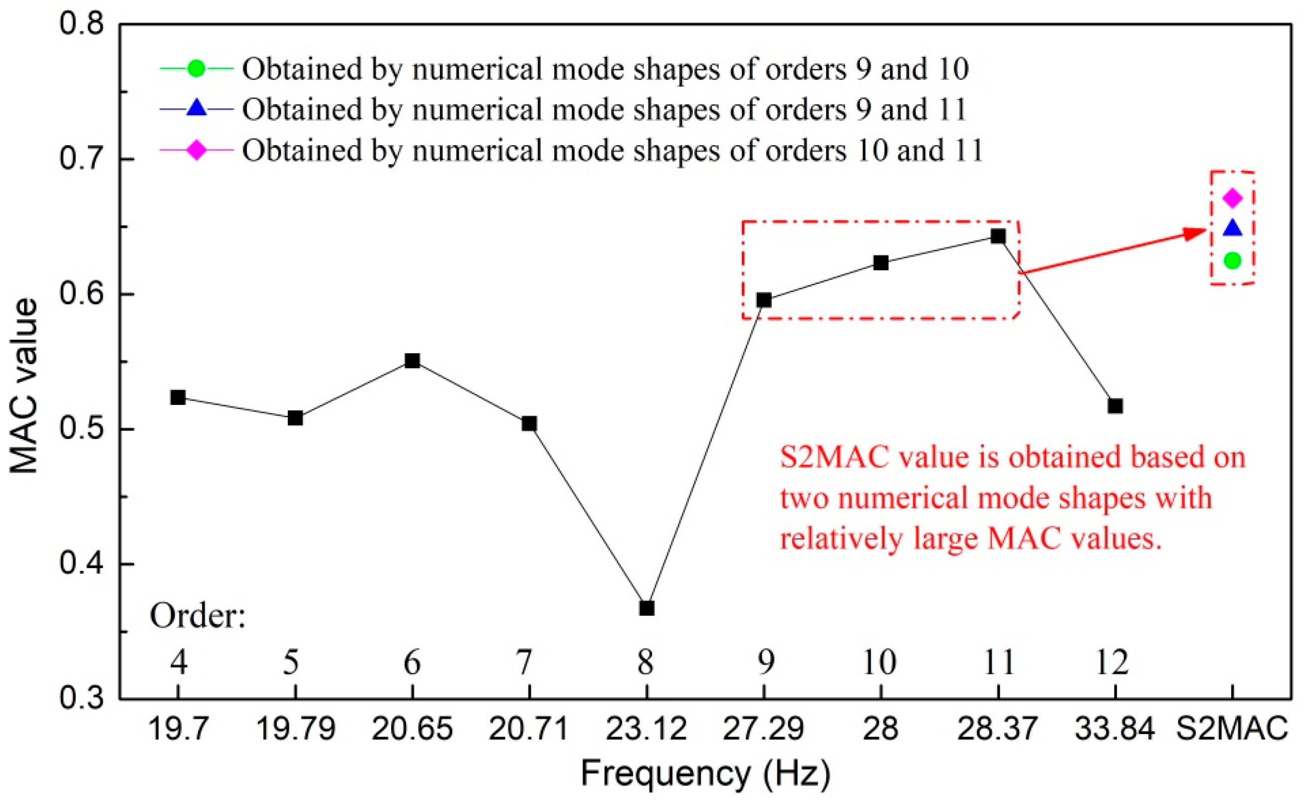
4.2. Correlation Analysis of the Prototype and Numerical Vibration Modes
5. Cause and Mechanism of the Intense Vibration of the 3# Surface Outlet Gate
6. Concluding Remarks
Author Contributions
Funding
Conflicts of Interest
References
- Lian, J.; Zhang, J.; Wang, H. Study on damage diagnosis of guide wall based on flood discharge response. J. Hydroelectr. Eng. 2008, 27, 96–101. [Google Scholar]
- He, L.; Lian, J.; Ma, B. Intelligent damage identification method for large structures based on strain modal parameters. J. Vib. Control 2014, 20, 1783–1795. [Google Scholar] [CrossRef]
- Lian, J.J.; Peng, M.X.; Cui, G.T.; Lin, J.Y. On the stability of gate vibrations. J. Tianjin Univ. (Sci. Technol.) 1999, 32, 171–176. [Google Scholar]
- Yin, J.B.; Liang, Z.X.; Gong, H.L. Experimental study on application & development of X type flaring gate piers. J. Hydroelectr. Eng. 2007, 26, 36–39. [Google Scholar]
- Darbre, G.R.; Smet, C.A.M.D.; Kraemer, C. Natural frequencies measured from ambient vibration response of the arch dam of Mauvoisin. Earthq. Eng. Struct. Dyn. 2015, 29, 577–586. [Google Scholar] [CrossRef]
- Proulx, J.; Paultre, P.; Rheault, J.; Robert, Y. An experimental investigation of water level effects on the dynamic behaviour of a large arch dam. Earthq. Eng. Struct. Dyn. 2001, 30, 1147–1166. [Google Scholar] [CrossRef]
- Lian, J.J.; Liu, X.Z.; Ma, B. Safety evaluation and the static-dynamic coupling analysis of counter-arched slab in plunge pool. Sci. China Ser. E-Technol. Sci. 2009, 52, 1397–1412. [Google Scholar] [CrossRef]
- He, L.; Lian, J.; Ma, B.; Wang, H. Optimal multiaxial sensor placement for modal identification of large structures. Struct. Control Health Monit. 2013, 21, 61–79. [Google Scholar] [CrossRef]
- Zhang, Y.; Lian, J.; Liu, F. An improved filtering method based on EEMD and wavelet-threshold for modal parameter identification of hydraulic structure. Mech. Syst. Signal Process. 2016, 68–69, 316–329. [Google Scholar] [CrossRef]
- Lian, J.J.; Zhang, Y.; Liu, F.; Zhao, Q.H. Analysis of the ground vibration induced by high dam flood discharge using the cross wavelet transform method. J. Renew. Sustain. Energy 2015, 7, 043146. [Google Scholar] [CrossRef]
- Liang, C.; Zhang, J.L.; Lian, J.J.; Liu, F.; Li, X.Y. Probabilistic analysis for the response of nonlinear base isolation system under the ground excitation induced by high dam flood discharge. Earthq. Eng. Eng. Vib. 2017, 16, 841–857. [Google Scholar] [CrossRef]
- Hardwick, J.D. Flow-induced vibration of vertical-lift gate. J. Hydraul. Div. 1974, 100, 631–644. [Google Scholar]
- Kolkman, P.A.; Vrijer, A. Gate edge suction as a cause of self-exciting vertical vibrations. In Proceedings of the 17th Congress of the International Association for Hydraulic Resources, Baden-Baden, Germany, 14–19 August 1977. [Google Scholar]
- Thang, N.D.; Naudascher, E. Vortex-excited vibrations of underflow gates. J. Hydraul. Res. 1986, 24, 133–151. [Google Scholar] [CrossRef]
- Thang, N.D.; Naudascher, E. Self-excited vibrations of vertical-lift gates. J. Hydraul. Res. 1986, 24, 391–404. [Google Scholar] [CrossRef]
- Ishii, N.; Naudascher, E. A design criterion for dynamic stability of Tainter gates. J. Fluid Struct. 1992, 6, 67–84. [Google Scholar] [CrossRef]
- Yan, G.H.; Chen, F.Z.; Zhao, J.P. Prototype observation study on the flow-induced vibration of surface radial gate. J. Hydroelectr. Eng. 2006, 25, 45–50. [Google Scholar]
- Ormondroyd, J.; Den, H.J.P. The theory of the dynamic vibration absorber. ASME J. Appl. Mech. 1928, 50, 9–22. [Google Scholar]
- Warburton, G.B. Optimum absorber parameters for minimizing vibration response. Earthq. Eng. Struct. Dyn. 1981, 9, 251–262. [Google Scholar] [CrossRef]
- Zuo, L.; Nayfeh, S.A. Optimization of the individual stiffness and damping parameters in multiple-tuned-mass damper systems. J. Vib. Acoust. Trans. ASME 2003, 127, 77–83. [Google Scholar] [CrossRef]
- Zuo, L.; Nayfeh, S.A. Minimax optimization of multi-degree-of-freedom tuned-mass dampers. J. Sound Vib. 2004, 272, 893–908. [Google Scholar] [CrossRef]
- Dinh, V.N.; Basu, B. Passive control of floating offshore wind turbine nacelle and spar vibrations by multiple tuned mass dampers. Struct. Control Health Monit. 2015, 22, 152–176. [Google Scholar] [CrossRef]
- Zhu, J.T.; Xu, Z.-D.; Guo, Y.-Q. Magnetoviscoelasticity parametric model of an MR elastomer vibration mitigation device. Smart Mater. Struct. 2012, 21, 075034. [Google Scholar] [CrossRef]
- Weber, F.; Distl, H. Amplitude and frequency independent cable damping of Sutong Bridge and Russky Bridge by magnetorheological dampers. Struct. Control Health Monit. 2015, 22, 237–254. [Google Scholar] [CrossRef]
- Lee, H.P. Dynamic response of girder bridge with a moving mass. J. Sound Vib. 1996, 191, 289–294. [Google Scholar] [CrossRef]
- Peng, X.; Yin, X.F.; Fang, Z. Vibration and TMD control of coupled system of girder bridge and vehicle with variable speeds. J. Hunan Univ. (Nat. Sci.) 2006, 33, 61–66. [Google Scholar]
- Miguel, L.F.F.; Lopez, R.H.; Torii, A.J.; Miguel, L.F.F.; Beck, A.T. Robust design optimization of TMDs in vehicle–bridge coupled vibration problems. Eng. Struct. 2016, 126, 703–711. [Google Scholar] [CrossRef]
- Lackner, M.A.; Rotea, M.A. Structural control of floating wind turbines. Mechatronics 2011, 21, 704–719. [Google Scholar] [CrossRef]
- Stewart, G.; Lackner, M. Offshore Wind Turbine Load Reduction Employing Optimal Passive Tuned Mass Damping Systems. IEEE Trans. Control Syst. Technol. 2013, 21, 1090–1104. [Google Scholar] [CrossRef]
- Si, Y.; Karimi, H.R.; Gao, H. Modelling and optimization of a passive structural control design for a spar-type floating wind turbine. Eng. Struct. 2014, 69, 168–182. [Google Scholar] [CrossRef]
- Mackriell, L.E.; Kwok, K.C.S.; Samali, B. Critical mode control of a wind-loaded tall building using an active tuned mass damper. Eng. Struct. 1997, 19, 834–842. [Google Scholar] [CrossRef]
- Pinkaew, T.; Lukkunaprasit, P.; Chatupote, P. Seismic effectiveness of tuned mass dampers for damage reduction of structures. Eng. Struct. 2003, 25, 39–46. [Google Scholar] [CrossRef]
- Anh, N.D.; Nguyen, N.X. Extension of equivalent linearization method to design of TMD for linear damped systems. Struct. Control Health Monit. 2012, 19, 565–573. [Google Scholar] [CrossRef]
- Wang, Z.; Chen, G. Analytical mode decomposition with Hilbert transform for modal parameter identification of buildings under ambient vibration. Eng. Struct. 2014, 59, 173–184. [Google Scholar] [CrossRef]
- Liu, B.J. Study on the Similarity Law and Characteristics of Fluctuating Pressures in Supercritical Flow; Tianjin University: Tianjin, China, 2013. [Google Scholar]
- Ishii, N.; Knisely, C.W.; Nakata, A. Coupled-Mode Vibration of Gates with Simultaneous Over- and Underflow. J. Fluid Struct. 1994, 8, 455–469. [Google Scholar] [CrossRef]
- Clough, R.W.; Penzien, J.; Griffin, D.S. Dynamics of Structures, 2nd ed.; McGraw-Hill, Inc.: New York, NY, USA, 1993. [Google Scholar]
- Group, A.C. ANSYS15.0 User’s Manual; ANSYS, Inc.: Pittsburgh, PA, USA, 2013. [Google Scholar]
- Kolkman, P.A. A simple scheme for calculating the added mass of hydraulic gates. J. Fluids Struct. 1988, 2, 339–353. [Google Scholar] [CrossRef]
- Lian, J.J.; Yang, M. Hydrodynamics for High Dam; China Water & Power Press: Beijing, China, 2008. [Google Scholar]
- Feng, Z.; Shen, W.; Chen, Z. Consistent Multilevel RDT-ERA for Output-Only Ambient Modal Identification of Structures. Int. J. Struct. Stab. Dyn. 2017, 17, 1750106. [Google Scholar] [CrossRef]
- Cole, H., Jr. On-the-line analysis of random vibrations. In 9th Structural Dynamics and Materials Conference; American Institute of Aeronautics and Astronautics: Reston, VA, USA, 1968. [Google Scholar] [CrossRef]
- Bedewi, N.E. The Mathematical Foundation of the Auto and Cross-Random Decrement Techniques and the Development of a System Identification Technique for the Detection Structural Deterioration; University of Maryland: College Park, MD, USA, 1986. [Google Scholar]
- Allemang, R.J.; Brown, D.L. A correlation coefficient for modal vector analysis. In Proceedings of the 1st International Modal Analysis Conference, Orlando, FL, USA, 8–10 November 1982; pp. 110–116. [Google Scholar]
- D’Ambrogio, W.; Fregolent, A. Higher-Order Mac for the Correlation of Close and Multiple Modes. Mech. Syst. Signal Process. 2003, 17, 599–610. [Google Scholar] [CrossRef]
- López-Aenlle, M.; Brincker, R.; Pelayo, F.; Canteli, A.F. On exact and approximated formulations for scaling-mode shapes in operational modal analysis by mass and stiffness change. J. Sound Vib. 2012, 331, 622–637. [Google Scholar] [CrossRef]
- Brincker, R.; Skafte, A.; López-Aenlle, M.; Sestieri, A.; D’Ambrogio, W.; Canteli, A. A local correspondence principle for mode shapes in structural dynamics. Mech. Syst. Signal Process. 2014, 45, 91–104. [Google Scholar] [CrossRef]
- Ministry of Housing and Urban-Rural Development of the People’s Republic of China; Inspection and Quarantine of the People’s Republic of China General Administration of Quality Supervision. Code for Seismic Design of Buildings; China Architecture & Building Press: Beijing, China, 2010.


| Case | Upstream Water Level (m) | Discharge from Dam Body (m3/s) | Downstream Water Level (m) | Opening Ratios of Different Outlets | Gate Installed with Sensors | ||||||
|---|---|---|---|---|---|---|---|---|---|---|---|
| Surface Outlet No. | Mid-Level Outlet No. | ||||||||||
| 1# | 2# | 3# | 4# | 2# | 3# | 4# | |||||
| 1 | 1879.73 | ≈1090 | 1651.02 | 0 | 0 | 0 | 0 | 0 | 100% | 0 | 3# mid-level outlet gate |
| 2 | 1880 | 2080 | 1647.53 | 0 | 0 | 0 | 0 | 100% | 0 | 100% | 2# and 4# mid-level outlet gate |
| 3 | 1880 | 3840 | 1650.02 | 100% | 100% | 100% | 100% | 0 | 0 | 0 | 3# surface outlet gate |
| 4 | ≈1879.14 | ≈2668 | ≈1649.37 | 30% | 0 | 0 | 30% | 100% | 0 | 100% | 3# surface outlet gate |
| 5 | ≈1879.14 | ≈2913 | ≈1649.37 | 30% | 0 | 25% | 30% | 100% | 0 | 100% | 3# surface outlet gate |
| 6 | ≈1879.14 | ≈3158 | ≈1649.37 | 30% | 0 | 50% | 30% | 100% | 0 | 100% | 3# surface outlet gate |
| 7 | ≈1879.14 | ≈3403 | ≈1649.37 | 30% | 0 | 75% | 30% | 100% | 0 | 100% | 3# surface outlet gate |
| 8 | ≈1879.14 | ≈3648 | ≈1649.37 | 30% | 0 | 100% | 30% | 100% | 0 | 100% | 3# surface outlet gate |
| Order | Natural Frequency | Order | Natural Frequency | ||||
|---|---|---|---|---|---|---|---|
| Dry Mode | Wet Mode | Difference | Dry Mode | Wet Mode | Difference | ||
| 1 | 1.78 | 1.55 | 12.98% | 208 | 26.08 | 25.61 | 1.80% |
| 2 | 2.59 | 2.27 | 12.54% | 222 | 26.93 | 26.28 | 2.41% |
| 5 | 3.07 | 2.97 | 3.37% | 223 | 27.05 | 26.47 | 2.14% |
| 6 | 3.39 | 3.12 | 7.89% | 237 | 27.94 | 27.32 | 2.22% |
| 9 | 3.77 | 3.54 | 6.10% | 238 | 28.04 | 27.49 | 1.96% |
| 10 | 3.8 | 3.70 | 2.60% | 254 | 28.99 | 28.64 | 1.21% |
| Order | Natural Frequency | Order | Natural Frequency | ||||||
|---|---|---|---|---|---|---|---|---|---|
| Case 4 (wet) | Case 5 (wet) | Case 6 (wet) | Case 7/8 (dry) | Case 4 (wet) | Case 5 (wet) | Case 6 (wet) | Case 7/8 (dry) | ||
| 4 | 19.70 | 19.69 | 20.31 | 20.36 | 9 | 27.29 | 28.39 | 28.83 | 43.17 |
| 5 | 19.79 | 20.62 | 20.69 | 25.77 | 10 | 28.00 | 30.18 | 36.53 | 45.17 |
| 6 | 20.65 | 20.67 | 25.15 | 27.81 | 11 | 28.37 | 32.42 | 45.32 | 45.43 |
| 7 | 20.71 | 26.11 | 28.08 | 27.92 | 12 | 33.84 | 35.02 | 45.40 | 56.04 |
| 8 | 23.12 | 28.30 | 28.30 | 40.98 | |||||
| Mode No. | Modal Frequencies in Different Cases | Mode No. | Modal Frequencies in Different Cases | ||||||||
|---|---|---|---|---|---|---|---|---|---|---|---|
| Case 4 | Case 5 | Case 6 | Case 7 | Case 8 | Case 4 | Case 5 | Case 6 | Case 7 | Case 8 | ||
| 1 | 0.65 | 0.67 | 0.86 | 0.59 | 0.60 | 5 | 127.40 | 119.73 | 159.84 | 157.90 | 157.49 |
| 2 | 27.51 | 27.50 | 27.53 | 28.18 | 28.07 | 6 | 128.74 | 173.88 | 170.40 | 182.55 | 180.19 |
| 3 | 44.22 | 63.21 | 52.48 | 91.61 | 92.86 | 7 | 193.29 | 201.29 | 200.07 | 200.03 | 199.73 |
| 4 | 67.49 | 95.06 | 111.54 | 110.09 | 110.25 | ||||||
| Measuring Point | Mode Shape Obtained by Prototype Data and Numerical Simulation | |||||||||
|---|---|---|---|---|---|---|---|---|---|---|
| Prototype Frequency (Hz)/Order | Numerical Frequency (Hz)/Order | |||||||||
| 27.51/2 | 19.70/4 | 19.79/5 | 20.65/6 | 20.71/7 | 23.12/8 | 27.29/9 | 28.00/10 | 28.37/11 | 33.84/12 | |
| T1 | 0.1364 | 0.0001 | 0.0001 | 0.0001 | 0.0001 | 0.0001 | 0.0001 | 0.0001 | 0.0001 | 0.0001 |
| T2 | 0.1551 | 0.3203 | 0.2987 | 0.3679 | 0.3315 | 0.2580 | 0.4299 | 0.4669 | 0.4773 | 0.4835 |
| T3 | 0.9211 | 0.7856 | 0.7417 | 0.8953 | 0.8095 | 0.6384 | 0.8558 | 0.9370 | 0.9609 | 1.0000 |
| T4 | 1.0000 | 0.8729 | 0.7881 | 0.7453 | 0.8393 | 0.5080 | 1.0000 | 1.0000 | 1.0000 | 0.3846 |
| T5 | 0.0358 | 0.1500 | 0.1172 | 0.1047 | 0.0899 | 0.0786 | 0.4486 | 0.1417 | 0.1266 | 0.4103 |
| T18 | 0.0758 | 0.0975 | 0.1305 | 0.0864 | 0.0798 | 0.0528 | 0.1159 | 0.0945 | 0.0828 | 0.1139 |
| T19 | 0.0912 | 0.8898 | 1.0000 | 1.0000 | 0.9226 | 1.0000 | 0.9092 | 0.9055 | 0.8984 | 0.2275 |
| T8 | 0.0875 | 0.0001 | 0.0001 | 0.0001 | 0.0001 | 0.0001 | 0.0702 | 0.0001 | 0.0055 | 0.0001 |
| T9 | 0.0738 | 0.3525 | 0.2543 | 0.3387 | 0.3613 | 0.2598 | 0.4272 | 0.4669 | 0.4789 | 0.4799 |
| T10 | 0.1511 | 0.8322 | 0.6099 | 0.7925 | 0.8452 | 0.6205 | 0.8224 | 0.6724 | 0.5414 | 0.9670 |
| T11 | 0.4046 | 0.9492 | 0.6689 | 0.8557 | 0.9107 | 0.5107 | 0.9907 | 1.0000 | 1.0000 | 0.3773 |
| T12 | 0.3983 | 0.1636 | 0.0980 | 0.0962 | 0.0976 | 0.0786 | 0.4459 | 0.3772 | 0.4383 | 0.4103 |
| T14 | 0.0366 | 0.1119 | 0.1152 | 0.0782 | 0.0857 | 0.0521 | 0.1139 | 0.0937 | 0.0820 | 0.1136 |
| T15 | 0.1249 | 1.0000 | 0.8742 | 0.9179 | 1.0000 | 1.0000 | 0.9012 | 0.9055 | 0.9063 | 0.2315 |
| T6 | 0.0721 | 0.0811 | 0.0007 | 0.0006 | 0.0113 | 0.0085 | 0.1258 | 0.0007 | 0.0106 | 0.3410 |
| T7 | 0.0328 | 0.0506 | 0.0026 | 0.0002 | 0.0034 | 0.0000 | 0.0861 | 0.0000 | 0.0017 | 0.0228 |
| T13 | 0.0646 | 0.0015 | 0.0072 | 0.0005 | 0.0000 | 0.0130 | 0.0228 | 0.0012 | 0.0009 | 0.2366 |
| T16 | 0.0046 | 0.0106 | 0.0077 | 0.0012 | 0.0046 | 0.0027 | 0.0226 | 0.0002 | 0.0054 | 0.0447 |
| T17 | 0.0574 | 0.0061 | 0.0015 | 0.0003 | 0.0022 | 0.0036 | 0.0323 | 0.0015 | 0.0019 | 0.0324 |
| T20 | 0.1135 | 0.0049 | 0.0012 | 0.0001 | 0.0011 | 0.0049 | 0.0311 | 0.0005 | 0.0013 | 0.0319 |
| T21 | 0.0694 | 0.0020 | 0.0057 | 0.0006 | 0.0000 | 0.0163 | 0.0260 | 0.0010 | 0.0010 | 0.2872 |
© 2020 by the authors. Licensee MDPI, Basel, Switzerland. This article is an open access article distributed under the terms and conditions of the Creative Commons Attribution (CC BY) license (http://creativecommons.org/licenses/by/4.0/).
Share and Cite
Lian, J.; Chen, L.; Ma, B.; Liang, C. Analysis of the Cause and Mechanism of Hydraulic Gate Vibration during Flood Discharging from the Perspective of Structural Dynamics. Appl. Sci. 2020, 10, 629. https://doi.org/10.3390/app10020629
Lian J, Chen L, Ma B, Liang C. Analysis of the Cause and Mechanism of Hydraulic Gate Vibration during Flood Discharging from the Perspective of Structural Dynamics. Applied Sciences. 2020; 10(2):629. https://doi.org/10.3390/app10020629
Chicago/Turabian StyleLian, Jijian, Lin Chen, Bin Ma, and Chao Liang. 2020. "Analysis of the Cause and Mechanism of Hydraulic Gate Vibration during Flood Discharging from the Perspective of Structural Dynamics" Applied Sciences 10, no. 2: 629. https://doi.org/10.3390/app10020629
APA StyleLian, J., Chen, L., Ma, B., & Liang, C. (2020). Analysis of the Cause and Mechanism of Hydraulic Gate Vibration during Flood Discharging from the Perspective of Structural Dynamics. Applied Sciences, 10(2), 629. https://doi.org/10.3390/app10020629