1. Introduction
A radar is an electromagnetic device used for the detection and identification of various targets such as aircraft, ships, and ground vehicles. It transmits electromagnetic waves to targets and receives the reflected signals from the target and clutter. The frequency band and waveform of the transmitted signal are determined by the platform and the type of target to be detected [
1]. In recent years, as the demand for remote sensing systems has increased, technologies tend to have been expanded to multifunctional, wide-band, and multiband surveillance systems [
2,
3,
4]. The expansion of these applications is demanded the very stable radio frequency (RF) sources for obtaining the higher spatial and velocity resolution performance and requires the ability to detect and process broadband ultra-high frequency signals. However, a method based on the DDS (direct digital synthesizer), which is currently widely used, has a limited frequency range of the generated signal to a maximum of several GHz; therefore, in order to up-convert to the desired frequency band, several steps of frequency multiplication are required, and the phase noise of the signal is degraded in this process. To solve this problem, as a new field of optoelectronics, photonic-based microwave technology has been proposed [
5,
6,
7]. Microwave photonics offers a wide bandwidth, resistance to electromagnetic interference, lower propagation distortion, lower phase noise, and higher frequency flexibility compare to those of the conventional electronics-based technology.
Depending on the type of laser source employed, the radars adopting the microwave photonics technology can be divided into a pulsed radar applying a mode-locked laser (MLL) and a frequency modulated continuous-wave (FMCW) radar using continuous-wave (CW) laser [
8,
9,
10,
11,
12]. A pulsed radar using an MLL can detect the lower radar cross-section (RCS) targets with the same power consumption compared to an FMCW radar. However, due to the characteristics of the MLL that outputs a signal having a specific frequency using a resonance, it is difficult to generate the wideband signals, so there is a disadvantage that the range resolution cannot be fine. Therefore, when two or more targets are in close proximity to each other, there is a limitation to separate the targets and the quality of the inverse synthetic aperture radar (ISAR) image is deteriorating due to a low resolution when the ISAR image is acquired. In contrast, an FMCW radar has the advantage of being able to easily generate broadband signals without the minimum detectable range limitation as known as a blind region. However, for the detection of low RCS targets with the same range, the power handling capability of the power amplifier used in the transmitter has to be very high compared with a pulsed radar’s because of the continuously high energy transmitting [
13]. In addition, the large amount of heat, which is generated in the power amplifier, causes the increase in thermal noise and the degradation of the noise figure of the system. Therefore, in order to prevent the generation of thermal noise, an additional cooling system is required, which results in increasing the volume of the system [
14,
15,
16,
17]. For these reasons, the previous studied of the photonic-based pulsed radars with an MLL is mainly focused on for long-range target detection, and the acquisition of high-resolution ISAR images has been studied in photonic-based FMCW radars with a CW laser source [
8,
9,
18,
19,
20,
21,
22,
23,
24]. According to the results of the previous studies, the photonic-based pulsed radar with MLL can replace the conventional electronic-based shipborne radar or airborne radar, and the photonic-based FMCW radar with CW laser can be applied to automobiles, distance measurement, or missile fuses.
In this paper, we propose a photonic-based pulsed radar architecture for the lower RCS target detection with the same average transmission power while maintaining the broadband characteristics of a conventional photonic-based FMCW radar. The proposed photonic-based pulsed radar could overcome the narrow-band disadvantages of an MLL-based pulsed radar by adding a Mach-Zehnder modulator (MZM) operating as an optical switch to the topology with a CW laser source. Therefore, the proposed architecture can be applied to wideband surveillance radars as it can clearly identify the shape of the target due to its excellent range resolution. The organization of this paper is as follows—
Section 2 represents the operation principles of the proposed photonic-based pulsed radar architecture and its theoretical analysis. In
Section 3, the implementation of the prototype applied the proposed photonic-based pulsed radar architecture and the results of indoor experiments are described. Finally,
Section 4 shows the concluding remarks.
2. Principle of the Proposed Architecture
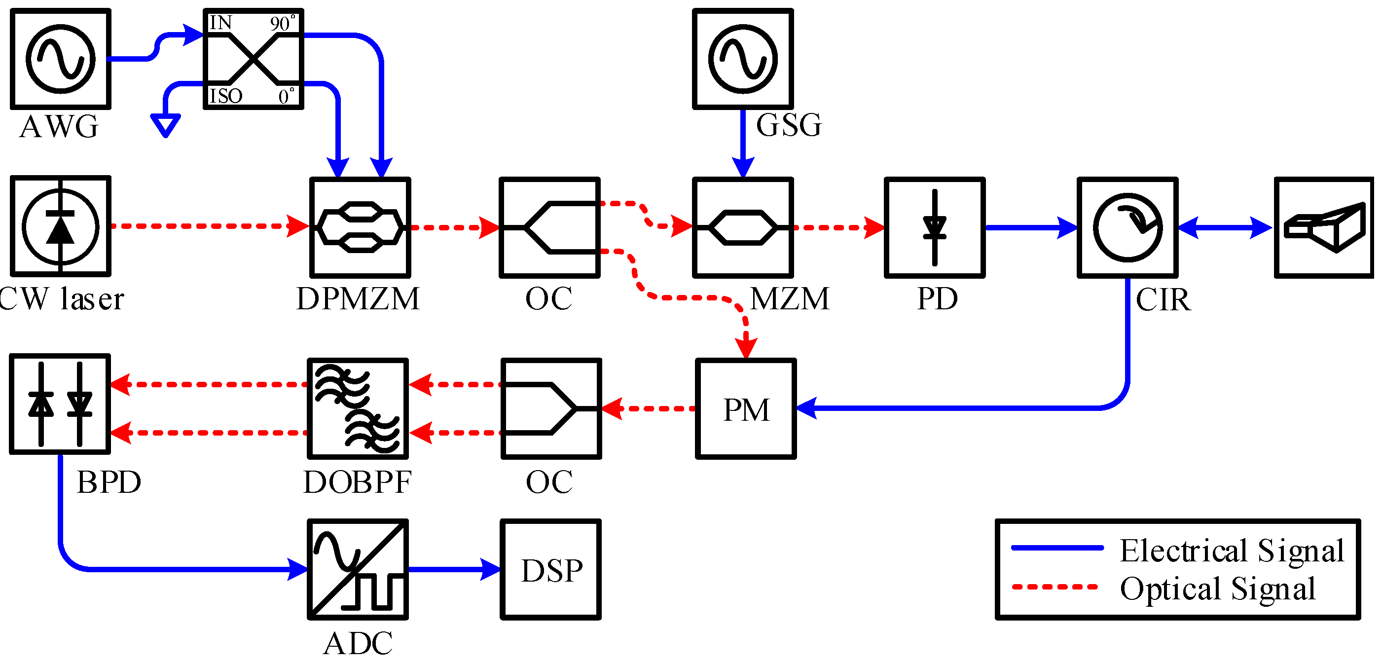
Figure 1 shows the proposed photonic-based pulsed radar architecture. In figures of this paper, the solid-arrow line and the dot-arrow line mean the electrical signal path and the optical signal path, respectively. As shown in
Figure 1, the intermediate frequency (IF) signal from the arbitrary waveform generator (AWG) enters to the RF ports of a dual-parallel Mach-Zehnder modulator (DPMZM) through a 90
hybrid coupler. As studied in Reference [
25], the frequency and bandwidth of the input IF signal with a 90
phase difference is quadrupled by a DPMZM under the proper bias conditions. The quadrupled output signal of a DPMZM is sent to a Mach-Zehnder modulator (MZM) to produce a pulse waveform, which can be able to operate the conventional FMCW radar as a pulsed radar.
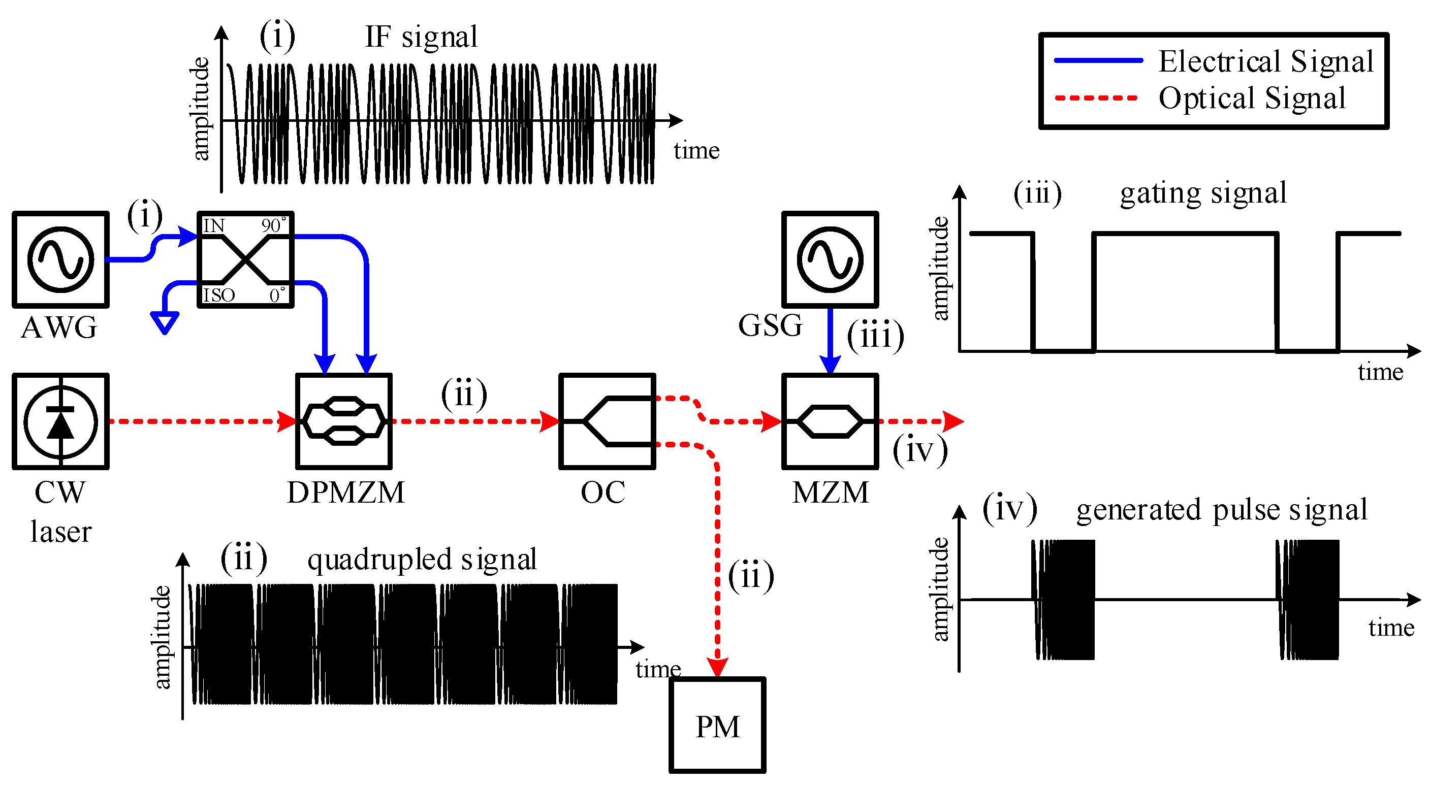
Figure 2 shows the signal waveforms for each node in the proposed architecture in the time domain. It is noted that (ii) and (iv) in
Figure 2 is actually the optical domain signals but they are represented as the electrical domain signals to express clearly the procedure of the pulse signal generation. In
Figure 2, the linear frequency modulation (LFM) signal, (i), from an AWG is quadrupled, (ii), by a DPMZM. By controlling the applied voltage of an MZM as represented at (iii), pulse waveform generation, (iv), can be performed using the quadrupled LFM signal applied to the MZM. As shown in (iv) of
Figure 2, it is confirmed that the output signal of an MZM has both high frequency and broadband characteristics of the signal quadrupled by a DPMZM. In addition, since the pulse repetition frequency (PRF) of the pulse generated by the MZM is determined by the period of the applied signal by a gating signal generator (GSG) of the MZM, therefore, the PRF of the pulsed radar waveform can be changed arbitrarily for applying in the various circumstances. The gated LFM signal by the MZM is converted to the electrical signal through a photodetector (PD) and transmitted to space to detect a target by an antenna.
The operation of the receiver is almost the same as the conventional photonic-based FMCW radar except the adopting a balanced photodetector (BPD). The reflected signal by the target is applied to the phase modulator (PM) with the output signal of a DPMZM, and the phase of output signal of a DPMZM is modulated by the reflected signal. The phase-modulated signal is applied to a dual optical band-pass filter (DOBPF) through an optical coupler (OC) and the signal with a beat frequency is filtered. The output signal of DOBPF is passed to the BPD for eliminating common-mode noise and enhancing the amplitude of the signal. The BPD output signal is converted to a digital domain through the analog-to-digital converter (ADC) and processed to measure the positions of the target and visualize the target movements in real-time.
For the theoretical analysis of the proposed architecture, the CW laser source,
, in
Figure 1 can be expressed mathematically as
where
and
are the amplitude and angular frequency of the CW laser source, respectively. By an AWG, the LFM signal with the initial frequency of
with a bandwidth of
is generated and sent to a 90
hybrid coupler to replicate two signals that have 90
phase difference. Therefore, the output signals of the 90
hybrid coupler are
and
, respectively. In the expression of a 90
hybrid coupler outputs,
k is the chirp rate of the LFM signal. The output signals of a 90
hybrid coupler are applied to a DPMZM and modulated by the optical signal.
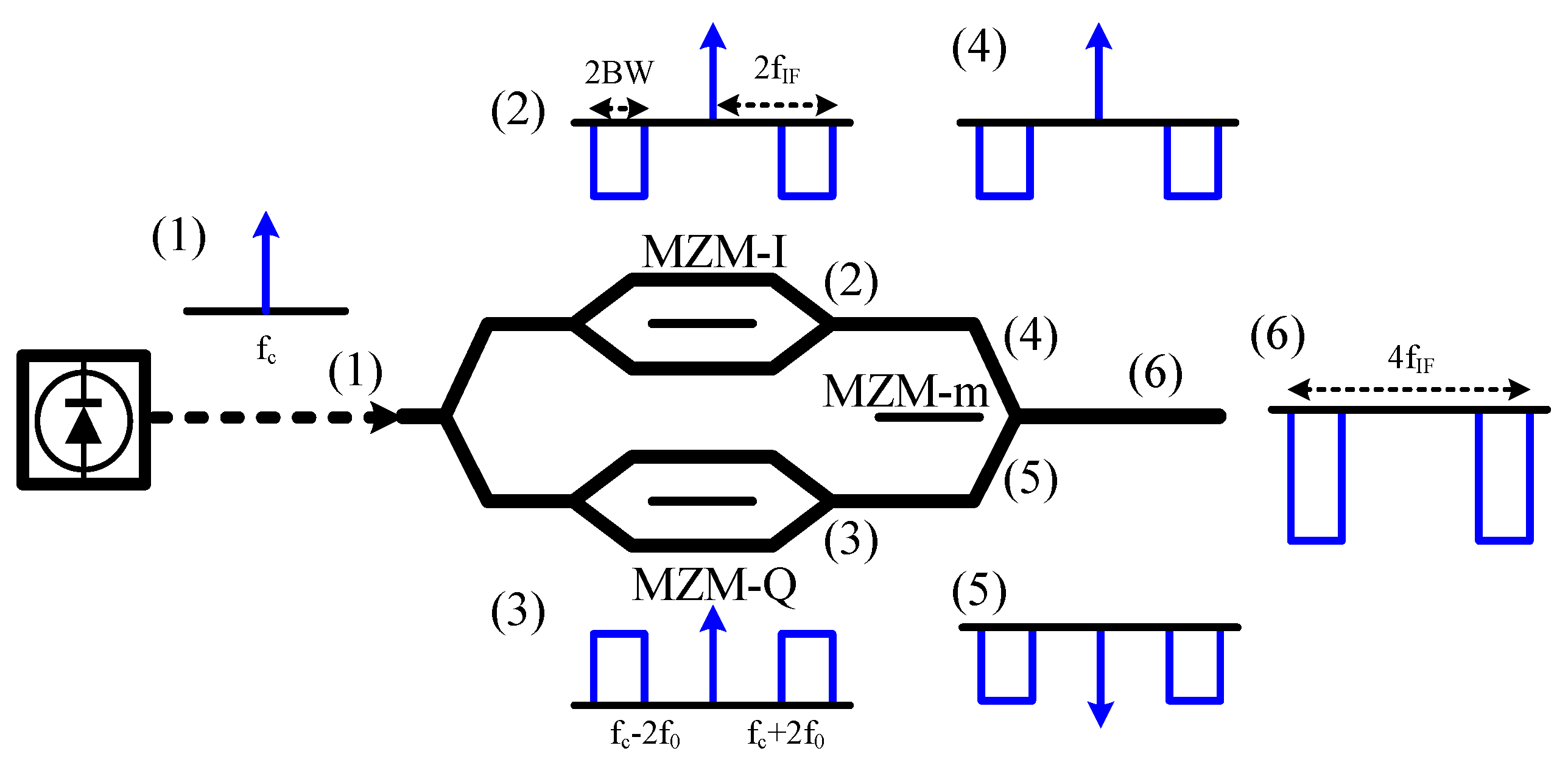
Figure 3 shows the principle of the quadrupled signal generation through a DPMZM using two signals which have a 90
phase difference.
As shown in
Figure 3, the DPMZM consists of three sub-MZMs, which are placed in two sub-MZMs (MZM-I and MZM-Q) on each arm of the main MZM (MZM-m). The output signals with a 90
phase difference are applied to MZM-I and MZM-Q, respectively. If the operation points of the two sub-MZMs (MZM-I and MZM-Q) are both at the full-bias point, the outputs of the sub-MZMs produce the optical carrier and even-order sidebands with a 180
phase difference ((2) and (3) of
Figure 3). In contrast, MZM-m should be biased at the null-bias point to minimize the signal amplitude at the carrier frequency ((4) and (5) in
Figure 3) [
25]. Therefore, the optical signal of the DPMZM output can be expressed as
where
m is the modulation index of the two sub-MZMs as
,
is the instantaneous frequency as
, and
means the
th-order Bessel function of the first kind. If the harmonics are higher than the 2nd-order under the conditions of the appropriate modulation index for generating a quadrupled signal, it can be negligible due to the relatively low amplitudes and Equation (
2) can be simplified as
The DPMZM output signal is branched through an OC for use in the transmitter and the receiver of the proposed architecture. One of the two-branched signals is used as a base signal for the de-chirping process in the receiver, and the other signal is transmitted to an MZM, which makes the conventional photonic-based FMCW radar as a pulsed radar. An MZM is an intensity modulator, which has a characteristic in which the intensity of the output optical signal varies depending on the applied voltage. Thus, by controlling the applied voltage of an MZM, the pulse-type output signal can be generated even though the applied optical signal is continuous. The output signal of an MZM,
, by a time-dependent applied voltage is
where
is the insertion loss of the MZM,
is the applied optical signal,
is the half-wave voltage of the modulator,
, and
are the applied voltage to each arms of the MZM, respectively [
26]. The pulse generating voltage,
, to the MZM can be expressed as
, if
and
is satisfied, Equation (
4) can be denoted as
According to Equation (
5), if the pulse generating voltage is set to zero, the output signal of an MZM becomes
. However, if the pulse generating voltage is changed to
, the MZM output signal is zero. Using this characteristic, a signal for a pulsed radar, which is known as the gated LFM signal, can be generated by the control of the applied voltage of an MZM, which produces by a GSG. Therefore, only if the applied voltage of the MZM is zero, the output signal of the MZM can be represented as
As can be seen from Equations (
3) and (
6), if the pulse generating voltage is zero, the output signal of the MZM has two frequency spectrum of
and
, which is the same characteristics of the output signal of the DPMZM. In addition, it is noted that the PRF of the pulsed radar is determined by the applied voltage signal; therefore, by controlling the GSG, the pulse waveform with a various PRF can be generated according to changes in the operating environment as shown in
Figure 2. In the extreme case, if the GSG generates only zero voltage for whole operating time, the proposed architecture can operate the same as the conventional photonic-based FMCW radar.
The output signal of the MZM is sent to a PD, which converts signals from the optical domain to the electrical domain. The signal converted into the electric domain through the PD has an instantaneous frequency of and it is confirmed that the center frequency and the bandwidth of the domain-converted signal are quadrupled compared with the center frequency and the bandwidth of the applied IF signal. Finally, the domain-converted signal is transmitted through the antenna to space for detecting a target.
If there exists a target, the echo signal reflected by a target is received through the antenna. The received signal enters an RF port of a PM, which modulates the optical signal from the DPMZM output as shown in
Figure 1. As represented in Equation (
3), the output of the DPMZM has two optical carriers at
and
and is modulated by the reflected echo signal, which has a frequency of
. Here,
is the time delay due to target reflection and the PM produces a serial of sidebands at both sides of the optical carrier separated by the amount of frequency of the received echo signal,
, and it shifted the phase by
[
27]. Therefore, the output of the PM,
, is expressed as
where
is the phase-modulation index and
is angular frequency of the received signal. By applying the Jacobi-Anger expansion, Equation (
7) can be rewritten as
Considering only the 1st-order coefficient of the infinity coefficient of the power series, Equation (
8) can be simplified as
The output signal of PM is connected to the input of a DOBPF. The purpose of the DOBPF is to extract the frequency spectrum difference from the phase-modulated signal by the reflected echo signal. Therefore, by blocking the other harmonics except for the components with a beat frequency, the output signal of the DOBPF,
, is expressed as
Each of the DOBPF output signals is injected into a BPD, which converts the signals from the optical domain to the electrical domain with suppression of the common-mode noise and reinforcement of the amplitude of signals, to extract the beat frequency, respectively [
28]. As shown in (ii) and (iv) of
Figure 2, the pulse signal by the MZM is transmitted to detect the target; however, the continuous LFM signal from the DPMZM output is applied to the receiver as the base signal for the de-chirping processing. Therefore, the beat frequency has three frequency components, namely, low-frequency, high-frequency, and time-varying-frequency components due to the frequency differences between the continuous LFM signal and the reflected echo signal. The low- and high-frequency components occur when the received pulse signal exists, however, the time-varying-frequency component is generated when there exists only the base signal. Because only the low-frequency component is valid, in order to eliminate the time-varying frequency component, the beat frequency is extracted with synchronous at the same period as the MZM control signal of the GSG. Furthermore, since the amplitude of the high-frequency component is small enough to negligible, it can be filtered by the ADC without the electrical low-pass filter in contrast to the conventional structure. Therefore, the beat frequency
can be obtained.
To evaluate the fundamental performance of the proposed pulsed radar system, it is necessary to measure the range resolution and the cross-range resolution. According to the beat frequency representation in Reference [
1], the range resolution,
is represented as
because the minimum identifiable spectral interval,
, is
, where
c is the velocity of light,
T and
B are the time period and the bandwidth of the pulse signal, respectively. According to Equation (
11), it is clear that a broadband signal is required for obtaining a high range resolution of the target. However, as distinct from the range resolution, the cross-range resolution is determined by the specification of the antenna and the distance to the target. As for considering Fraunhofer distance [
29], if the target is in the far-field, the cross-range resolution can be expressed as
where
is the cross-range resolution,
R is the distance from the receiving antenna to the target, and
is the 3-dB beamwidth of the antenna. If
is small enough, the cross range resolution will be simplified as
.
3. Experimental Setup and Results
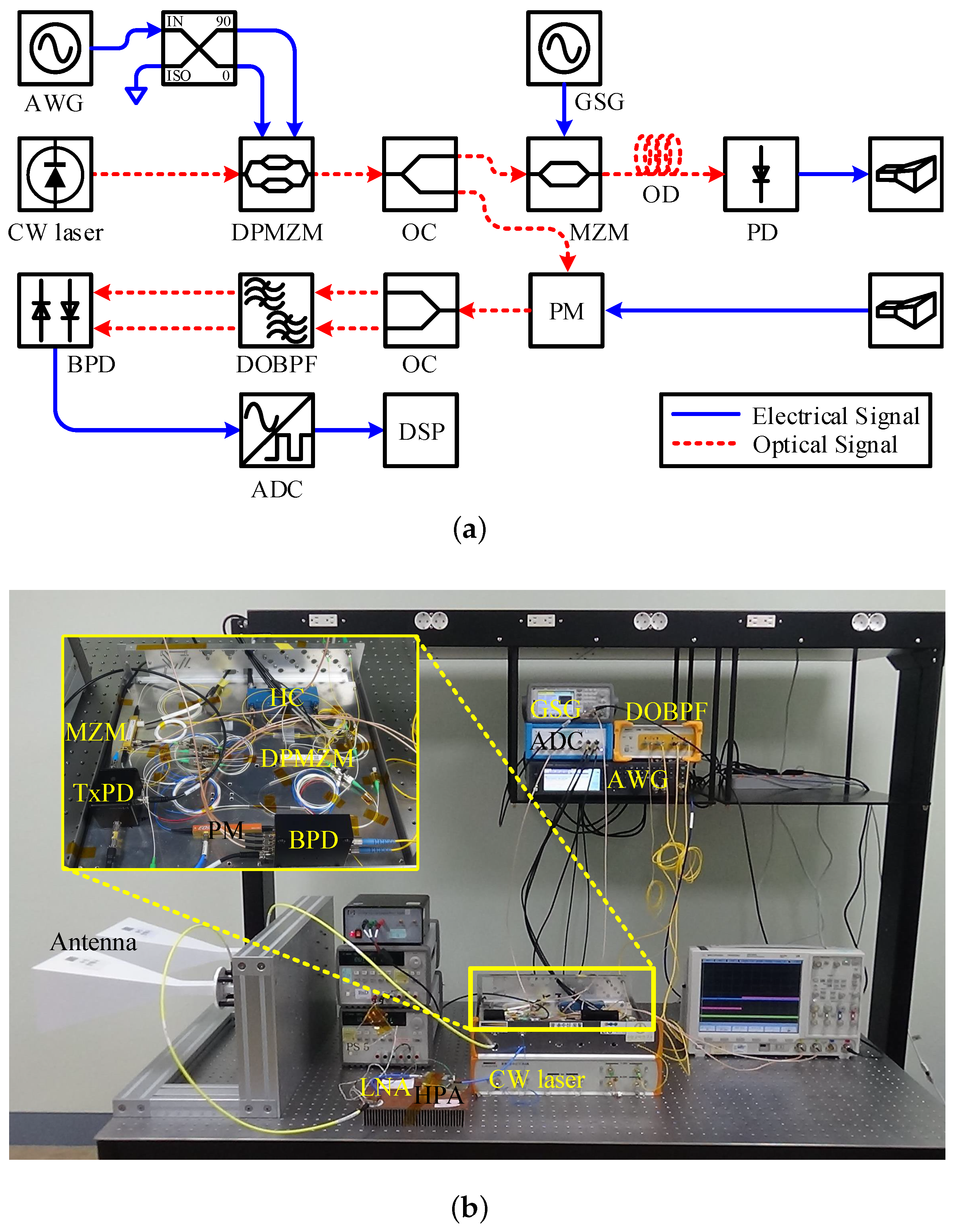
Figure 4 shows the prototype of the proposed photonic-based pulsed radar architecture for conducting the indoor experiment. Considering the blind region and indoor testing circumstances, different from
Figure 1, the transmitting and receiving antennas are separated without a circulator to possibly detect nearby targets. In addition, regarding the input frequency range of an ADC, the optical delay (OD) line is employed to increase the beat frequency between the reference signals and the received signals.
In
Figure 4a, the output power of the CW laser source (TeraXion Inc.: Quebec city, QC, Canada, PS-NLL-1550) is set 18 dBm at a wavelength of 1550 nm for the indoor test. The prototype of the proposed
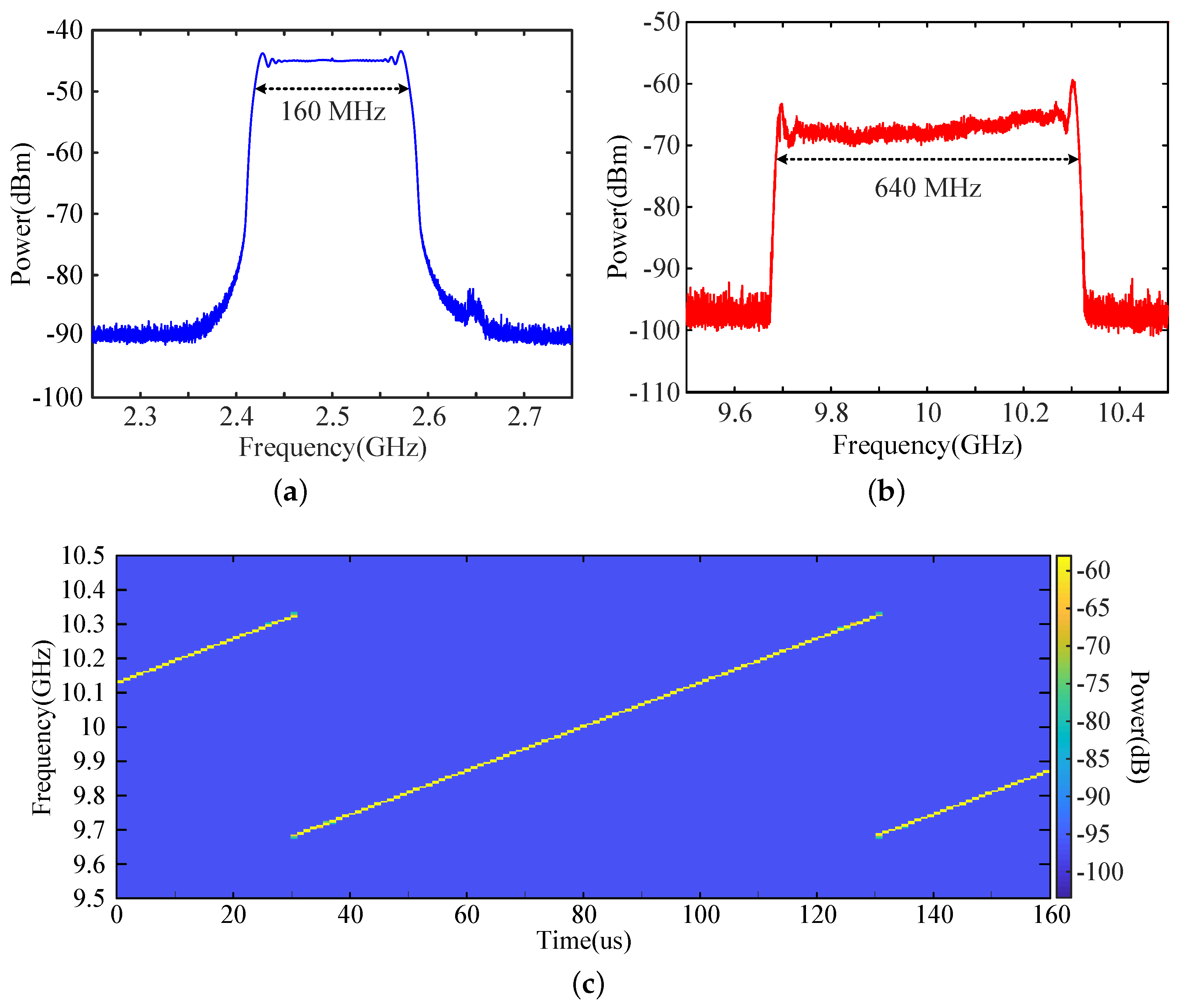
X-band photonic-based pulsed radar is designed operating at a center frequency of 10 GHz and a bandwidth of 640 MHz. For operating the prototype, the IF-band signal with a bandwidth of 160 MHz, the center frequency of 2.5 GHz, and a PRF of 10 kHz is generated by the AWG (Keysight: Santa Rosa, CA, USA, N5182B). The electrical characteristics of the DPMZM (Fujitsu: Tokyo, Japan, FTM7962EP), which is used for IF-band signal modulation, are a half-wave voltage(
) of 3.5 V and a 3-dB bandwidth of 22 GHz. The OC with 10:90 coupling ratio is applied to split the output signal of the DPMZM and 10 % optical power is used for the transmission considering the limited indoor testing circumstance. The upper lane of the OC in
Figure 4a is connected to the MZM (SDL Inc.: Los Angeles, CA, USA, IOAP-MOD9140-F-F-0), which has an insertion loss of 3.5 dB and a half-wave voltage is 4.9 V at 10 GHz, for generating the gated LFM signal, which has a pulse repetition frequency of 1 kHz with a 10 % duty cycle. The output signal of the MZM is sent to a transmitted PD (New Focus Inc.: San Jose, CA, USA, 1544-B), which has 3-dB bandwidth up to 12 GHz. The generated gated LFM signal is passed along the optical delay line of 33 m to increase the beat frequency considering the input range of the ADC and sent to a transmitting horn-type antenna (MTG Inc.: Chungnam, Korea, SGH-90) with a gain of 22 dB and 13
of beamwidth for target detection.
Describing the recevier of the proposed architecture, the signal reflected by a target is acquired by the receiving antenna, and it is amplified by a solid state amplifier (Narda West Inc.: Folsom, CA, USA, DBS-0618N727) with a gain of 43 dB, and sent to the PM (EO Space, PM-0S5-PFA-PFA), which has a bandwidth of 40 GHz. The 50:50 optical coupler is located after the PM as shown in
Figure 4a. Each of the two branches is connected to the DOBPF (Fiberpro Inc.: Daejeon, Korea, LE2000) to filter the required frequency components in Equation (
10), and the selected optical signals are sent to the BPD (Thorlabs: Newton, NJ, USA, PDB450C) to convert the signal from optical domain to the electrical domain. The domain-converted signal is sent to the ADC to convert for the digital signal, and the signal processing occurs at the DSP stage in real-time.
Figure 5 shows the characteristics of the transmitted signals.
Figure 5a,b are the max-hold spectra, which were measured by a spectrum analyzer, of the generated IF-band signal and the output signal of the DPMZM, respectively. As shown in
Figure 5a,b, both of the center frequency and bandwidth of IF-band signal were quadrupled through the DPMZM.
Figure 5c shows the spectrogram of the quadrupled LFM signal. According to
Figure 5c, the output signal of the DPMZM had a center frequency of 10 GHz and a bandwidth of 640 MHz with a repetition interval of 100 μs. It is confirmed that the IF-band signal quadrupling by the DPMZM was successful. If the IF signal with a higher center frequency and wider bandwidth can be applied to the DPMZM using a state-of-the-art AWG, the center frequency and the bandwidth of the quadrupled signal can be higher and wider, similar to previous studies in References [
11,
12,
21,
22,
23].
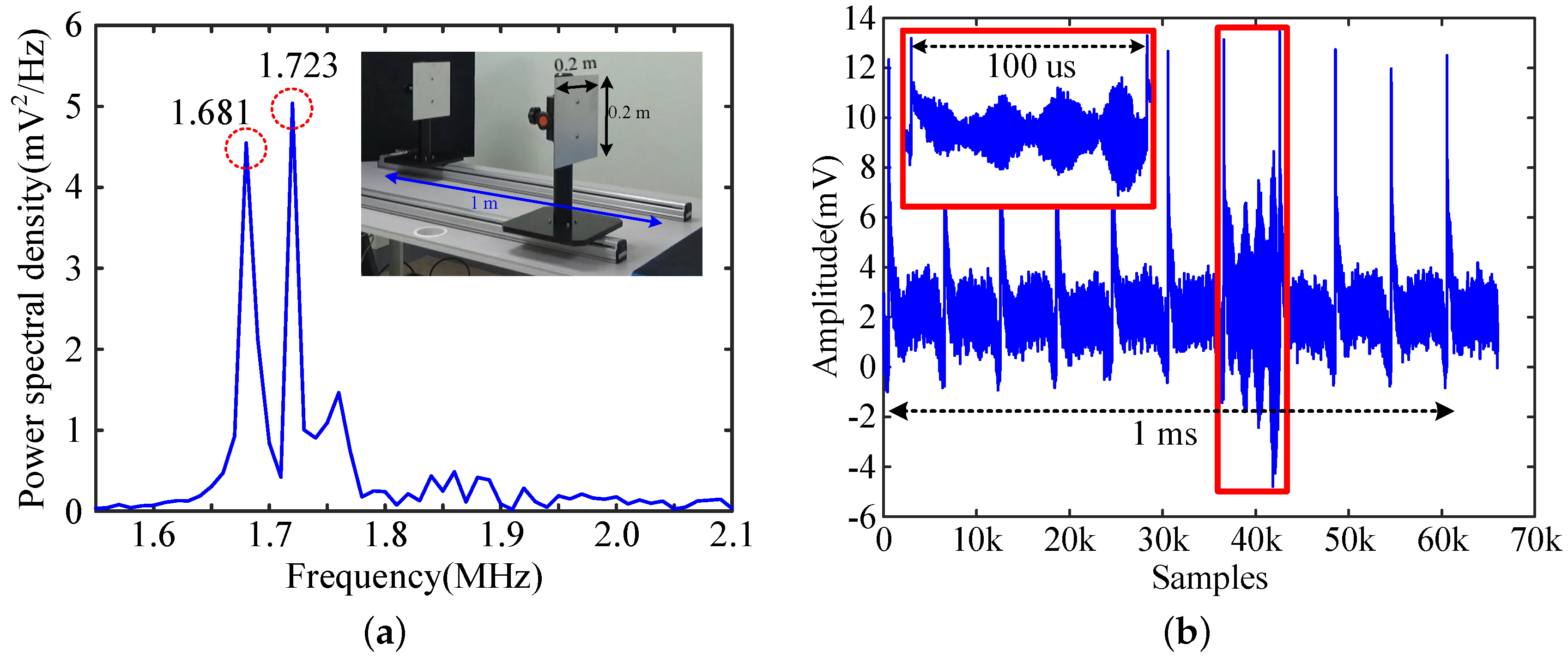
To evaluate the performance of the range and cross-range resolution of the proposed prototype, two metal plates with the height and width of 0.2 m each were placed at a distance of at least 2.5 m to a maximum of 3.5 m apart from the antennas. The spacing between two plates was set as 0.25 m, and the initial positions were located at both ends of the rails with each other as shown in the sub-figure in
Figure 6a. The graph in the
Figure 6a is the power spectral density of the beat frequency, which is caused by two metal plates and there are two clearly distinguishable peaks at 1.681 MHz and 1.723 MHz, respectively. According to Equation (
11), the calculated distance between the two targets is 0.984 m, which is quite similar to the real value and corresponds to the frequency differences between the two peaks. As seen in
Figure 6b, the de-chirped signal is converted to a digital signal in the time domain with a sampling rate of 60 MSa/s. Each of the de-chirp signal has the same repetition frequency as the PRF of the IF signal. It should be noted that one of the pulse train, which is enlarged and emphasized in red box in
Figure 6b, has the different from the others because it is produced by the beating between the transmitted pulse signal and the base signal in the PM. Furthermore, as seen in
Figure 3, the gated LFM signal, which is generated by the MZM, is effectively produced and it is confirmed that the proposed photonic-based radar architecture operates as a pulsed radar.
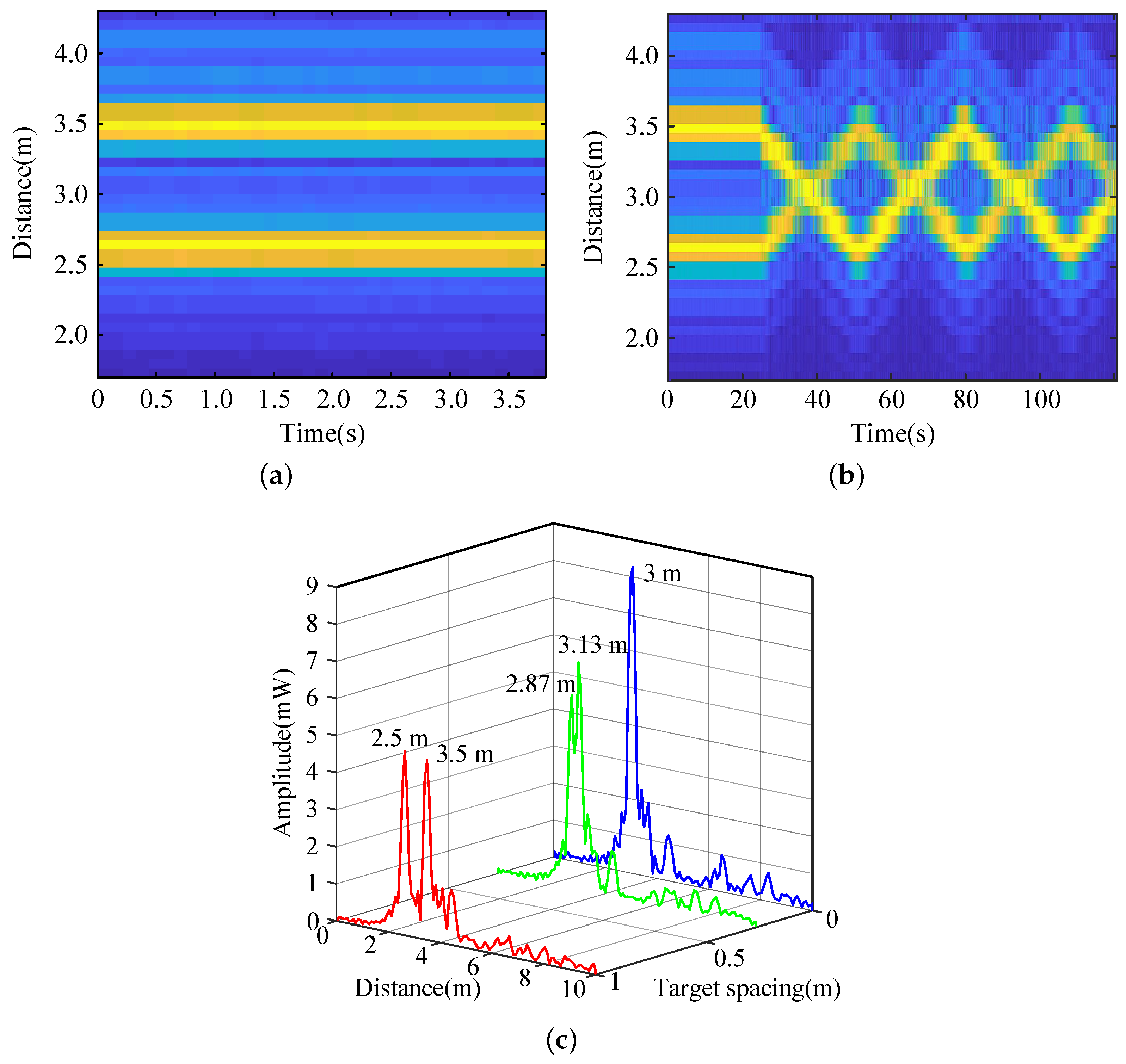
Since radars should be able to detect a moving target as well as a fixed target, the additional indoor experiments were conducted using two moving targets to examine the performance the tracking the movements of two targets in real-time.
Figure 7 shows the target history and the high-resolution range profiles (HRRP) of two moving targets. The initial position of two targets and the variation of positions of two targets are shown in
Figure 7a,b, espectively. In
Figure 7b, the motion of two target is described as follows: two targets moved at the same speed in opposite directions and remained stationary for a while at the end of rails for resuming the movement to the opposite directions. The HRRP at the initial positions of the two targets 2.5 m and 3.5 m from the receiving antenna is shown by the red line in
Figure 7c. The blue line in
Figure 7c shows the HRRP when the positions of the two targets were at the same position from the receiving antenna. It is noted that if two targets existed at the same distance from the receiving antenna, as in case of the blue line, the signal reflected by the targets had a larger amplitude, as reflected in the only one larger target.
If two metal targets were located at the minimum detectable distance to be separated, the HRRP is represented in green line in
Figure 7c. As shown in the green line in
Figure 7c, when two targets are located at 2.87 m and 3.13 m from the receiving antenna, respectively, which is 0.26 m apart from each other, the two targets can be distinguished. According to Equation (
11), the theoretical range resolution for detecting two targets separately is 0.23 m. Therefore, it is confirmed that the actual range resolution was quite close to the theoretical range resolution.
In order to examine the cross-range resolution, two targets have to be in the same distance from the receiving antenna. As can be confirmed in
Figure 7b, when the two targets were located at the same distance from the antenna, it is 3 m distance from two targets to the antenna. According to Fraunhofer’s distance, the minimum distance, which satisfied the far-field condition, from the antenna to the target is 2.6 m. The calculated Fraunhofer distance of the system is closer than the distance when two targets are located at the same range from the antenna, therefore, it can be assumed that two targets exist in far-field. In far-field conditions, through Equation (
12), the cross-range resolution can be obtained as 0.68 m, which is quite inferior compared with the range resolution because of the wide beamwidth of the antenna. Consequently, because the separation of the two targets is more affected by the range resolution than the cross-range resolution considering the antenna beamwidth used in this experiment, the two targets can be recognized separately due to the difference in the distance produced as the targets movement.
In order to compare the characteristics of the proposed photonic-based pulsed radar architecture with the results of the previous studies,
Table 1 summarizes the main characteristics of the previously studied photonic-based radar. As can be seen from
Table 1, it can be seen that the proposed pulsed radar architecture has the significantly broad bandwidth of the transmitted signal than the signal bandwidth of the previous photonic-based radar with MLL research results. The bandwidth of the experimental result is less than 1 GHz, which is narrower than that of the previously studied CW laser-based research result, but this result is due to the narrow bandwidth of the IF signal generated by the AWG. If the bandwidth of the IF signal becomes several GHz as in the previous study, it is also possible to generate a wideband signal similar to the previous study result in the photonic-based pulsed radar structure proposed in this paper. In addition, maximum detectable range in
Table 1 is definitely depends on the RCS of the target and the transmit power. Due to the limitations of the indoor test circumstance, the indoor experiments were conducted within several meters by adding attenuators to reduce the transmit power. If eliminate the use of attenuators and replace the high power amplifier at the transmitter with Qorvo Inc.: Greensboro, NC, USA, TGA2704-SM model, the maximum detectable range can be obtained as shown in
Table 1. In
Table 1, maximum range refers to the distance used in the experiment if the maximum detectable range is not disclosed in the papers. If the maximum detectable range is not disclosed among the previous research results compared in
Table 1, the maximum range can be inferred through information such as an RCS of the used target, the transmit power, and total system loss of the radar system. However, if there is not disclosed information about the radar system, the detectable range must be inferred through the types of radar. In general, the maximum detectable range of an FMCW radar is relatively small than the maximum range of a pulsed radar [
13]. In this paper, the maximum detectable range was calculated by assuming that RCS is 1
0 dBsm) and the maximum range can be increased if the RCS of the target is assumed more than 1
.


