1. Introduction
Offshore wind power is inevitably becoming an important clean energy source in coastal areas of China due to its advantages of high wind speed, low turbulence intensity and no occupation of land area [
1]. However, compared with onshore wind turbines, offshore wind turbines face a more complex environment. Sustainable wind and wave forces on the structure of wind turbines are prone to vibration problems, which not only affect the normal operation characteristics of offshore wind turbines and reduce the output power quality, but also increase the fatigue load of the components of the wind turbines and shorten the life of the units. Therefore, when analyzing the vibration characteristics of offshore wind turbines, the effects of wind and wave on them should be fully considered.
The research on the influence of wind on the vibration characteristics of wind turbines shows that with the continuous expansion of wind turbine blades, wind shear and tower shadow cause a great imbalance of the wind speed distribution in the rotating plane of wind turbines, which causes the aerodynamic load of wind turbines to pulsate mainly at the 1P frequency [
2], and the aerodynamic torque to pulsate mainly at the 3P frequency [
3]. The term ‘P’ refers to per revolution and indicates multiples of the rotational frequency of the turbine. In addition, due to wind shear and tower shadow, the periodic aerodynamic load acts on the tower, which makes the tower fore-aft moment fluctuate, and then the fore-aft vibrations of the tower occur.
There have been many achievements in the research on vibration reduction of onshore wind turbines and the pitch control methods, especially the individual pitch control methods, which have been proved to be common and effective methods for wind turbine vibration reduction. In general, such researches can be summarized into three groups. First, some literature concentrates on the tower vibration reduction by pitch control methods. Based on analyzing the causes of tower vibration, the optimization control strategy is proposed by increasing the tiny pitch angle in the pitch control system, which can increase the aerodynamic damping of the tower. The proposed strategy can effectively reduce the fore-aft vibration and torque of tower, and has little influence on the power [
4]. Lio et al. [
5] presented a method to estimate the tower fore-aft velocity using the measured data of blade load sensors and a control strategy of increasing tower damping based upon an individual pitch control architecture. Second, a number of pitch control strategies for structural load control in blades or rotor have been proposed. It was found that the individual pitch control method is very effective for smoothing the fluctuation of the blade root load of wind turbines in [
6,
7]. Coral-Enriquez et al. [
8] provided two individual pitch control schemes to attenuate the main periodic load components of blade flap-wise and hub yaw/tilt-wise bending moments in wind turbines under varying-frequency conditions. Jones et al. [
9] pointed out the limitations of conventional individual pitch control based on blade root load feedback, and then presented an additional cascaded feedback controller based upon a local blade inflow measurement on each blade to better reduce blade root flap-wise load. Ossmann et al. [
10] designed an individual blade pitch control law using multivariable linear parameter-varying control techniques to reduce the structural loads both on the rotating and non-rotating parts of the turbine. Fitzgerald et al. [
11] provided a novel individual pitch control strategy using a wavelet linear quadratic regulator control algorithm to reduce blade vibration. Civelek et al. [
12] proposed a new fuzzy logic proportional control approach applied to individual pitch angles, which can mitigate the moment load on the blades and tower to a minimum possible value while keeping the output power of wind turbines at a constant value. He et al. [
13] investigated the combined pitch and trailing edge flap control including an individual pitch control loop and a trailing edge flap control loop for load mitigation of wind turbines. Mohammadi et al. [
14] proposed a new control method by using two supplementary controllers an internal model controller with an adaptive algorithm and a standard individual pitch controller to suppress the tower vibrations and to reduce the fatigue loads of the wind turbine, with the internal model controller reducing the tower vibrations and the standard individual pitch controller reducing the fatigue loads of the wind turbine. The last group of literature look into pitch control methods to restrain the fluctuation of aerodynamic torque and output power. Zhang et al. [
15] used the individual pitch control method to reduce the 3P fluctuating component of wind turbine output power, which is validated in different wind speed scenarios. Dou et al. [
16] proposed a variable pitch control strategy, which periodically adjusts each blade’s pitch angle by measuring the azimuth signal and distributing the azimuth weight coefficient to reduce the 3P pulsation component of wind turbine torque. Imran et al. [
17] designed multivariable disturbance observer based linear controllers which can be used with individual pitch control with the objective of reducing output power fluctuation, tower oscillation and drive-train torsion by using optimal control theory. Tian et al. [
18] proposed a new individual pitch control strategy for three-bladed wind turbines to reduce the 1P fluctuation component in the aerodynamic loads and the multiples of the 3P fluctuation component in the aerodynamic torque caused by wind shear and tower shadow.
However, at present, the effect of waves on wind turbines is mainly focused on the dynamic response, fatigue load, ultimate load, etc., of the foundation of offshore wind turbines under wave force [
19,
20,
21,
22]. The research object of the above research is only the offshore wind turbine tower. Nowadays, few studies have analyzed the effect of waves on blade load and wind turbine aerodynamic torque in the mechanism. Hemmati et al. [
23] studied vibration control of offshore wind turbines induced by multi-hazard excitations and established a model consisting of the entire offshore wind turbine foundation and tower controlled by tuned liquid column dampers considering nonlinear soil pile interaction, which is subjected to wave, wind, and seismic loading. Numerical analysis results demonstrate the effectiveness of the optimal tuned liquid column dampers in reducing the fore-aft vibration of the tower. Namik and Stol [
24] applied individual blade pitch state space control and disturbance accommodating control that reject wind speed perturbations on a 5 MW wind turbine mounted on the barge and tension leg floating platforms for performance comparison in the above rated wind speed region, and simulation results show that individual blade pitch state space control can significantly reduce tower load. Namik and Stol [
25] also presented the development of a periodic state space controller that utilizes individual blade pitching to improve power output and reduce platform motions of floating wind turbines in the above rated wind speed region. Sarkar et al. [
26] proposed a wavelet multi-resolution based individual pitch control strategy for spar-type floating offshore wind turbines and investigated the performance of the proposed strategy under joint wind-wave-current loads considering the interaction between wave and current. Simulation results show that the aerodynamic loads can be decreased with this control strategy, which in turn reduces vibration in tower fore-aft and platform pitching motion of the wind turbine. However, in these studies, the mechanism of how waves affect the load of wind turbines and aerodynamic torque is not systematically analyzed.
Therefore, on the basis of studying the wind model and the influence of wind on the vibration characteristics of wind turbines [
4,
5], this paper concentrates on the impact of waves on the vibration characteristics of them and proposes an improved individual pitch control. The novelty of this study can be summarized into two parts. On the one hand, the effects of waves on wind turbine towers, blade load and aerodynamic torque are investigated by theoretical analysis and simulation. On the other hand, an improved individual pitch control strategy is proposed to reduce the fluctuation of the aerodynamic load and torque of the wind turbine under wind and waves. Based on the vibration acceleration signal of the tower top, the collective pitch angle can be adjusted to reduce the fluctuating component related to the hydrodynamic frequency in the aerodynamic load and torque. Then, the pitch angle of each blade is adjusted based on the output power of the wind turbine and the azimuth angle of the blade to further reduce the fluctuation of the aerodynamic load and torque of the wind turbine caused mainly by wind shear and tower shadow.
The rest of this paper is organized as follows: The mathematical model of a wave is established and the calculation method of wave force is presented in
Section 2. The influence of waves on load and aerodynamic torque of wind turbines is analyzed in
Section 3.
Section 4 proposes a pitch angle control strategy for reducing load and torque pulsation caused by wind and wave.
Section 5 presents the simulation results and
Section 6 draws the conclusions.
2. Wave Model and Wave Force Calculation
In this paper, the vibration characteristics of offshore wind turbines under the influence of wind and waves are mainly studied. As is shown in
Figure 1, the influence factors of wind include wind shear, tower shadow and turbulent wind, and the influence factors of waves include wave height and wave period. Some studies focus on the vibration characteristics of wind turbine under the influence of wind, especially the impact of wind shear and tower shadow [
2,
3]. To suppress the wind turbine vibration caused by wind, several control strategies have been studied [
5,
8,
14,
17]. The influence of waves on the vibration characteristics of the wind turbine needs further study, and the control strategy to suppress the vibration of the wind turbine caused by wind and waves needs to be proposed. To this end, a wave model and wave force calculation are studied.
There are two main research directions in the theory of wave modeling. One is regular wave theory, which uses hydrodynamics to reveal the motion of material particles in liquid. The other is random wave theory, which shows the distribution characteristics of wave energy in sea waves by studying the randomness of sea surface fluctuations. The random wave theory is derived from the former one.
2.1. Regular Wave Model
In the regular wave model, the wave theory based on stream function takes into account the nonlinearity of waves and has many advantages. It can be widely used and extended to any order, which has good fitting conditions and can take into account the effect of ocean currents. It can simulate the near-breaking nonlinear wave in a shallow water well. The coordinate system is established based on a regular wave diagram, as is shown in
Figure 2. The intersection point between the axis of the cylinder and the mean water level (MWL) is the coordinate origin, the direction of wave propagation is set to the
x axis, and the
z axis is vertical upward. Moreover,
h is the water depth,
D is the diameter of the tower, and
is the height of the wave surface.
The wave model based on stream function can be expressed as [
27]:
where
X(
n) is the coefficient of higher order perturbation term;
L is the wavelength;
T is the wave period.
At the same time, the wave has periodicity both in time and space, which satisfies the boundary conditions: , .
2.2. Random Wave Model
In fact, the wave situation is random, and the direction, size and period of the wave are irregular. The power spectrum of the wave is developed to reflect the energy distribution characteristics of random waves at different frequencies, and is an important means of describing random waves. At present, the commonly used wave spectrum includes Pierson Moskowitz (P–M) spectra, JONSWAP spectra [
23,
28,
29]. They use semi-theoretical and semi-empirical formulas to describe the power spectral characteristics of random waves based on the observation of an actual wave. The one-sided DNV (Det Norske Veritas) version of the P–M spectra [
28] is used in this paper.
where
f is the wave frequency in cycles per second;
Hs is the significant wave height, and
Tz is the zero up crossing period;
Sη is the single-sided P–M sea surface elevation spectrum.
The interval between two adjacent upward zero-crossing points recorded by the wave surface is usually defined as a period. From the P–M spectrum, the relationship between the peak spectrum period and zero up crossing period satisfies [
30]
where
Tp is the peak spectral period.
2.3. Calculation of Wave Force
The diameter of the offshore wind turbine tower is relatively small compared with the wave length. According to Morison’s theory, the wave force acting on the whole tower in direction
x,
Fx, can be expressed as [
31]
where
is the velocity of the fluid particle in direction
x at time
t;
is the acceleration of the fluid particle in direction
x;
is the density of seawater;
is the hydraulic resistance coefficient, which is usually set as 0.7–1.2;
is the hydraulic inertia force coefficient, which is usually set as 1.7–2.0.
According to Equation (4), the horizontal wave moment is mainly related to variables and . Therefore, the wave period and wave height play a decisive role in the wave force acting on the offshore wind turbine structure.
3. Effect of Wave on Load and Aerodynamic Torque of Wind Turbines
In reality, sea waves are random and can be seen as the superposition of numerous regular waves with different amplitudes and frequencies. Therefore, to quantify the effects of random wave on the load and aerodynamic torque of wind turbines, we start with the evaluation of effects of regular waves.
3.1. Effect of Regular Waves on Tower
The forced vibration of a structure will occur under the action of external forces. The forced vibration equation of the single degree of freedom system is expressed as follows:
where
m is the mass of the system;
k is the bending stiffness;
c is the damping coefficient;
u is the displacement;
is the velocity;
is the acceleration;
p(
t) is the load varying with time.
When the load
p(
t) is arbitrary periodic, it can be represented as a Fourier series as follows:
where
a0,
an,
bn are the coefficients and
is the frequency of the
n-th external load.
The steady-state response of the system can be expressed as follows [
32]:
where the frequency ratio is
;
is the natural frequency of the system;
is the ratio of the system damping to the critical damping.
In Equation (7), the vibration frequency of the system is the same as that of the external load, but there is a certain phase difference [
32]. Therefore, when the waves periodically act on the tower, the fluctuating component of the hydrodynamic frequency in the load on the tower at the MWL will increase.
The part of the tower above the elevation of the wave surface is not directly affected by the wave, but it also faces the impact because the low frequency vibration caused by the wave will run through the whole tower system due to the small damping matrix term of the steel tube tower structure. The relationship between the bending moment at the bottom of the tower
and the horizontal displacement at the top of the tower
satisfies
where
K is the bending stiffness of the tower, the bending stiffness is the resistance of a member against bending deformation; and
H is the height of the tower.
Therefore, the top displacement and the bottom moment of the tower have the same waveform, that is, the vibration caused by wave will be transmitted from the bottom of the tower to the top of the tower. During this process, the vibration energy will be weakened because of the damping effect, but the vibration frequency will remain unchanged.
3.2. Effect of Regular Waves on Blade Load and Aerodynamic Torque
The relative wind speed on the wind turbine blade is the superposition of the wind speed and the blade’s own motion speed. That is, when the tower top moves forward and backward, the relative wind speed of the blade will increase or decrease accordingly. The wind speed under the influence of tower motion can be expressed as
where
is the original wind speed;
is the tower top motion speed in the direction of wind speed. In the area where the wind blows, it is generally considered that the direction of wave propagation is consistent with the wind direction. Therefore, in this paper, we assume that the wind load and wave load acting on the wind turbine and the tower are in a consistent direction.
The aerodynamic load of the wind turbine is directly related to the relative wind speed of the blade, and the former will change with the latter. When the load of the wind wheel acting on the tower changes, the tower deforms to varying degrees, which affects the relative wind speed. Therefore, there exists a dynamic coupling effect between the wind wheel and the tower during the whole vibration process of the wind turbine.
Without considering the blade-tower coupling effect, the root shear force of the rotating blade is the sum of the total inertial force of the blade, which can be expressed as [
33]
where
is the blade root shear force;
is the mass of the blade element, and
is the acceleration of the blade element.
When considering the blade-tower coupling effect, the effective shear force of a blade can be written as [
34]
where
is the acceleration of the tower top. Applying Equation (10) to Equation (11), we have
where
MB is blade mass.
In Equation (12), the inertia effect of the tower top on the blade is considered, and the coupled equation can be decoupled by the method of additional mass in the process of solving. So, the shear force of a single blade is affected by its own mass distribution and acceleration, as well as the acceleration of the tower top. In other words, when considering the blade-tower coupling effect, the vibration of the tower top caused by the wave will add a shear force of the same frequency to the blade root in the same direction.
The relationship between the shear force of the blade root flap-wise direction
and the blade root flap-wise load
can be written as [
35]
where
r0 is the hub radius;
R is the wind wheel radius;
r is the distance between the blade element and blade root.
The change of the relative wind speed of the blade will lead to the obvious change of the aerodynamic torque produced by the wind wheel.
where
is air density;
CT is the torque coefficient;
is wind wheel speed, and
is pitch angle.
Linearize Equation (14) near any operating point and the following equation is obtained
where
,
,
,
,
are linear incremental functions of aerodynamic torque, original wind speed, the tower top motion speed in the direction of wind speed, rotor speed and pitch angle respectively;
,
,
are the partial derivatives of aerodynamic torque at the linearization point of wind speed, wind turbine speed and pitch angle.
It can be seen from Equations (13) and (15) that the wave will result in the hydrodynamic frequency fluctuating component in both the blade root load and the aerodynamic torque, and the influence of the wave on aerodynamic torque is particularly noticeable.
The influence of a regular wave on load and aerodynamic torque of wind turbines is extended to that of a random wave on load and aerodynamic torque of wind turbines. A random wave can be seen as the superposition of numerous regular waves with different amplitudes and frequencies [
36], therefore, the load and aerodynamic torque generated by the random wave acting on the wind turbines can be regarded as the superposition of the load and aerodynamic torque generated by several regular waves acting on the wind turbines. The vibration mechanism is consistent, but the hydrodynamic frequency is extended from a single value to a range.
4. Pitch Angle Control Strategy for Reducing Load and Torque Pulsation
The blades of wind turbines are affected by the beating waves transmitted from the tower and produce a low frequency vibration related to the hydrodynamic frequency. In practice, wind shear and tower shadow will make the wind speed unevenly distributed in the rotating plane of the wind wheel, resulting in 1P aerodynamic load pulsation and 3P aerodynamic torque pulsation. In this case, it is very important to adjust the blade pitch angle to improve the aerodynamic characteristics of the blade and the output power quality of the wind turbine from the source.
When the wave hits on the tower, the tower vibrates with a certain frequency, hence the relative wind speed changes correspondingly. Because the calculation of aerodynamic torque is directly related to the relative wind speed, the wave will have a certain impact on the aerodynamic torque, which is expressed in Equation (15). To reduce the fluctuating component of hydrodynamic frequency in aerodynamic torque, an additional torque
can be added to the original aerodynamic torque, as shown in Equation (16), to suppress the aerodynamic torque disturbance caused by
.
The additional aerodynamic torque component is realized by adding the pitch angle value on the basis of the reference value of the collective pitch angle
. With the increase of pitch angle, the aerodynamic force captured by the blade decreases, and the aerodynamic torque decreases, and vice versa, showing a negative correlation. Therefore, the specific adjustment of pitch angle can be written as
where,
is control gain value.
Combining Equations (15) and (17), the adjusted aerodynamic torque can be expressed as
so,
. Because of the non-computability of the ratio, the value of
can be determined through continuous experiments in the simulation.
Because it is easy to measure the acceleration of the tower, the tower speed can be obtained indirectly through the vibration acceleration of the tower in practical application [
3]. So that
On the basis of collective pitch control, the pitch angle of each blade is adjusted independently. Because the aerodynamic torque is directly related to the output power, and the aerodynamic torque cannot be measured directly, in this paper, the low-pass filter is used to filter the 3P fluctuating component of the output power, which is converted into pitch angle adjustment signal
by the PI controller. Then by combining the azimuth angle signal of each blade
(
i = 1, 2, 3), the pitch angle adjustment signal of each blade
is obtained [
37], which is finally superimposed to the collective pitch angle
. By using the proposed pitch angle control strategy, the fluctuating component of hydrodynamic frequency in aerodynamic torque is reduced, as well as the 1P aerodynamic load fluctuation and 3P aerodynamic torque fluctuation of the wind turbine. The block diagram of variable pitch control is shown in
Figure 3.
The transfer function of the low-pass filter in
Figure 3 can be written as
where
s is the Laplace operator, and
λ0,
λ1,
λ2,
μ0,
μ1,
μ2 are transfer function parameters.
The proportional and integral coefficients of the PI controller can be expressed as
Kp and
Ki, so
can be expressed as
where
P3P(
t) is the 3
P fluctuating component of the output power filtered by the low-pass filter.
Wind shear and tower shadow make the wind speed captured by each blade in the process of rotation closely related to the azimuth angle signal
of the blade [
38]. If the pitch angle of each blade changes periodically with the blade azimuth angle, the load fluctuation caused by the non-uniform wind speed will be effectively suppressed. The pitch angle of each blade can be written as
5. Simulation Study
Simulation analysis was carried out on GH Bladed. In order to better verify the influence of sea wave on the vibration characteristics of wind turbines and the effectiveness of the proposed pitch angle control strategy, a 5 MW single pile, three-blade, variable-speed, constant-frequency wind turbine was selected as the simulation unit. The 1P frequency of the wind turbine is 0.2268 Hz, and the 3P frequency of the wind turbine is 0.6804 Hz. Assume that the water depth is 25 m, the hydrodynamic drag coefficient
is 1, and the hydrodynamic inertia force coefficient
is 2. When wind shear and tower shadow are considered, the wind shear coefficient is 0.11, and the tower diameter correction factor is 1. At this time, the wind turbine operates at the rated state, and the limits of pitch angle amplitude and change rate are set to [0°, 90°] and [−8°/s, 8°/s] [
9], respectively. Because the 3P frequency of the wind turbine in this paper is 0.6804 Hz, the frequency range of the low-pass filter is set to 0–1 Hz, and the corresponding transfer function coefficients are
λ0 = 0.067,
λ1 = 0.134,
λ2 = 0.067,
μ0 = 1,
μ1 = −1.143,
μ2 = 0.413, respectively.
5.1. Simulation and Verification of the Effect of Waves on Wind Turbine
5.1.1. Simulation and Verification of the Effect of Regular Waves on Wind Turbine
In order to verify the existence of hydrodynamic frequency fluctuation components in wind turbine tower load, blade load and aerodynamic torque, the wind turbine load and aerodynamic torque with and without regular wave are simulated, as is shown in
Figure 4,
Figure 5 and
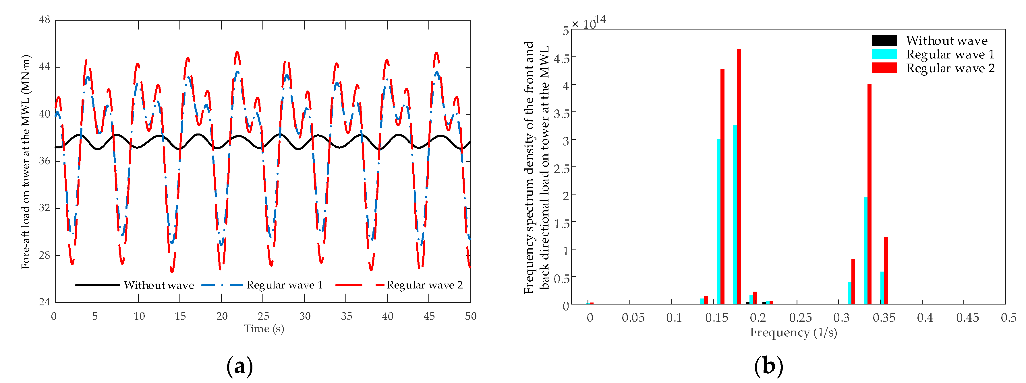
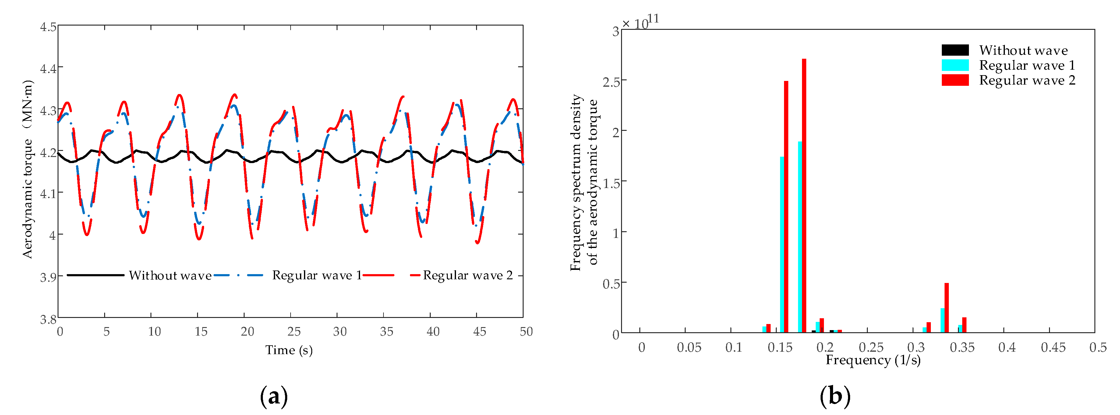
Figure 6. ‘Without wave’ refers to the operation of offshore wind turbines in a wind-only environment, while ‘Regular wave 1′ and ‘Regular wave 2′ refer to the operation environment of offshore wind turbines containing both wind and regular wave. For simplification, wind shear and tower shadow are not considered here. In the simulation, the wind speed at the hub center is constant at 14 m/s, and the wind and wave are in a consistent direction. In ‘Regular wave 1′, the wave height is 2.0 m, and the wave period is 6 s. In ‘Regular wave 2′, the wave height is 2.4 m, and the wave period is 6 s.
From
Figure 4, the hydrodynamic frequency at 0.167 Hz directly impacts the tower and causes the low frequency oscillation at 0.167 Hz and 0.33 Hz (two times hydrodynamic frequency). According to statistics, the peak spectrum period of wave in China offshore is about 3–10 s, i.e., in the range of 0.1–0.33 Hz [
39,
40]. Therefore, it is very easy to cause low-frequency vibration of the tower in the direction of current. If the hydrodynamic frequency is similar to the vibration frequency of the tower, it will cause resonance.
From
Figure 5, when the blade-tower interaction is considered, the vibration of the top of the tower caused by regular wave will increase the blade root flap-wise load fluctuations at the hydrodynamic frequency. However, the fluctuation of blade root flap-wise load at 1P frequency is slightly reduced under the influence of regular waves. In general, the effect of wave on blade root load is small due to the damp effect of tower and wind wheel. From
Figure 6, when regular waves act on the wind turbine, a large fluctuating component of hydrodynamic frequency will be produced in the aerodynamic torque.
From
Figure 4,
Figure 5 and
Figure 6, it is found that the greater the wave height of the regular wave, the greater the impact of the wave on the vibration of the wind turbine and the tower, and the greater the fluctuation of the fore-aft load on tower at the MWL, blade root flap-wise load and aerodynamic torque.
5.1.2. Simulation and Verification of the Effect of Random Waves on Wind Turbine
The influence of random waves on the vibration characteristics of wind turbines is verified under constant wind conditions. In this case, the wind speed at the hub center is also constant at 14 m/s, and the wind and wave are in a consistent direction. In ‘Random wave 1′, the significant wave height of the random wave is 2.5 m, and the spectrum peak period is 9.5 s. In ‘Random wave 2′, the significant wave height of the random wave is 2.0 m, and the spectrum peak period is 9.5 s. The time-domain and frequency-domain comparison curves of load and torque are shown in
Figure 7,
Figure 8 and
Figure 9.
From
Figure 7,
Figure 8 and
Figure 9, it is found that the fore-aft load on the tower at the MWL and aerodynamic torque of the wind turbine are also significantly affected by random waves. Random waves can be regarded as the superposition of several cosine waves. The frequencies of the wave are mainly distributed in the range of 0–0.4 Hz. The fore-aft load on the tower at the MWL and aerodynamic torque fluctuate greatly with the hydrodynamic frequency, which is caused by the random wave, and the greater the significant wave height of the random wave, the greater the fluctuation of the fore-aft load on the tower at the MWL and aerodynamic torque. However, due to the damp effect of the tower and wind wheel, the vibration caused by waves at the blade root is small. These conclusions are consistent with those in
Section 5.1.1.
5.2. Determination of the Control Parameters
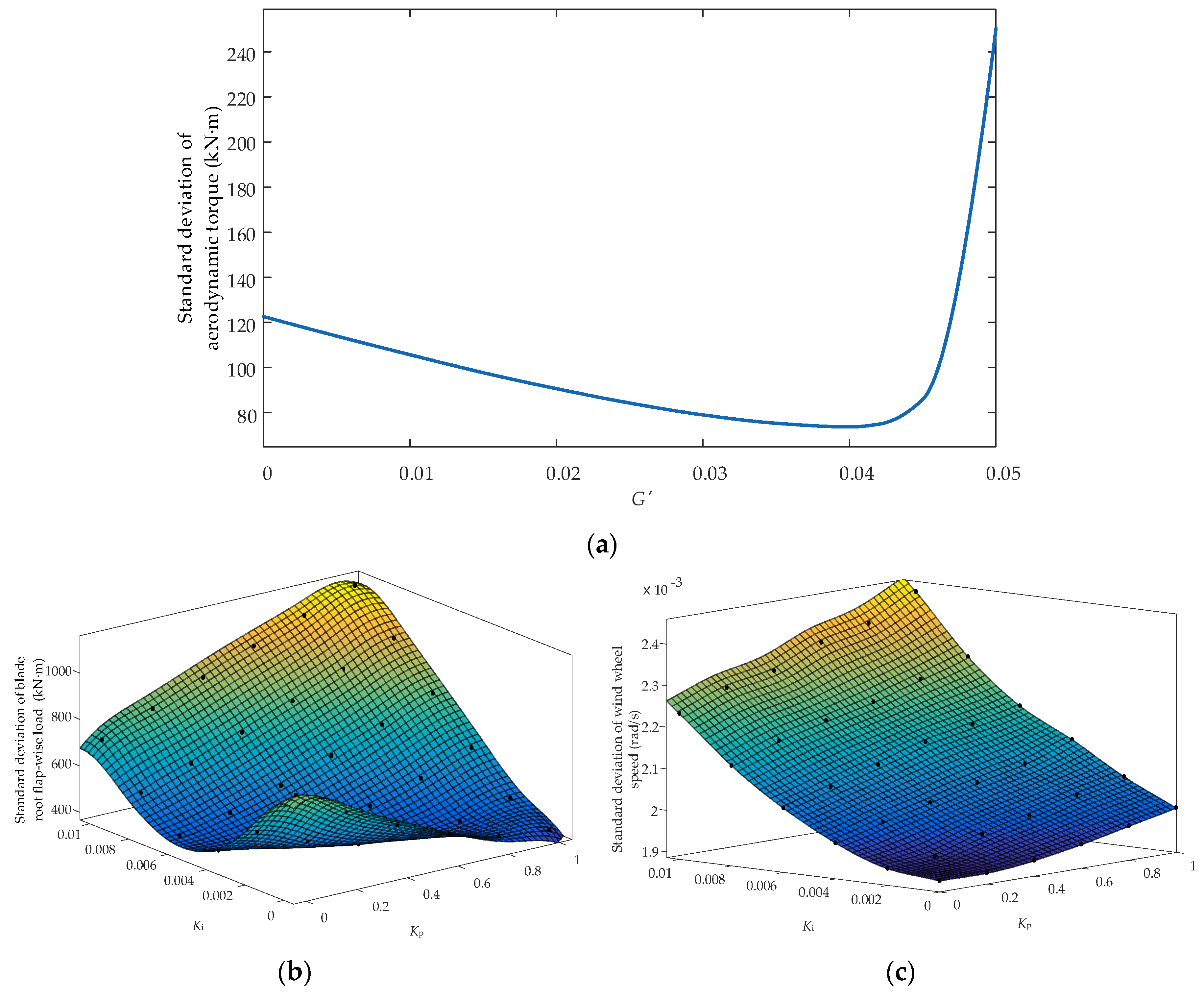
In order to select the appropriate control parameters, the numerical statistical curves with different control parameters are drawn, as shown in
Figure 10. In the simulation, the wind speed at the hub center is constant at 14 m/s, the regular wave height is 2.4 m, the wave period is 6 s, and the wind and wave are in a consistent direction. To select the appropriate control parameters, the standard deviations of aerodynamic torque, blade root flap-wise load and wind wheel speed are tracked since the standard deviation of dynamic responses is a better representation for the fluctuation level of vibration.
Figure 10a shows that the standard deviation of aerodynamic torque decreases first and then increases with the increase of
. According to Equation (18), when
, the additional torque will add a new fluctuation component after offsetting the fluctuating component of hydrodynamic frequency in aerodynamic torque. So, when
, the standard deviation of aerodynamic torque increases with the increase of
.
From
Figure 10b,c, it can be seen that the standard deviation of wind wheel speed increases with the increase of
Kp and
Ki, and within a certain range, the standard deviation of the blade root flap-wise load decreases with the increase of
Kp and
Ki, but when
Kp and
Ki are large at the same time, the vibration of the blade root will be aggravated. Considering the stability of the wind wheel speed, that is, the stability of output active power, and further considering the stability of the blade root flap-wise load, the
Kp value in this paper should be less than 0.6, and the
Ki value should be less than 0.004.
For comparison, here we use turbulent wind and random waves instead of constant wind speed and regular waves. Suppose the turbulent wind intensity is 0.08, the average wind speed at the hub is 14 m/s, the significant wave height of the random wave is 2.5 m, the spectrum peak period is 9.5 s, and the wind and waves are in a consistent direction. The response of aerodynamic torque, blade root load and wind wheel speed of the wind turbine with different pitch control parameters after changing working conditions is shown in
Figure 11.
From
Figure 11, it can be seen that the response of aerodynamic torque, blade root load and wind wheel speed of the wind turbine with different pitch control parameters under random wind-wave conditions is similar to that under regular wind-wave conditions. The suitable ranges of
Kp and
Ki remain unchanged, but the suitable range of
is reduced.
Considering that the control strategy can achieve the effect of vibration reduction without causing too much negative impact on the system, and considering the coupling relationship between the vibration of the wind turbine, the parameters of the controller are selected as follows: , , .
5.3. Simulation and Verification of the Pitch Angle Control Strategy
For comparison, simulations with the collective pitch control (CPC), the individual pitch control strategy based on combined azimuth and load feedback (CALF-IPC) [
7] and the improved individual pitch control strategy (IIPC) proposed in this paper, are implemented both in the time domain and frequency spectrum respectively. In this case, the constant wind and regular wave conditions are the same as that in
Section 5.2, wind shear and tower shadow are considered. The simulation results are shown in
Figure 12,
Figure 13 and
Figure 14.
From
Figure 12, it can be observed that both the proposed IIPC and the CALF-IPC contribute to reducing the fluctuation amplitude of blade root flap-wise load by periodically adjusting the pitch angle of three blades. Moreover, the proposed IIPC can better reduce the fluctuation of the blade root flap-wise load. It can be seen from
Figure 12b that the 1P fluctuation component in blade root flap-wise load under the proposed IIPC is reduced by about 77% and 33%, respectively, compared with that under the CPC and the CALF-IPC.
Meanwhile, shown in
Figure 13, the proposed IIPC has better effectiveness to suppresses the fluctuation of aerodynamic torque than CALF-IPC. As can be seen from
Figure 13b, the frequency spectral density of the aerodynamic torque at the hydrodynamic frequency (0.167 Hz) and at the 3P is noticeably reduced. The results show that the hydrodynamic frequency fluctuation component and the 3P fluctuation component in the aerodynamic torque are effectively suppressed. Furthermore, decreased fluctuation components in the output power with a frequency of 0.167 Hz are also observed in
Figure 13c. This is because of the direct correlation between aerodynamic torque and output power. Therefore, the proposed IIPC reduces the fluctuation of aerodynamic load and improves the stability of output power.
However, from
Figure 14, under the proposed IIPC, the fluctuation of the pitch angle is increased, especially at the hydrodynamic frequency, 1P and 3P frequency, with the fluctuation of the blade root flap-wise load and aerodynamic torque reduced. This might be disadvantageous for pitch actuators, as it can slightly exacerbate fatigue damage to pitch actuators.
In summary, simulation results demonstrate the effectiveness of the proposed IIPC in the smoothing fluctuation of the wind turbine blade root flap-wise load and aerodynamic torque caused by wave impact, wind shear and tower shadow, which is accomplished by aggravating the fatigue damage of the pitch mechanism via frequent pitch angle adjustment. In general, the proposed IIPC can suppress the vibration of the wind turbine, and it has a certain economy.
In addition, considering wind shear and tower shadow, the effectiveness of the control strategy under turbulent wind and random wave conditions is studied, and the turbulent wind and random wave conditions are the same as that in
Section 5.2. The simulation results are shown in
Figure 15.
The simulation results show that by modifying the pitch angle, the proposed IIPC can restrain the 1P pulsation of blade root flap-wise load and weaken the hydrodynamic frequency pulsation (0~0.4 Hz) and 3P pulsation of aerodynamic torque and output power, which verifies the effectiveness of the proposed IIPC under turbulent wind and random wave conditions.


