Article

Energy-Efficiency Improvement and Processing Performance Optimization of Forging Hydraulic Presses Based on an Energy-Saving Buffer System

State Key Laboratory of Materials Processing and Die & Mould Technology, School of Materials Science and Engineering, Huazhong University of Science and Technology, Wuhan 430074, China
*
Author to whom correspondence should be addressed.
Appl. Sci. 2020, 10(17), 6020; https://doi.org/10.3390/app10176020
Submission received: 14 July 2020 / Revised: 14 August 2020 / Accepted: 29 August 2020 / Published: 31 August 2020
(This article belongs to the Special Issue Modelling and Control of Mechatronic and Robotic Systems)

Abstract

:
This paper proposes an energy-saving system based on a prefill system and a buffer system to improve the energy efficiency and the processing performance of hydraulic presses. Saving energy by integrating such systems into the cooling system of a hydraulic press has not been previously reported. A prefill system, powered by the power unit of the cooling system, is used to supply power simultaneously with the traditional power unit during the pressurization stage, thus reducing the usage of pumps and installed power of the hydraulic press. In contrast to the traditional prefill system, the proposed energy-saving system is controlled by a servo valve to adjust flow according to the load profile. In addition, a buffer system is employed to the cooling system to absorb the hydraulic shock generated at the unloading stage, store those shares of hydraulic energy as a recovery accumulator, and then release this energy to power the prefill system and the hydraulic actuator in the subsequent productive process. Finally, through a series of comparative experiments, it was preliminarily validated that the proposed system could reduce the installed power and pressure shock by up to 22.85% and 41%, respectively, increase energy efficiency by up to 26.71%, and provide the same processing characteristics and properties as the traditional hydraulic press.

1. Introduction

Hydraulic presses are commonly used for forging, molding, blanking, punching, deep drawing, and other metal forming operations because of their high load capacity, high power-to-mass ratio, and large force/torque output capacity. However, they are also known for their high energy consumption, low energy efficiency, and poor processing characteristics. As a result of the significant difference between the installed power and the demanded power, 70% of the total energy consumption is attributed to power dissipation and actuation of the hydraulic system. Therefore, improving the energy efficiency of hydraulic presses is an urgent issue that manufacturing industries must resolve [1,2,3,4,5].
Energy dissipation generates from each part of the hydraulic press system when motion or power are transmitted, as shown in Figure 1. It is estimated that only 9.32% of the input energy is transmitted into the forming energy. To better study the energy-saving methods for hydraulic presses, it is necessary to be clear on the energy consumption characteristics of hydraulic system. For this purpose, Zhao [6] established the basic energy flow model of the hydraulic press system, revealed the energy dissipation mechanism of each component, and indicated that the imbalance between installed power and demanded power is the main cause of low energy efficiency. Installed power is designed to meet the maximum power requirements of PS. However, as the same power unit also serves other low-power operations, mismatch between installed power and demanded power occurs.
During the past decades, researchers are applying an increasing amount of effort to achieve the match between the installed power and the required power for hydraulic presses. As reported by Zhao [6] and Huang [7], energy-matching methods for hydraulic presses can be divided into two categories: energy-matching methods and energy-recovery methods.
A common approach based on an energy-matching mechanism is the volume control electrohydraulic system driven directly by various kinds of variable-speed motors and variable-displacement pumps. The control of pressure, flow, and direction of working liquid is achieved by changing the rotation speed or output displacement. Quan and Helduser [8] applied variable-speed motors and constant-displacement pumps in hydraulic drive units to match load variations. Su et al. [9] applied variable-frequency motors in the hydraulic press to reduce the mismatch between output power and load power. Camoirano and Dellepiane [10] employed variable-frequency drive (VFD) technology to achieve more efficient energy management as well as the precise control of torque and speed of AC motors. Wang et al. [11] adopted a calibration model with a genetic algorithm to adjust the variable-speed pump flow rate to their designated value and achieve an energy-saving ratio of at least 16.1%. Ge [12] adopted a variable-speed motor to drive a variable-displacement pump and employed a matching method based on segmented speed and continuous displacement control of the pump to reduce the throttle loss. The energy-saving ratio under partial load condition can be up to 33%. Since there is limited scope for further increasing the electrohydraulic unit’s efficiency, researchers have also focused on the design of hydraulic control circuits to reduce the mismatch. Load sensing systems [13], hydraulic adaptive systems [14], fuzzy control systems [15], close-loop volume control systems [16], negative flow control systems [17], and secondary regulation systems are all useful methods to match the load by regulating operating parameters and system states. As these methods achieve matching by adjusting the output flow, speed, and pressure, the installed power remains unaltered.
Many papers on energy-recovery methods have been published in recent years. A lot of energy-recovery circuits have been applied in hydraulic press machines. Yan et al. [18] proposed a flywheel energy-saving system (FESS) that can store the redundant energy at no-load stages and low-load stages and then release the stored energy at high-load stages. Dai et al. [19] applied a hydraulic accumulator to a 20 MN fast forging hydraulic press to realize energy conversion by absorbing large flow–pressure pulses and hydraulic shock. The results show that the hydraulic accumulator has promising energy-saving effects. Triet and Ahn [20] utilized a hydraulic accumulator and a flywheel to realize energy recovery and presented a control strategy for this energy-saving method. Ven [21] developed a novel hydraulic accumulator that can keep the hydraulic system pressure constant by using a piston with an area that varies with stroke. Compared with conventional recovery accumulators, this new accumulator could significantly increase the energy storage density. Xia et al. [22] proposed an integrated drive and energy recuperation system for a hydraulic excavator, and the large gravitational potential energy of the boom was recovered by a three-chamber hydraulic cylinder. Lin et al. [23] combined the advantages of hydraulic accumulators and electric accumulators and presented a compound energy recovery system to improve the energy efficiency of hydraulic equipment. Through a series of experiments, they validated that the compound system could increase the energy efficiency by approximately 39%. Fu et al. [24] studied the energy-saving potential of the boom cylinder with an accumulator in the hybrid excavator system. The results of simulations and experiments showed that the closed hydraulic regeneration system had a high recovery efficiency. Examples of applying energy recovery systems also include generator–super capacitor energy recovery and the gas cylinder energy recovery system [25]. 
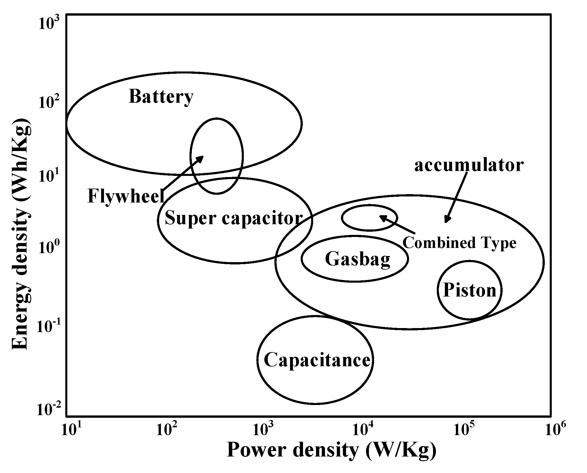
Figure 2 gives the energy density of different energy recovery circuits. However, Huang [26] pointed out that the low utilization efficiency of the recovery energy is also an important problem that cannot be ignored. In general terms, an energy recovery process is composed of two sub-processes: the recovery process and the reutilization process. The number of energy conversions increases with the integration of an energy recovery system, thereby increasing the system’s structural complexity and causing low energy efficiency as well.
In summary, energy efficiency and mismatch between the demanded power and the installed power can be significantly improved by using the aforementioned methods. However, most of those methods only consider energy efficiency and ignore the impact that they have on the hydraulic press itself. Therefore, most of the energy-saving presses present complicated structures and poor practicality. Furthermore, most of the existing studies in the literature only focus on the hydraulic power units and hydraulic control system; they ignore that the hydraulic press is a forming machine composed of various functional systems, such as the hydraulic actuating system, hydraulic cooling system, and other auxiliary systems. Each of these systems waste a large amount of energy during the forming process and has great potential to save energy.
Therefore, in contrast to existing energy-saving methods, the system in this paper focuses on the hydraulic cooling system as a novel starting point and proposes an energy-saving buffer system to improve the energy efficiency of a single press. A reduction of the installed power and improvement in energy efficiency can be achieved by integrating the prefill system into the hydraulic cooling system, whereas noise pollution, processing properties, and structural complexity can be improved by adding a buffer system. In addition, a servo valve is employed to adjust the supplied flow rate of the energy-saving buffer system according to the load profiles. Finally, the proposed energy-saving system was applied to a 13MN forging hydraulic press as a case study, and the results shows its significant economic and energy-saving potential.

2. Energy-Saving Method of the Hydraulic Press

2.1. Energy Characteristics of the Hydraulic Press

In 
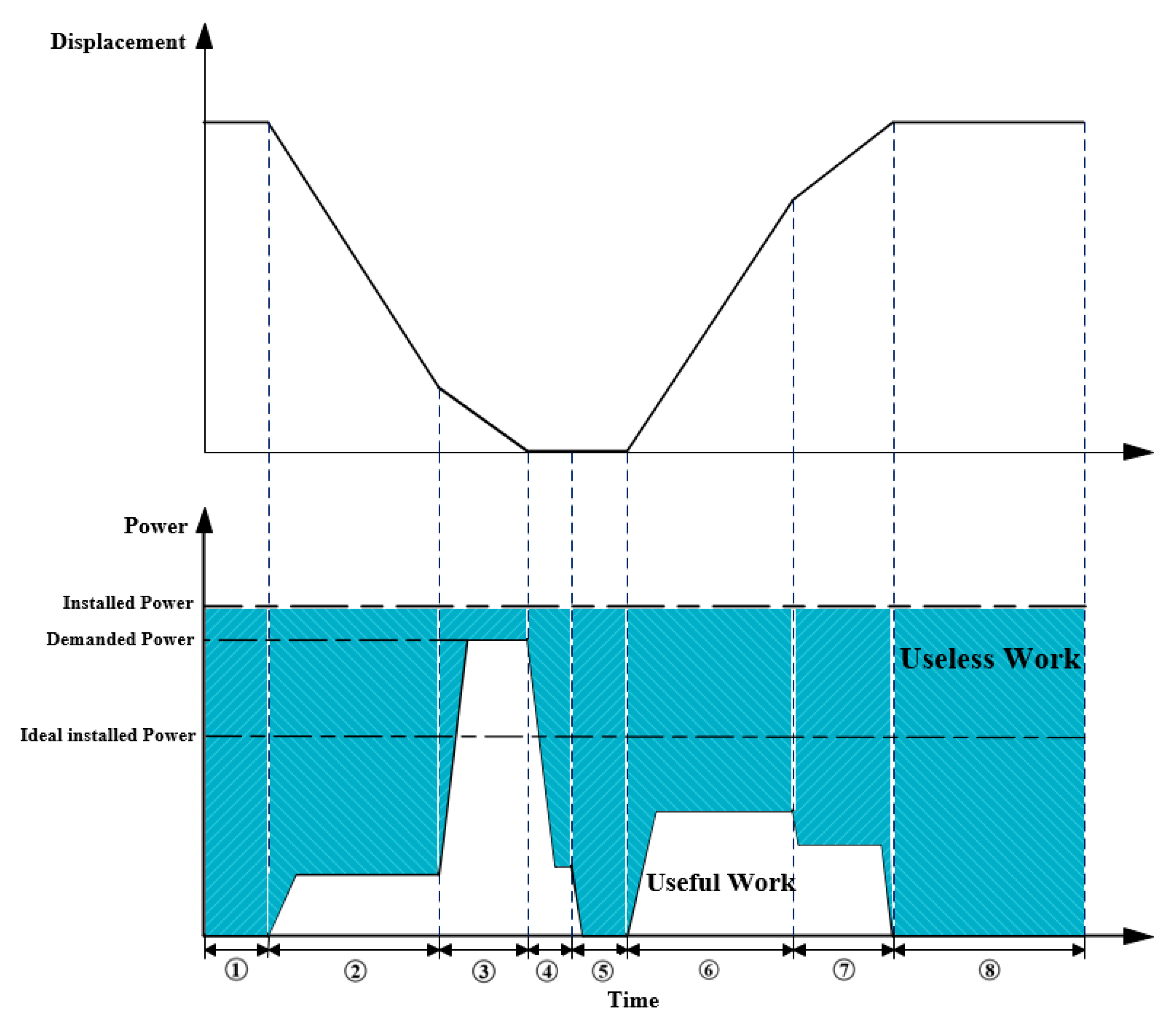
Figure 3, a diagram showing the working cycle of a hydraulic press is presented. The operations performed by the hydraulic press include waiting within a working cycle (Stages 1 and 8, WT), fast falling (Stage 2, FF), pressing with slow falling (Stage 3, PS), pressure maintaining (Stage 4, PM), unloading (Stage 5, UL), fast returning (Stage 6, FR), and slow returning (Stage 7, SR). All these stages are also part of the forming process.
In traditional methods, installed power is designed to meet the maximum power requirements of Stage 3, which is much larger than the operating power of the other working stages. However, the duration of Stage 3 is only of a very small percentage of the total operating time, leading to high energy consumption and low energy efficiency. Furthermore, hydraulic presses operate performing periodic movements; the intermittent time between two adjacent cycles is almost equal to the duration of a cycle. Once hydraulic presses start running, they would not stop unless the hydraulic system reaches the unloaded state and the demanded power is zero; this leads to a large amount of power lost inadvertently. As shown in Figure 1, the white and blue areas represent useful work and useless work, respectively. Useless work is converted into heat or another useless form of energy during the operation of hydraulic presses; this is harmful to the processing properties.
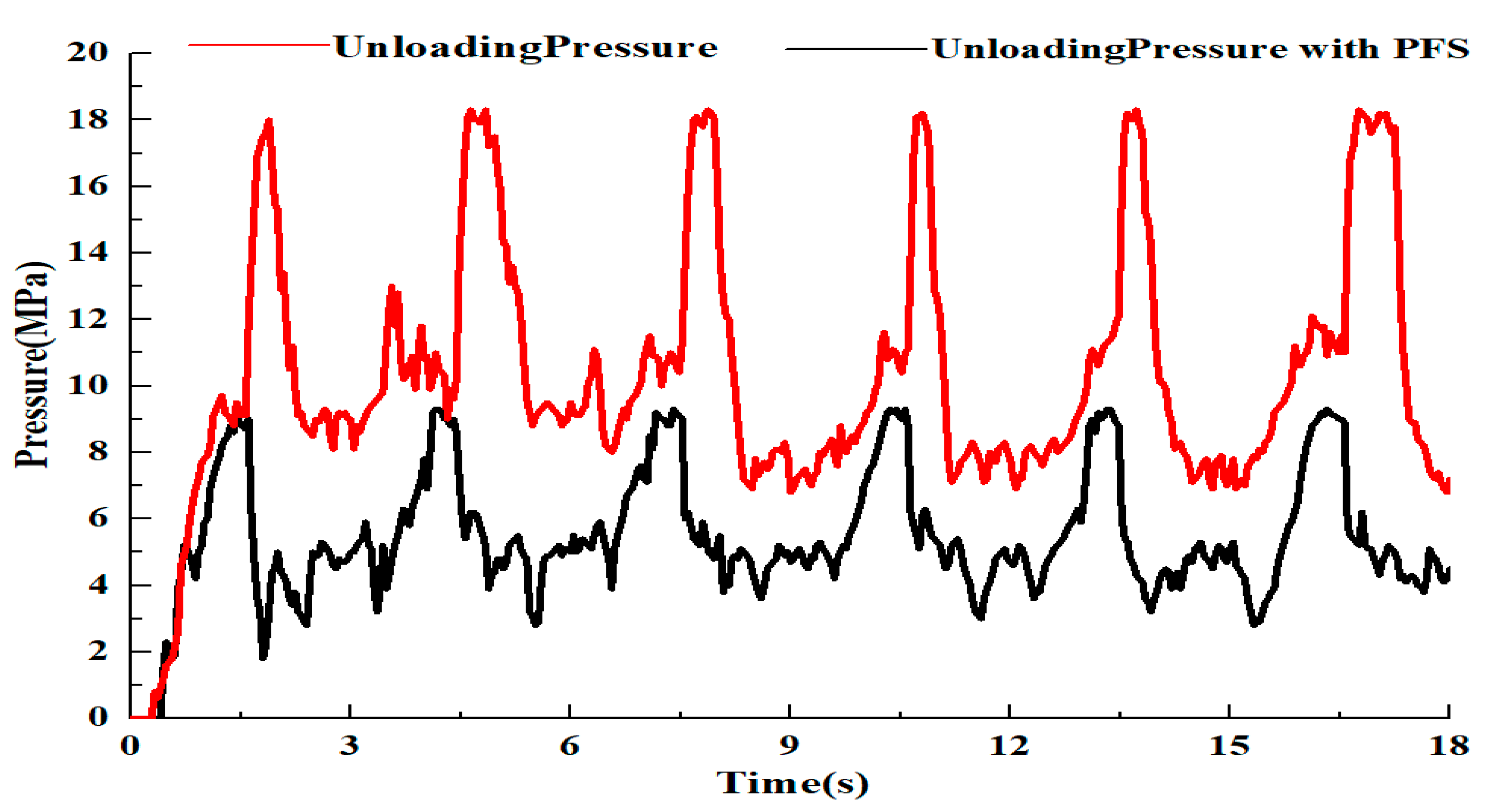
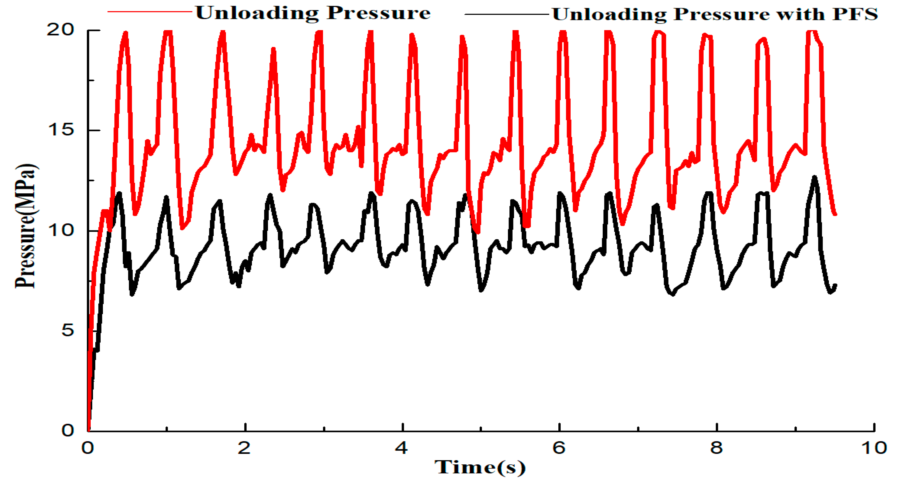
When the hydraulic press is unloading, a large flow is unloaded during the processing cycle, leading to a considerable amount of energy being wasted by the traditional power unit. In addition, when the hydraulic cylinder rises rapidly with high working pressure, the high-pressure oil cannot be completely unloaded. In consequence, the residual high-pressure oil enters the hydraulic pipeline causing high vibration and huge noise pollution. The phenomena presented above constitute the main reasons for the low energy efficiency and poor processing performance in hydraulic presses. Theoretically, if an external power system could supply energy to the hydraulic press simultaneously with the main power system during Stage 3, the installed power would be reduced and the energy efficiency would be increased.

2.2. Methodology

By analyzing in detail the reasons for the high installed power of hydraulic presses, this paper envisages the addition of an instantaneous power source during the PS stage (Stage 3). The power source can energize the hydraulic press simultaneously with the traditional power unit so as to reduce the power burden of the traditional power unit and thereby reduce the installed power of the hydraulic press. Based on this idea, an energy-saving method featuring a prefill system and a buffer system is proposed.
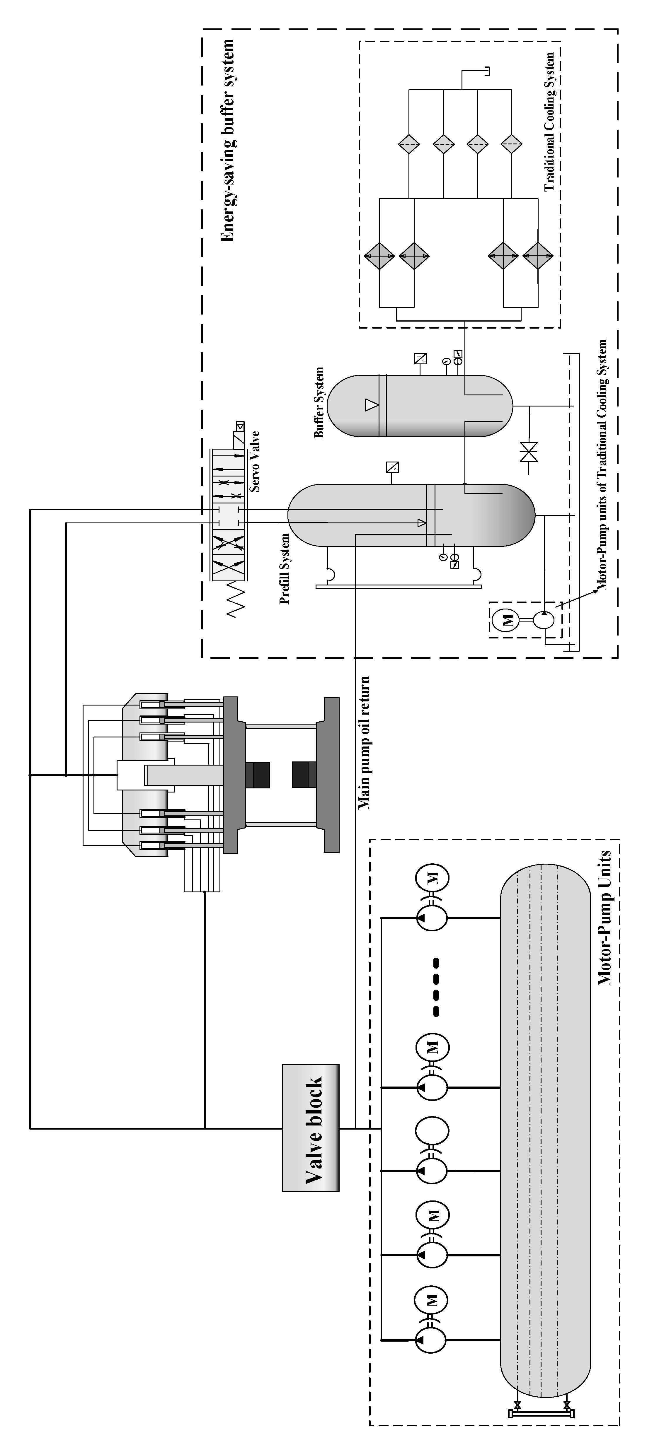
The proposed energy-saving system is developed by integrating a prefill system and a buffer system into the cooling system of the traditional hydraulic press, as shown in Figure 4. The pivot of the proposed system is the prefill system, which could supply high-pressure oil to the main cylinder similar to a motor-pump unit. In order to ensure the efficiency of the supplemental power and reduce pipeline losses, the prefill system is installed next to the hydraulic cylinder instead of tens of meters away from the hydraulic press, as in the traditional power unit. In addition, a servo valve is employed to adjust the output flow according to the load profiles, thereby achieving high-precision energy supplement. Based on this method, the installed power can be set at the ideal installed power as shown in Figure 1. During Stages 1, 2, 4, 5, 6, 7, and 8, the traditional power unit based on the ideal installed power can energize the press by itself, the prefill system is not used, and the servo valve outside the liquid-filling tank closes to reduce energy loss. When the hydraulic press operates at Stage 3, the power (or oil flow) required by the hydraulic press increases and exceeds the maximum value, it is difficult for the traditional hydraulic power unit alone to complete the pressurization process. At this time, the servo valve outside the liquid-filling tank opens with high accuracy, and the prefill system starts to supply power to the hydraulic press together with the traditional power unit. In this manner, power reliance on the traditional power unit is significantly reduced.
Furthermore, as depending on the power unit of the traditional cooling system, the addition of the prefill system does not require an increase in the number of motors and pumps to meet the flow and power requirements of Stage 3. Therefore, the usage of motor-pump units in the whole hydraulic system can be significantly reduced; the energy dissipation caused by the high installed power can be remarkably reduced in the low-load and no-load stage. Moreover, by reducing the number of pumps, the equipment footprint can be reduced, the structure of the equipment as a whole can be more compact, and the equipment utilization rate can be significantly improved.
When the hydraulic press operates at Stages 4 and 5, since the hydraulic press moves extremely quickly during the unloading stage, high-pressure oil cannot be completely unloaded. In consequence, the oil returning from the returning cylinder has high pressure and thus has a great impact on the prefill system and causes massive large noise pollution. To ensure the power supply of the prefill system successively improves the processing performance of the hydraulic press, the advantages of hydraulic accumulators are adopted in the method described in this paper by integrating a buffer system as an auxiliary facility. The buffer system, installed after the prefill system, can temporarily store the returning oil, absorb the high pressure in the oil to reduce the pressure shock in the system, and thus improve the processing performance of the hydraulic press. Furthermore, the high-pressure oil temporarily stored in the buffer system can also energize the hydraulic press together with the prefill system during Stage 3, allowing the energy-saving system to have a higher kinetic energy output and thus attain higher energy efficiency.

3. Energy Consumption Model and Theoretical Analysis

A hydraulic press is a closed energy conversion system composed of electric energy, mechanical energy, hydraulic energy, and forming energy, and the total energy consumption of a single hydraulic press is in the form of electrical energy.
The required electrical energy of a hydraulic press is determined by the flow rate q and the working pressure p of the actuator, which changes with the operation stage. Taking into account the energy conversion efficiency of the hydraulic system, the electrical energy demanded ( E e l e c t r i c 1 ) by the hydraulic machine to complete forming actions can be expressed as Equation (1):
E e l e c t r i c 1 = i T 0 T 0 + T 1 p · q 1 η D r i v e d t
where stage i includes the PS stage and the FF stage; η D r i v e is the energy efficiency of motor-pump units; T 0 is the start time of stage i; and T 1 is the duration of stage i.
In terms of a hydraulic press with an energy-saving buffering system, Equation (1) can be divided into two parts,
E e l e c t r i c 1 = E 1 + E 2     = i ( T 0 T 0 + T 1 p T M P · q T M P 1 η D r i v e d t     + T 0 T 0 + T 1 p P F S · q P F S d t )
where E 1 and E 2 are the energy provided by the traditional motor pumps and the prefill system, respectively; p T M P and q T M P are the pressure and flow rate provided by the traditional motor pumps, respectively; and p P F S and q P F S are the pressure and flow rate provided by the prefill system, respectively.
Apart from the electrical energy demanded by the hydraulic main circuit during the FF and PS stages, other electrical energy ( E e l e c t r i c 2 ) demanded by the overflow circuit and the unloading circuit during the PM, PR, and WT stages can be expressed as Equation (3):
E e l e c t r i c 2 = e ( T m P 1 d t + T n P 2 d t + T i P 3 d t )
where P 1 , P 2 , and P 3 are the motor power of the UL stage, the FR stage, and the WT stage, respectively; and T m , T n , and T i are the duration of the UL, FR, and WT stages.
Therefore, total energy consumption in a working cycle ( E e l e c t r i c T o t a l ) can be obtained:
E e l e c t r i c T o t a l = E 1 + E e l e c t r i c 2 .
Since the hydraulic actuator does not output mechanical energy until the forming process completes, the forming energy ( E F o r m i n g ) of one working cycle can be expressed as:
E F o r m i n g = i i F N P · h ˙ d t
where h is the height of the piston rod; and F N P is the forming pressure of the hydraulic press.
Therefore, the energy efficiency ( η E F , electrical-forming energy) of the proposed hydraulic press can be expressed as Equation (6):
η E F = E F o r m i n g E e l e c t r i c T o t a l .
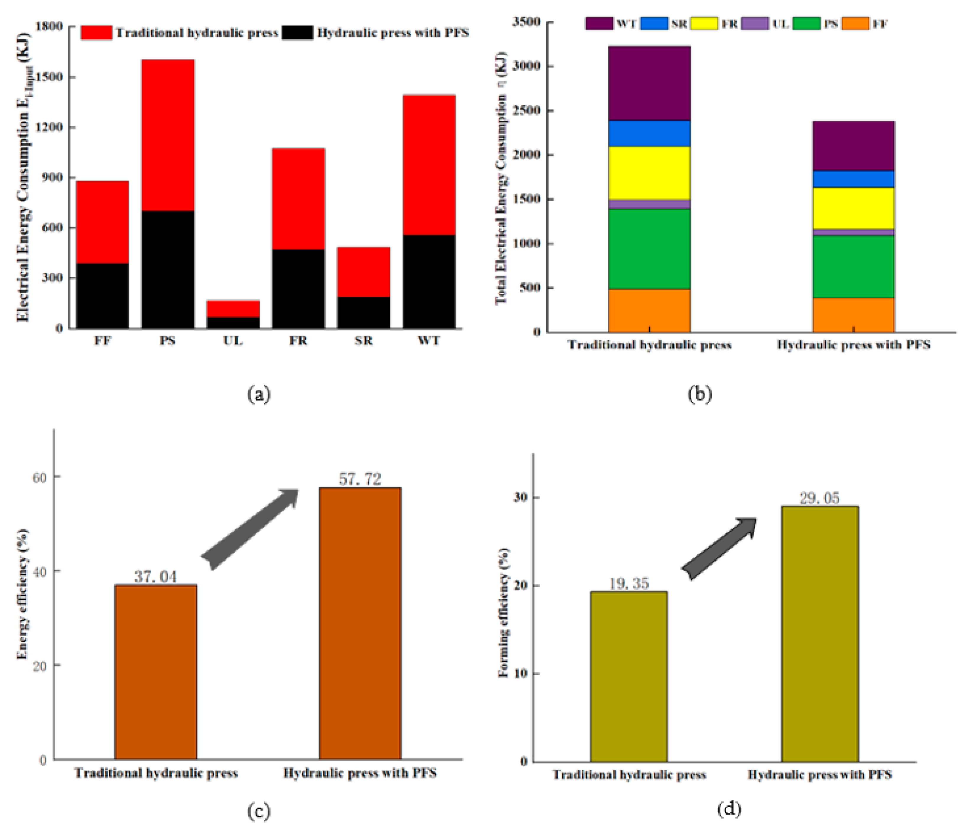
As shown in the above analysis, the integration of the prefill system and the buffer system can significantly reduce the power burden of traditional motor pumps during the high-load stage, and a reduction of installed power can be realized. In addition, both overflow losses during the PM stage and throttling losses during the idle state of the press could be greatly reduced because of the reduction of installed power, thereby improving the energy efficiency of the hydraulic press. Detailed energy-efficiency improvement is discussed in the following section.

4. Case Study

4.1. Experimental Scheme

To assess the energy-saving efficiency and processing performance of the proposed system, the system was tested on a 13 MN hydraulic press machine. The experimental setup (see Figure 5) consisted of a liquid-providing tank (volume and flow rate of 23 m3 and 5800 L/min, respectively, Huawei, Yancheng, China), a buffering tank (volume of 6 m3, Huawei, Yancheng, China), a hydraulic power unit containing an asynchronous motor (Y315S-4; rated power and speed of 110 kW and 1480 rpm, respectively, YKP, Botou, China), an oil pump (A2F250R2P2; rated speed and flow rate of 1480 rpm and 360 L/min, respectively, Rexroth, Shanghai, China), coolers, and filters. In addition, a DT-8850 noise meter is employed to measure the noise generated during the machining process, and body vibration is measured by the technical operator at the processing site.
To test the operating stability of the system and the dynamic responsiveness during the rehydration process, two common forging methods, fast forging and constant forging, were selected and performed both on the proposed hydraulic press and a traditional hydraulic press. The forging frequency of constant forging and fast forging was set at 20 times per minute and 90 times per minute, respectively. The maximum forming pressure was 35 MPa. The installed power of the proposed forging press was set at 810 kW, while the traditional hydraulic press was 1050 kW.
Table 1 details the experimental parameters of this experiment. The pressure and flow rate of the prefill system (PFS) and the traditional power units (TPU) were recorded by a pressure gauge and a flow sensor and then uploaded to a computer.

4.2. Processing Performance Analysis

The forging frequency was set to 90 times per minute and 20 times per minute, respectively. The nominal pressure was set to 35 MPa. The relationships between TPU pressure and prefill pressure are shown in Figure 6 and Figure 7.
As it can be seen in Figure 6 and Figure 7, the hydraulic press ran smoothly (without vibration) in the no-load and low-load stages. The TPU was used to supply energy to maintain the normal operation of the press, while the servo valve outside the liquid-providing tank was closed so that the output pressure and flow of the liquid-filling system was approximately zero. When the hammer of the hydraulic press contacted the forging workpiece, the load power rose and exceeded the nominal power supplied by the TPU; the servo valve outside the PFS opened with high accuracy, and the output power and flow of the PFS were used in conjunction with those of the TPU as the load pressure was reaching its maximum pressure. In the fast forging process, the servo valve remained open in order to ensure timely rehydration, since the timespan of one fast forging cycle was extremely short (see Figure 6).
When the press operated at the unloading stage, the traditional hydraulic system generated an impact pressure of up to 20 MPa in 0.04 s, causing a great impact on hydraulic pipes and beams. Many oil pipe ruptures and beam bending deformations are caused by this phenomenon, seriously affecting machining accuracy and the service life of the hydraulic press. Figure 8 and Figure 9 show that the pressure-relief impact was well improved by integrating a buffer system. Since the PFS and the buffer system were installed close to the hydraulic cylinder, the high-pressure oil generated at the unloading stage directly entered the liquid-filling tank and the buffer tank without traveling a long distance along the hydraulic pipelines. Therefore, hydraulic impact and oil leakage could be reduced to a large extent, so as to improve the hydraulic working environment and reduce environmental pollution. According to experimental statistics, regardless of the forging method, adding the proposed system to a hydraulic press can reduce hydraulic impact by at least 9.2 MPa.
Through several test experiments, the experimental data from Figure 6, Figure 7, Figure 8 and Figure 9 are summarized in Table 2 and Table 3, in which Table 2 and Table 3 are the results of the experiments at the PS and unloading stage for different forging methods, respectively.
When the forging hydraulic press operates at the low-load or no-load stage, the energy supplied by the TPU is sufficient for the hydraulic press to operate normally, and the PFS does not work. As seen from Figure 6 and Figure 7 and Table 3, when the hydraulic press operates at Stage 3, the load power rises and exceeds the maximum power the TPU could output, the servo valve outside the PFS opens, and then the PFS outputs high-pressure oil and energizes the main working cylinder together with the TPU; the maximum output pressure and flow rate of the TPU are 28.1 MPa and 2900 L/min, respectively, while the load pressure and flow rate of the press are 35 MPa and 4400 L/min. The difference between the load pressure and the output pressure of the TPU is the energy provided by the PFS, which are 5.4 MPa and 1480 L/min, respectively. The average pressure-saving rate for the two forging methods is 19.3% and 17.5%, respectively. Combined with the flow rate and the formula P = p q , the maximum power saving rate of 20.1% could be obtained through calculations.
From Table 3, when the forging frequency was set at 90 times per minute (fast forging), the pipeline pressure dropped to 9.7 MPa, while the pressure shock and noise pollution decreased by 52.2% and 28.6%, respectively, compared with the traditional hydraulic press. When the forging frequency was set at 20 times per minute (constant forging), the pipeline pressure dropped to 9.2 MPa, the pressure shock and noise pollution decreased by 49.7% and 28%, respectively. In addition, although the cooling system was retrofitted, the system temperature remained within a low range, which was generally lower than that of the traditional hydraulic press.

4.3. Energy Consumption Analysis of the Two Presses

During the forging process, each motor pump in the drive unit changes the state of its access to the hydraulic system according to the energy demand of different operations, and one drive unit, which is useless in an operation, is set at an unloading state by switching the pressure-relief valve. Table 4 shows the compositions of the drive system of the two hydraulic presses and the number of motor pumps connected for each processing stage.
In this study, the energy consumption of a hydraulic press was scaled by measuring the active electricity consumption of motor pumps. A power meter and an data acquisition card were selected to measure and receive the voltage and current through the motors at any time, respectively. Then, the real-time measured data were transmitted to the PC after processing.
During the forming process, the energy efficiency of a hydraulic press can be expressed as follows,
η = E F o r m i n g i E i I n p u t · 100 %
where i is all the forming operations, including FF, PS, UL, FR, SR, and WT. E i I n p u t is the energy consumed by the hydraulic machine to complete the i-th operation, which can be obtained by Equation (8).
E i I n p u t = t i S t a r t t i E n d P i ( t ) d t = t i S t a r t t i S t a r t P i · Δ t
where P i is the active power of each operation, which can be obtained by the power meter, and t i S t a r t and t i S t a r t are the start time and the end time of the i-th operation, respectively.
According to Equation (8), the active electrical energy consumption of motors was obtained by experiments. The electricity consumption, useful energy, and energy efficiency of the two presses from experimental testing are shown in Table 5 and Table 6.
The traditional hydraulic press is equipped with 9 sets of motor pumps, of which the installed power is up to 1050 kW. According to Table 6, the total electric energy consumed to complete a working cycle is 3227.66 KJ, and only 31.01% of the input energy is converted into useful energy. Besides this, as a result of the pipe-valve energy loss, overflow energy loss, and other energy losses, only 17.35% of the input energy is used to form the workpiece. However, by integrating PFS into the press, the energy consumption of each stage significantly improved. The experimental data from Table 5 and Table 6 compared with the traditional hydraulic press are summarized in Figure 10.
As shown above, since the installed power of the hydraulic press equipped with PFS was lower than that of the traditional press by 22.86%, the throttling loss and the no-load loss of the press were significantly reduced, and the average electrical energy consumption was minimized in each stage, as shown in Figure 10a. Total electrical energy consumption was reduced from 3227.66 KJ to 2382.76 KJ, so 804.90 KJ energy was saved per working cycle. During the PS stage, as the hammer contacted the forming workpiece, the load power rose and exceeded the nominal power supplied by the TPU, the servo valve outside the PFS opened, and the output power and flow of the PFS were used in conjunction with those of the TPU as the load pressure was reaching its maximum pressure. The difference between the input energy of the two presses is the energy provided by the PFS, which is about 198.61 KJ. After several experimental tests, compared with the traditional hydraulic press, the overall energy efficiency and the forming efficiency of the hydraulic press with PFS were improved by 26.71% and 11.70%, respectively.

5. Conclusions

Given the low energy efficiency and poor processing performance of the hydraulic press, this paper proposes a method featuring an energy-saving buffer system to reduce the installed power and improve processing performance. In this method, a liquid-filling system is used to supply power and an oil flow rate that the TPU cannot provide at the high-load stage. As it is not necessary to increase the number of motor pumps to meet the flow requirements, the motor-pump usage of the whole system is significantly reduced. In consequence, the installed power of the hydraulic press is reduced, and cost reduction and energy savings are achieved. Furthermore, to mitigate the high-pressure impact and noise pollution at the unloading stage, a buffer system is integrated into the system to absorb the high-pressure returning oil. In consequence, the pressure shock problem is addressed, and the service lifespan of the hydraulic press is increased. The proposed system was tested in a 13 MN hydraulic press in which an industrial press was used. Through a series of comparative experiments, it was preliminarily validated that the proposed system can reduce pump usage and pressure shock by up to 30% and 41%, respectively, increase energy efficiency by up to 26.71%, reduce noise pollution and installed power by 28% and 22.85%, respectively, and provide the same processing characteristics and properties as the traditional hydraulic press.
To better improve the energy efficiency of the hydraulic press, our future work will concentrate on the control strategies of the PFS to achieve higher precision output. Other research directions include the optimal design of the PFS and the buffering system for a given hydraulic press.

Author Contributions

Conceptualization, X.Y.; Methodology, X.Y. and B.C.; validation, X.Y. and B.C.; formal analysis, X.Y. and B.C.; data curation, X.Y.; writing original draft preparation, X.Y.; Funding, B.C.; writing-review and editing, B.C. All authors have read and agreed to the published version of the manuscript.

Funding

This work is financed by Huazhong University of Science and Technology and Jiangsu Huawei Machinery Manufacturing Co. Ltd.

Acknowledgments

The work is supported by Huazhong University of Science and Technology and Jiangsu Huawei Machinery Manufacturing Co. Ltd.

Conflicts of Interest

The authors declare no conflict of interest.

Abbreviations

TPUtraditional power units
PFSprefill system
FFfast falling
PSpressure with slow speed
PMpressure maintaining
ULunloading
FRfast returning
SRslow returning
WTwaiting stage

References

  1. Li, L.; Huang, H.H.; Liu, Z.F.; Li, X.Y.; Triebe, M.J.; Zhao, F. An energy-saving method to solve the mismatch between installed and demanded power in hydraulic press. J. Clean. Prod. 2016, 139, 636–645. [Google Scholar] [CrossRef]
  2. Duflou, J.R.; Sutherland, J.W.; Dornfeld, D.; Herrmann, C.; Jeswiet, J.; Kara, S.; Hauschild, M.; Kellens, K. Towards energy and resource efficient manufacturing: A processes and systems approach. CIRP Ann. Manuf. Technol. 2012, 61, 587–609. [Google Scholar] [CrossRef] [Green Version]
  3. Lin, T.; Chen, Q.; Ren, H.; Huang, W.; Chen, Q.; Fu, S. Review of boom potential energy regeneration technology for hydraulic construction machinery. Renew. Sustain. Energy Rev. 2017, 79, 358–371. [Google Scholar] [CrossRef]
  4. Xu, Z.; Liu, Y.; Hua, L.; Zhao, X.; Guo, W. Energy analysis and optimization of main hydraulic system in 10,000 kN fine blanking press with simulation and experimental methods. Energy Convers. Manag. 2019, 181, 143–158. [Google Scholar] [CrossRef]
  5. Mousa, E.; Kazemi, M.; Larsson, M.; Karlsson, G.; Persson, E. Potential for Developing Biocarbon Briquettes for Foundry Industry. Appl. Sci. 2019, 9, 5288. [Google Scholar] [CrossRef] [Green Version]
  6. Zhao, K.; Liu, Z.F.; Yu, S.R.; Li, X.Y.; Huang, H.H.; Li, B.T. Analytical energy dissipation in large and medium-sized hydraulic press. J. Clean. Prod. 2015, 103, 908–915. [Google Scholar] [CrossRef]
  7. Huang, H.H.; Zou, X.; Li, L.; Li, X.Y.; Liu, Z.F. Energy-Saving Design Method for Hydraulic Press Drive System with Multi Motor-Pumps. Int. J. Precis. Eng. Manuf. Green Technol. 2019, 6, 223–234. [Google Scholar] [CrossRef]
  8. Quan, L.; Helduser, S. Energy Saving and High Dynamic Hydraulic Power Unit Based on Speed Variable Motor and Constant Hydraulic Pump. China Mech. Eng. 2003, 14, 606–609. [Google Scholar]
  9. Su, C.L.; Chung, W.L.; Yu, K.T. An Energy-Savings Evaluation Method for Variable-Frequency-Drive Applications on Ship Central Cooling Systems. IEEE Trans. Ind. Appl. 2014, 50, 1286–1294. [Google Scholar] [CrossRef]
  10. Camoirano, R.; Dellepiane, G. Variable frequency drives for MSF desalination plant and associated pumping stations. Desalination 2005, 182, 53–65. [Google Scholar] [CrossRef]
  11. Wang, H.; Wang, H.Y.; Zhu, T. A new hydraulic regulation method on district heating system with distributed variable-speed pumps. Energy Convers. Manag. 2017, 147, 174–189. [Google Scholar] [CrossRef]
  12. Ge, L.; Quan, L.; Zhang, X.G.; Zhao, B.; Yang, J. Efficiency improvement and evaluation of electric hydraulic excavator with speed and displacement variable pump. Energy Convers. Manag. 2017, 150, 62–71. [Google Scholar] [CrossRef]
  13. Lovrec, D.; Kastrevc, M.; Ulaga, S. Electro-hydraulic load sensing with a speed-controlled hydraulic supply system on forming-machines. Int. J. Adv. Manuf. Technol. 2009, 41, 1066–1075. [Google Scholar] [CrossRef]
  14. Feng, L.; Yan, H. Nonlinear Adaptive Robust Control of the Electro-Hydraulic Servo System. Appl. Sci. 2020, 10, 4494. [Google Scholar] [CrossRef]
  15. Chen, B.J.; Huang, S.H.; Jin, L.; Gao, J.F. Control Strategy for Free Forging Hydraulic Press. Chin. J. Mech. Eng. 2008, 44, 304–307. [Google Scholar] [CrossRef]
  16. Ferreira, J.A.; Sun, P.; Grácio, J.J. Close loop control of a hydraulic press for springback analysis. J. Mater. Process. Technol. 2006, 177, 377–381. [Google Scholar] [CrossRef]
  17. Gao, F.; Pan, S.X. Experimental study on model of negative control of hydraulic system. China Mech. Eng. 2005, 41, 49–54. [Google Scholar] [CrossRef]
  18. Yan, X.P.; Chen, B.J.; Zhang, D.W.; Wu, C.X.; Luo, W.X. An energy-saving method to reduce the installed power of hydraulic press machines. J. Clean. Prod. 2019, 233, 538–545. [Google Scholar] [CrossRef]
  19. Dai, M.Q.; Zhao, S.D.; Yuan, X.M. The Application Study of Accumulator Used in Hydraulic System of 20MN Fast Forging Machine. J. Appl. Mech. 2011, 80, 870–874. [Google Scholar] [CrossRef]
  20. Triet, H.H.; Ahn, K.K. Comparison and assessment of a hydraulic energy- saving system for hydrostatic drives. Proc. Inst. Mech. Eng. Part I J. Syst. Control Eng. 2011, 225, 21–34. [Google Scholar] [CrossRef]
  21. Van de Ven, J.D. Constant pressure hydraulic energy storage through a variable area piston hydraulic accumulator. Appl. Energy 2013, 105, 262–270. [Google Scholar] [CrossRef]
  22. Xia, L.P.; Quan, L.; Ge, L.; Hao, Y.X. Energy efficiency analysis of integrated drive and energy recuperation system for hydraulic excavator boom. Energy Convers. Manag. 2018, 156, 680–687. [Google Scholar] [CrossRef]
  23. Lin, T.l.; Huang, W.P.; Ren, H.L.; Fu, S.J.; Liu, Q. New compound energy regeneration system and control strategy for hybrid hydraulic excavators. Autom. Constr. 2016, 68, 11–20. [Google Scholar] [CrossRef]
  24. Fu, S.; Chen, H.; Ren, H.; Lin, T.; Miao, C.; Chen, Q. Potential Energy Recovery System for Electric Heavy Forklift Based on Double Hydraulic Motor-Generators. Appl. Sci. 2020, 10, 3996. [Google Scholar] [CrossRef]
  25. Fan, Y.J.; Mu, A.L.; Ma, T. Design and control of a point absorber wave energy converter with an open loop hydraulic transmission. Energy Convers. Manag. 2016, 121, 13–21. [Google Scholar] [CrossRef]
  26. Huang, N.; Yang, S.; Chen, Y. Development of machine tools and large tonnage hydraulic automatic hydraulic fine blanking press. Mach. Tool Hydraul. 2011, 2011, 4. [Google Scholar]
Figure 1. Energy dissipation of each energy conversion unit during a working cycle. (E-M, electrical–mechanical energy unit; M-H, mechanical–hydraulic energy unit; H-H, hydraulic–hydraulic energy unit; H-M, hydraulic–mechanical energy unit; M-F, mechanical-forming energy unit).
Applsci 10 06020 g001
Figure 2. Power density and energy density of different energy-recovery systems.
Applsci 10 06020 g002
Figure 3. Hydraulic press working cycle diagram and comparison between installed and demanded power.
Applsci 10 06020 g003
Figure 4. Diagram of the proposed energy-saving buffer system.
Applsci 10 06020 g004
Figure 5. Photograph of the energy-saving buffering system.
Applsci 10 06020 g005
Figure 6. Output pressure of the prefill system and the main power unit during fast forging.
Applsci 10 06020 g006
Figure 7. Output pressure of the prefill system and the main power unit during constant forging.
Applsci 10 06020 g007
Figure 8. Unloading pressure of the hydraulic press with the energy-saving system and the traditional hydraulic press during fast forging.
Applsci 10 06020 g008
Figure 9. Unloading pressure of the hydraulic press with the energy-saving system and the traditional hydraulic press during fast forging.
Applsci 10 06020 g009
Figure 10. (a) Energy consumption under different processing stages; (b) Total energy consumption; (c) Total energy efficiency; (d) Forming efficiency.
Applsci 10 06020 g010
Table 1. Parameters of the upsetting process.
Process TypeForging FrequencyLoad PressureMain Pump Unit PowerDisplacement
Regular forging20 times per minute35 MPa810 kW450 mm
Fast forging90 times per minute35 MPa810 kW200 mm
Table 2. Results of the experiments at the PS stage for different forging methods. PFS: prefill system, PS: pressing with slow falling, TPU: traditional power units.
Forging MethodFast ForgingConstant Forging
Load pressure35.0 MPa35.0 MPa
Peak pressure of the TPU28.1 MPa28.0 MPa
Peak pressure of the PFS5.4 MPa4.9 MPa
Mean pressure of the TPU27.1 MPa26.9 MPa
Mean pressure of the PFS4.9 MPa4.5 MPa
Pressure saving rate19.3%17.5%
Peak flow rate of the TPU2900 L/min2870 L/min
Peak flow rate of the PFS1480 L/min1460 L/min
Power-saving rate20.1%19.6%
Table 3. Results of the experiments at the unloading stage for different forging methods.
Forging MethodFast ForgingConstant Forging
Pipeline pressure9.7 MPa9.1 MPa
Traditional pipeline pressure20.3 MPa18.5 MPa
Buffering system pressure6.3 MPa5.2 MPa
Noise intensity75 dB72 dB
Traditional noise intensity105 dB100 dB
Oil temperature35.7 °C40.2 °C
Body vibrationSlightSlight
Pressure impact reduction10.6 MPa9.2 MPa
Pressure decline rate52.2%49.73%
Noise decline rate28.6%28%
Table 4. Compositions of the drive system and the number of motor pumps used in different operations. WT: waiting within a working cycle, Stages 1 and 8, WT; FF: fast falling, Stage 2; UL: unloading, Stage 5; FR: fast returning, Stage 6; SR: slow returning, Stage 7.
Total NumberWTFFPSULFRSR
Hydraulic press with PFS7037172
Traditional hydraulic press9039193
Table 5. Energy dissipation of each operation in the hydraulic press with PFS (Constant Forging).
Operations (i) FFPSULFRSRWTTotal
Energy (KJ)Time (s)0–0.50.5–1.41.2–1.31.3–1.91.9–2.22.2–33
Input energy ( E i I n p u t )389.91703.2868.21472.37189.11559.882382.76
Useful energy165.41692.879.28439.7868.1901375.53
Energy efficiency42.41%98.42%13.23%93.00%35.98%057.72%
η 29.05%
Table 6. Energy consumption of each operation of the traditional hydraulic press (Constant Forging).
Operations (i) FFPSULFRSRWTTotal
Energy (KJ)Time (s)0–0.50.5–1.41.2–1.31.3–1.91.9–2.22.2–33
Input energy ( E i I n p u t )492.28901.8999.38604.22297.09832.803227.66
Energy efficiency33.60%72.82%9.05%74.00%22.95%037.04%
Δ E i I n p u t +102.37+198.61+31.17+121.85+107.98+242.92+804.90
η 17.35%

