Abstract
The paper presents results obtained by experimental and numerical research focusing on the influence of the strikers’ geometry at the images of the destruction created in hybrid composite panels after applying impact load. In the research, the authors used four strikers with different geometry. The geometries were designed to keep the same weight for each of them. The composite panels used in the experiment were reinforced with aramid and carbon fabrics. An epoxy resin was used as a matrix. The experiments were carried with an impact kinetic energy of 23.5 J. The performed microscopy tests allowed for determination of destruction mechanisms of the panels depending on the geometry of the striker. The numerical calculations were performed using the finite element method. Each reinforcement layer of the composite was modeled as a different part. The bonded connection between the reinforcement layers was modeled using bilateral constraints. That approach enabled engineers to observe the delamination process during the impact. The results obtained from experimental and numerical investigations were compared. The authors present the impact of the striker geometry on damage formed in a composite panel. Formed damage was discussed. On the basis of the results from numerical research, energy absorption of the composite during impact depending on the striker geometry was discussed. It was noted that the size of the delamination area depends on the striker geometry. It was also noted that the diameter of the delamination area is related to the amount of damage in the reinforcing layers.
1. Introduction
Energy absorbing panels are installed wherever there is a risk of damage to important machine components, human life, or health risk. Nowadays, energy-absorbing covers are used in many fields, such as energy, automotive, rail, aviation, mining, and maritime industries [1,2,3]. The most demanding branch of industry in which we deal with energy-absorbing shields is the military industry [4]. In the case of the military application, energy absorbing panels depending on this purpose must meet the relevant requirements set out in the standards [5,6]. Depending on the application, the designed covers must meet a number of different requirements. The important criterion is of course the degree of energy absorption. However, an increasingly important aspect of the newly designed solutions is to minimize their weight [7,8]. Therefore, the demand for solutions using composite materials is growing [9]. Polymer composites in addition to high strength are also characterized by a low weight and high value of specific strength [4,10]. Depending on the application, composite shields can be subjected to the impacts of stones, hail, birds, bullets, or explosive debris. Therefore, resistance to impact loads perpendicular to the plane of laminate reinforcement layers is particularly important. Composite energy absorbing panels in the military application are used in various types of solutions. They are used both in personal protective equipment in the form of bulletproof vests or helmets [11,12,13], as well as in special purpose vehicles [9,12,14,15]. In the case of combining a polymer composite material with a ceramic material [7,11], the ceramic layer is responsible for defragmenting the striker and changing its trajectory, as a result of which a large part of the impact energy is absorbed. The layer made of fiber composite is designed to capture the remains of the striker, the defragmented ceramic layer, and the striker’s inhibition. In the case where a multilayer panel with fiber reinforcement is used individually, it must stop the striker and absorb all of the impact energy. Impact loads cause exceeding the strength of the polymer matrix in the form of shear and bending. A delamination process is initiated between successive layers of reinforcing fabrics [16]. This is also a disadvantage of fibrous composites, consisting of the loss of connection between adjacent layers of reinforcing material, which leads to decreasing of the composite strength. During the continuous operation of composite products, this is particularly important because, in combination with fatigue strength [17], it leads to a significant weakening of the material. Delamination in the multilayered composites could be located using, for example, the wave propagation method [18,19]. The material susceptibility for delamination depends on many factors. Some of them could be mentioned, for example, the material used as an reinforcement, its properties, or bond quality between the fiber and the matrix [20]. Material delamination occurs because the energy threshold initiating this process is much lower than the energy threshold causing destruction of the composite reinforcement fibers [21]. In other words, delamination occurs because the strength of the matrix material is much less than the strength of the reinforcing material. Therefore, the largest part of the impact energy is absorbed as a result of fiber destruction [16,22].
The process of destroying the energy absorbing panel made of laminate can be divided into two phases. In the first phase, a high-speed striker hits the panel, causing fiber shear and matrix cracking. Primary yarns carry the highest loads. Secondary yarns are much less stressed. In the second phase, as the successive penetration of reinforcement layers progresses, the smaller and smaller energy of the striker is distributed over an ever larger surface, and finally it becomes insufficient to break the fibers in subsequent reinforcing layers [13,16]. The remains of the impact energy initiates the matrix delamination process. The reinforcement fibers in deeper layers are stretched under the influence of the impact energy concentration [12,16,23]. The microscopic image of damage in the composite with the hybrid reinforcement that was used in the conducted research is shown in Figure 1. The presented sample was hit by the hemispherical striker. The jagged fragments of the fibers at the side opposite to the impact side are the result of the cutting process. In Figure 1, it can be seen that the aramid fibers are deformed, broken, and sheared as a result of the striker impact. Around the impact area, accumulation of the damaged reinforcing layers could also be observed. The carbon fibers located between the aramid fibers owing to the high Young’s modulus were deformed elastically and rebounded the striker.
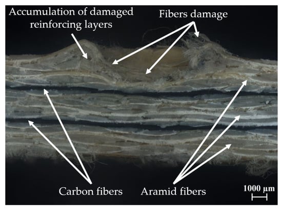
Figure 1.
Microscopic image of damage formed in a multilayered composite with hybrid reinforcement after impact of the hemispherical striker.
The total energy at impact is the sum of the remaining kinetic energy of the striker and the energy absorbed by the composite panel. The total energy during impact could be divided at the energy of the moving striker, energy absorbed by shear plugging, energy absorbed by deformation of secondary yarns, energy absorbed by tensile failure of primary yarns, energy absorbed by delamination, energy absorbed by matrix cracking, and energy absorbed by friction [22].
Considering energy absorption, the most commonly used reinforced material is aramid fibers [16]. These fibers can absorb a large amount of the impact energy before their breaking. Furthermore, aramid fibers are more elastic than, for example, carbon fibers [24]. They are characterized by high rigidity and orientation, and they are connected to each other by strong, dense hydrogen bonds [25]. They have a good strength to density ratio (specific strength). Strength expressed in this way for Kevlar® fibers is greater; that is, five times greater than steel [16]. The tensile curves of aramid fibers, similar to glass and graphite fibers, are approximately linear to break. Aramid fibers have a density 43% lower than that of glass fibers. Because of that, aramid fibers are particularly attractive for the production of many composites [25]. Energy-absorbing panels built using aramid fibers provide excellent protection against pistol bullets, revolver bullets, or fragmenting debris. Aramid fibers are one of the most important materials used for the production of energy absorbing panels [16]. However, in the application of energy absorbing panels, stiffness is also very important and should be enough high to prevent too much deformation after impact. To minimize that deformation employment of carbon fibers between aramid fibers, reinforcement layers could be a solution. However, carbon fibers have some disadvantages. The first of them is the brittle damage [26] after impact, which can be dangerous for nearby people. It is worth mentioning that the brittle damage in some cases can be desirable, especially during modelling of the separation process [27,28,29,30]. In this case, the process should be designed in such a way that the equivalent stress should exceed the allowable stress that appears in the direct cutting zone. Otherwise, the material being removed would not be separated. The proper combination of different reinforcing materials allows the composite to take advantage of each of the applied fibers [16,31,32]. Undoubted advantages of the carbon fiber reinforced polymer composites are their low density, good static and fatigue strength, high modulus of elasticity, resistance to abrasion, and corrosion resistance [25]. Because they consist almost exclusively of graphite, they are non-melting and chemically resistant. The heat resistance of carbon fibers is unique and outperforms any known materials in this respect, except graphite. The high values of Young’s modulus mean that this fiber is often used in hybrid composites to increase the stiffness of the structure [1,20].
Naik et al. [33] showed that the proper configuration of reinforcing layers in a glass–carbon epoxy composite could increase post-impact compressive force. It was also shown that the damage area in a hybrid composites depends on the reinforcing material configuration. Studies presented in [34] also show that the hybridization in glass–carbon epoxy composites provide greatly enhanced damage tolerance of these structures. The experimental results show that the hybrid composites can absorb more energy in the impact event compared with non-hybrid composites [35]. Aramid fibers are often used in the case of the personal protective equipment, such as helmets. In order to increase the amount of information about the examined object, experimental and numerical research is carried out [36,37,38]. In another paper [39], the impact resistance of composite panels reinforced with aramid fibers and the matrix made from various thermoplastic materials were compared. The authors of [40] compared the puncture resistance of the composites reinforced by 2D and 3D aramid fabrics. A further paper [41] presents the analysis of puncture resistance of aramid laminates on styrene–butadiene–styrene and epoxy resin matrix. The authors of [42] present the influence of the introduction of nanoclay into the resin on the increase of the maximum impact load of aramid fiber composite. Owing to the popularity of aramid fibers, research on composites with hybrid reinforcement (where aramid fibers were one of the used reinforcing materials) was also conducted. Research focused on a hybrid composite with reinforcement made of aramid and basalt fibers [43] shows that the use of both types of reinforcing materials in the proper configuration can increase the composite energy absorption during impact. The comparison of the hybrid composites with reinforced made of aramid and carbon fibers, based on the DI parameter (defined as the ratio between the damage propagation energy and the damage initiation energy), presented in the work of [35], showed that the highest value of this parameter was achieved for the composite in which reinforcing layers made of aramid fibers were used alternately with carbon fiber reinforcement layers. It was also noticed that the adjacent aramid fibers can also play a role in bridging the broken carbon fibers, which could improve the toughness of hybrid composites [35]. Studies on hybrid reinforcement made of aramid and carbon fibers in a sandwich structure [44] showed that the use of hybrid reinforcement increases the energy absorption of the composite during low speed impact. The authors of [44] obtained the highest values of absorbed energy in the case of a combination of three reinforcing layers of carbon fibers for one reinforcing layer of aramid fibers, and vice versa. However, the reduction of compressive strength after the impact was much smaller in the case where three reinforcing layers of aramid fibers for one reinforcing layer of carbon fibers was used. The damage area formed in the composite and its impact energy absorption during low velocity impact depend on the striker geometry [45]. Experimental and numerical research [45,46] showed that the influence of the striker geometry was changed with the impact velocity and the thickness of the composite.
The authors of that paper decided to assesses the influence of the striker geometry on the damage formed in the epoxy composite with hybrid reinforcement (made from aramid and carbon fabrics) after low velocity impact. Differences in the formed damage depending on the striker geometry were described. The authors of the present work decided to perform experimental and numerical research. The numerical calculations were performed in order to increase the amount of information about damage caused in the composite panel after impact of the strikers with different geometry; in particular, information about delamination between reinforcing layers. In Section 2, the authors present materials used as a reinforcement and as a matrix. The producing method of the composite and the adopted research methodology are also presented. The results of experimental research, which was carried out using four strikers with different geometries, are presented and discussed on the basis of microscopic images. In Section 3, the authors describe the process of preparation of the physical model. A methodology of modeling of the multilayered composite is presented. The damages caused in the composite plate as well as the phenomenon of delamination were presented and discussed. The authors present the values of the rebounded strikers’ kinetic energy and the relationship between the amount of damage in the reinforcing layers and the occurring diameter of the delamination area. The experimental and numerical results were compared. The differences in obtained results were discussed. Composite panel wear was considered in the local response.
2. Experimental Research
2.1. Methodology
During the experiment, hybrid composite panels reinforced with aramid and carbon fabrics were used. Aramid twill weave fabric used in the experiment with weight of 300 g/m2 was made from Twaron 2200 fibers. The second material used as a reinforcement was carbon twill weave fabric with a weight of 200 g/m2. It was made from Pyrofil TR30 S fibers. Mechanical properties of used fibers [47,48] are shown in Table 1.

Table 1.
Mechanical properties of used reinforcing fibers.
Hybrid panels consisted of 14 layers of reinforcing fabrics. They were arranged in the following combination: four layers of aramid fabric, one layer of carbon fabric, four layers of aramid fabric, one layer of carbon fabric, and four layers of aramid fabric. Epoxy resin LG285 was used as a matrix. The dedicated by manufacturer HG285 curing agent was mixed with resin with a 100:40 weight ratio. The epoxy matrix’s properties declared by the manufacturer [49] are shown in Table 2.
Table 2.
Properties of epoxy resin LG285 with HG285 curing agent.
The composite panels were manufactured by the hand-laminating method with vacuum support (−68 kPa of vacuum pressure). On the basis of the literature [6,16], four striker geometries were developed. Geometries of those strikers are shown in Figure A1. The adopted geometries allow the strikers to maintain a constant mass and to simulate the impact of various splinters. The required repeatability of the strikers’ impact kinetic energy can be achieved because of this. This repeatability is important because the researchers’ main goal is to determine the destruction images depending on the geometry of the strikers. They could be compared only when the impact energy was the same. Steel strikers with a mass of 49 g are shown in Figure 2.
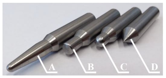
Figure 2.
Strikers used in experiment: A—ogival striker, B—blunt striker, C—hemispherical striker, D—conical striker.
The tests were realized using a hybrid electromagnetic launcher with a pneumatic support [26,50]. Initial air pressure value in an air tank and air valves were set up using a control panel. The test stand is shown in Figure 3.
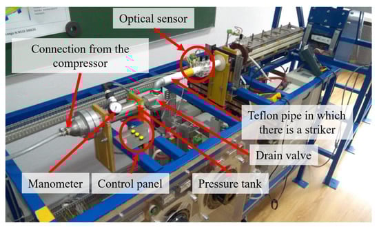
Figure 3.
Test stand used in experiment.
The striker velocity was measured using an optical gate connected to the oscilloscope. When the striker breaks the optical beam, the voltage spike could be observed on the oscilloscope. The next voltage spike is observed when the striker ends, breaking the optical beam. The experiments were carried out with 23.5 J of impact kinetic energy. This energy refers to sub ballistic velocities of the impact—such as collisions with fast moving elements [16]. The samples were glued to the 10 mm polyethylene base plate and hit three times by each striker. The polyethylene plate was exchanged with each composite sample. There is no deformation and destruction in the polyethylene plates after impact.
2.2. Results
The impact striker geometry assessment on the composite panels’ destruction was made on the basis of microscopic tests. The tests allowed the authors of this article to measure the diameter of the panel damages after impact. Because of the plastic character of aramid fiber destruction, the damages in the panel reflected the striker geometry, and the depth of the penetration could be calculated based on the cavity diameter and the geometry of the used striker. The results are shown in Table 3.
Table 3.
Average experimental results, depending on striker geometry.
The microscope images of the damage in composite panels presented in Figure 4 show the significant influence of the striker geometry. During the same impact, the same values of impact kinetic energy and destruction level in composite panels were limited from the matrix cracking in the blunt striker case to the almost complete penetration in the conical striker case. For the blunt striker, fibers absorbed almost all impact energy—there was no fiber damage. The cracked matrix is only one visible sign after impact in this case. That fact proved the high resistance of fiber reinforced composites on the impact of blunt elements. Cross sections of the samples after impact of the strikers are presented in Figure A2.
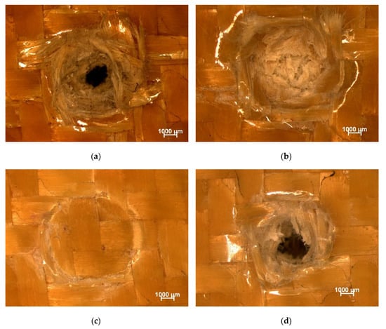
Figure 4.
Selected samples after impact of the striker: (a) conical, (b) hemispherical, (c) blunt, (d) ogival.
The destruction caused by a hemispherical striker was characterized by a high amount of compressed fibers. Around a newly created cavity, the characteristic bulge was formed. Fibers that were initially in the first layer of the impact area (in the center of panel) were then ripped out from the matrix. The broken and compressed fibers in this formed cavity were also visible. However, their amount was low, which proved that only fibers from the first layers were damaged, and fibers in the next layers were in good shape. There were no carbon fibers in the cavity, which suggests that the panel penetration is limited to the first four layers of the reinforced material. This was also confirmed by the calculated depth of penetration. It was circa 1.5 mm, which corresponds to the thickness of approximately of three layers of used aramid fabric. The cross section of the sample (Figure A2) also confirms that the penetration of the composite stops before the reinforcing layer made from carbon fibers was damaged.
The destruction caused by an ogival striker suggests much more sensitivity of the hybrid composite to the impact of such elements. The penetration depth was much higher compared with the penetration depth in the case of a hemispherical striker. The analysis of the microscopic images shows a lot of broken fibers in the created cavity. The broken fibers were visible as sticking out parts of the reinforcing fabric directed towards to the cavity. These fibers were also compressed at the boundary of the cavity. Like in the previous case, the first layer damage around the impact zone was also visible. The penetration depth in this case was 4.5 mm, which corresponds to the depth of the second reinforcing layer made from carbon fibers. At the bottom of the created cavity, there were no carbon fibers, which suggests that the second carbon reinforced layer was not penetrated. The cross section of the formed damage presented in Figure A2 also confirms that the second reinforcing layer made from the carbon fibers was not damaged.
The conical striker caused the largest destruction in the tested material. In this case, both the cavity diameter and its penetration depth were the largest. The destruction mechanism was the same as in the case of the ogival striker. Inside the formed cavity, it was possible to observe the parts of broken fibers. In the case of this striker, fibers’ deformation was also visible at the first layer around the impact area. This fact suggests that the conical geometry of the striker caused pushing fibers sideways of the creating cavity. The considered striker did not have enough energy to break fibers, so it stuck between them and pushed them sideways. The weave and weight of an applied reinforced fabric could have a critical meaning in strength aspect. As mentioned, fibers in the first layers were deformed, which confirm this fact. This also explained why damage caused by a conical and an ogival striker was largest compared with that of other strikers used.
3. Numerical Research
3.1. Preparation of Numerical Model
The numerical research was carried out using the finite element method and commercially available LS-PrePost/LS-Dyna (LSTC, Livermore, CA, USA) software. The multilayered composite could be modeled in a few scales. The modeling scale is related to the homogenization of the composite strength properties. In the case of modeling the composite as a one part, homogenization of the mechanical properties should be performed for the whole composite. Modeling in this scale makes it impossible to observe some processes occurring inside the composite material, for example, delamination, which, as mentioned in the introduction, is an energy absorbing process. A different approach is to model the composite with respect to the division on the reinforcing layers. In this approach, the strength properties should be homogenized in the level of the reinforced layer (used reinforcing fabric and the matrix). This modelling scale allows observing the delamination between the reinforcing layers. There is also the possibility to observe the movement between the adjacent reinforcing layers and the consideration of the friction between them. Woven composites could also be modeled with respect to the reinforcing fiber geometry. The mechanical properties of the fiber and the matrix are defined individually. Observation of the delamination process is also possible. Moreover, modelling in that scale allows to observe the deformation of each fiber and the friction between the fibers. If the modeling scale is more accurate, the physical model takes into account more energy absorbing phenomena. Therefore, the choice of the modeling scale and level of homogenization of strength properties has an impact on the obtained result. The selection of the modeling scale is related to use of the simplifications. Each simplification will be associated with the omission of some energy absorbing phenomenon. However, it should be remembered that, if the physical model is more advanced, the computational cost will be greater. Modeling of the composite with respect to the division on the reinforcing layers (homogenization of the strength properties in the reinforcing layer level) gives satisfactory results, which are in accordance with experimental research [51]. It was decided to model the composite material in a macro scale. It means that each reinforced layer was modeled as an individual part. This approach is widely used [51,52,53,54] in the case of impact analysis. A flat surface with dimensions of 50 × 100 mm (height × width) was created, and then it was discretized into the finite elements. The surface was divided into Belytschko–Tsay type shell elements with “hourglass” control based on stiffness. A total of 5000 Belytschko–Tsay shell elements were created in this way. It was assumed that the thickness of each layer, regardless of the reinforced material, was 0.5 mm, which allowed the physical model to achieve the overall thickness of the composite used in the experiment (7 mm). On the basis of this assumption, 13 subsequent surfaces were created, spaced 0.5 mm from the previous layer along the axis perpendicular to the surface of the layers. The composite model created in this way consists of 70,000 shell elements. As a composite material model, the MAT58 *MAT_LAMINATED_COMPOSITE_FABRIC [55] was used. This model requires the definition of homogeneous strength properties of the used materials. Taking into account the destruction of the physical model, the finite elements are controlled by the ERODS parameter. The ERODS parameter is calculated based on the deformation in defined fiber directions in the reinforced plane and on the shear deformation. In this material, model stress increases nonlinearly until the maximum strength is reached (XT). When the maximum strength is reached, the stress is reduced by the SLIMx factor and held until material reaches the strain specified by the ERODS parameter. When strain reaches the value defined as an ERODS, the finite element is deleted [56]. The typical stress–strain curve for the selected MAT58 composite material model is shown in Figure 5.
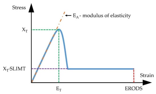
Figure 5.
Typical stress—strain curve for the selected MAT58 composite material model.
On the basis of the research [56], ERODS = 0.4 was adopted. Because the values of SLIMx coefficients do not have their physical interpretation [57], their value was adopted in accordance with the recommendations [55]. The impact of individual factor values on the convergence with an experimental solution is presented, among others, in the work of [56]. The used material properties of epoxy composites with carbon and aramid reinforcement (in two directions) are shown in Table 4.
Table 4.
Mechanical properties of epoxy composites reinforced by carbon and aramid fibers [58].
The delamination is an important energy absorption mechanism in the case of low velocity impact [51]. In case of the modeling approach used in research, the connection between successive layers of reinforcing material can be modeled in several ways [52,59,60,61]. Modeling of the bonding connection between adjacent reinforcing layers could be realized using cohesive elements [54,62]. This approach involves inserting additional cohesive elements between elements of adjacent reinforcing layers. In the initial phase, these elements may have zero thickness. The behavior of the cohesive elements can be described, for example, using a bilinear curve. These curves describe the dependence between the cohesive element stresses from its deformation [54,59,60,62]. If the cohesive element is not damaged, its stiffness is constant. However, if an element is damaged, its stiffness decreases as deformation increases [62]. The use of cohesive elements requires high computational costs [52]. A broader description of this type of connection has been described, among others, in the literature [54,59,60,62]. The second approach of modeling the bonding connection between the adjacent reinforcing layers is the use of the bilateral constraints (tiebreak contact type). This contact allows for the simplification of crack propagation based on the cohesive element [51]. After reaching normal and shear stresses, damage is a linear function of the distance between points that were initially in contact. After reaching the defined critical crack opening, the bonding connection is broken and further contact behaves like unilateral constraints. This approach does not require the use of additional elements and, shown in the work of [51], this bonding connection modelling method give results in accordance with experimental research. In the conducted research, it was decided to use the bilateral constraint contact with strength criterion (*AUTOMATIC_SURFACE_TO_SURFACE_TIEBREAK [63]). This contact type behaves like a bonded connection before the strength criterion is exceeded. After exceeding the strength criterion, this contact behaves like a unilateral constraint contact without a bonded connection. There are several possibilities to define the bonded connection using the selected contact type. In the case of shell elements, the definition OPTION = 8 is most commonly used [59]. This option requires to define the critical normal and shear stresses in a bonding connection. The critical normal stress assumed in the physical model equals Sn = 75 MPa [49] and the critical shear stress equals Ss = 44 MPa [59], respectively. The friction coefficient between reinforced layers was defined as 0.18 [52,64,65].
Additionally, one more part created in the presented model was a polyethylene base plate, to which the tested samples were glued. The plate was discretized using eight node solid elements with one integration point. The edge length of each element was 1 mm. The base plate model consisted of 50,000 solid elements. It was decided to choose the linear elastic material model (*MAT_ELASTIC [55]). The applied mechanical properties of polyethylene [66] are shown in Table 5. The contact between the last layer of the composite and the polyethylene base plate was modeled using the unilateral constraint contact (*AUTOMATIC_SURFACA_TO_SURFACE). The value of 0.29 was adopted as a friction coefficient [66].
Table 5.
Mechanical properties of polyethylene.
During the experiment, four different types of strikers were used (Figure 2). Their geometries were made in CAD software (Autodesk Inventor Professional 2019), and then they were imported and discretized using eight nodal solid elements. These elements were given mechanical properties corresponding to the steel and treated as non-deformable using the *MAT_RIGID [55] material model. The strikers were placed opposite to the first layer of the laminate. An initial velocity of the striker V0 = 31 m/s was set. The boundary condition assigned to the model blocked all degrees of freedom (translational and rotational) for all nodes of a polyethylene base plate at the side opposite to the side of contact with the composite. The contact between the non-deformable striker and the composite layers was defined as *AUTOMATIC_SURFACE_TO_SURFACE (unilateral constraint). The values of static and dynamic friction coefficients between the striker and the reinforcing layers were set as 0.18 [52,64,65]. The schematic diagram of the created model is shown in Figure 6a. The prepared model is shown in Figure 6b.
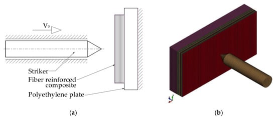
Figure 6.
Numerical research: (a) schematic diagram, (b) physical model.
3.2. Numerical Results
Damage caused by the strikers with various geometries at different instances of the simulation (up to reach the maximum depth of the penetration) is shown in Figure A3, Figure A4, Figure A5 and Figure A6. Each reinforcing layer is marked by a different color. The cross sections of damaged areas owing to the impact of various strikers are shown in Figure 7. The direction of the impact is marked using a white arrow.
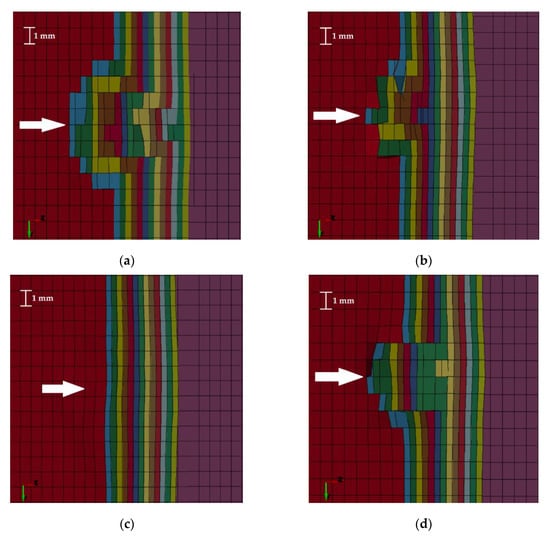
Figure 7.
Cross sections of damaged areas caused by (a) conical striker, (b) hemispherical striker, (c) blunt striker, and (d) ogival striker.
The numerical results have shown that the largest damages (Figure 7a) occurred when a conical striker was used. The smallest damage occurred in the case of a blunt striker (Figure 7c), which corresponds to the experimental results. The area of damage for each striker geometry is different. The damage caused by impact of the striker with a conical end (Figure 7a) is characterized by the formation of a narrowing taper. In each subsequent damaged layer, the number of degraded elements decreased to form a characteristic cone. These damages are the largest among the analyzed cases. The sharp end of the conical striker penetrating successive layers of material caused rapid damage to the individual elements in subsequent reinforcing layers, which contributed to the weakening of the entire structure.
The damage caused by the hemispherical striker (Figure 7b) was less extensive compared with the damage caused by the conical striker. The resulting damage does not form a characteristic cone. The largest damages were observed in the first four layers of reinforcement. The elements that were not deleted are arranged in a chaotic manner. It can be observed that the elements in the second layer of reinforcement in the impact area are not completely destroyed, which can be interpreted as the fiber compression inside the formed crater (as mentioned in the chapter about experimental research). The other two damaged layers (5 and 6) were minimally damaged—individual elements were deleted. The blunt striker did not cause any visible damage in the reinforcement material (Figure 7c). The ogival striker caused the most damage (Figure 7d) in the first two layers of the material. Penetration of subsequent layers was characterized by the removal of the same number of finite elements until the striker energy was too low to damage the next layer. The last of the damaged layers degraded in the form of individual elements.
The colored map of Tresca stress presented in Figure 8 showed that the primary yarns (at the direction defined as a fiber direction—X and Y axis) carried the largest load. The secondary yarns were much less loaded. This conclusion was confirmed in the work of [16]. In addition to the analysis of destruction, which was performed based on the Figure 7c, the value of Tresca stresses shown in Figure 8 suggests that the matrix could be damaged. As shown in Table 2, the tensile strength of the matrix is 75–85 MPa. Tresca stress at the edge of impacting striker (on the first layer of reinforcement) was much higher (92.5–110 MPa). This analysis suggests that the matrix could be damaged, as in the case of the experimental research (matrix cracking). The average diameter of this area was 7.5 mm.
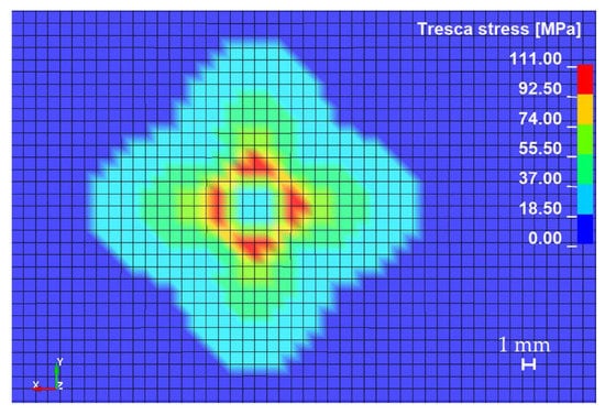
Figure 8.
Colored map of Tresca equivalent stress on the first layer of reinforcement in case of blunt striker impact.
Table 6 shows the diameters of the cavities and depth of the penetration of the damages created by the impact of strikers with different geometries. The measurement of cavity diameters was done between the nodes of the elements at the first layer, which were not deleted after impact. The biggest damage in the first layer of reinforcing material was observed for the case in which the conical striker hits the composite. The second largest diameter of the damaged area was observed for the case in which a hemispherical striker was used. The diameter of the damaged area in this case was slightly larger than in the case of the impact of the ogival striker. The depth of penetration was based on the number of damaged reinforced layers—0.5 mm of damage for each damaged layer.
Table 6.
Numerical results, depending on striker geometry.
The largest depth of penetration was observed for the case in which the composite panel was hit by a conical striker. As a result of its impact, 12 layers of reinforcing material were damaged. The impact with an ogival striker resulted in damage to eight layers of reinforcing material. In the case of a hemispherical striker, six layers of reinforcing material were damaged. However, these damages were different. The damage created did not resemble a cone geometry. As it was mentioned, the individual elements were deleted from 5 and 6 damaged layer (damage area was smaller than used striker). Due to that, this two layers were not considered in depth of penetration calculation. For the impact on the composite material with a blunt striker, no damage was observed in the reinforcing material, but small deformation was observed.
The graph representing kinetic energy of the striker depending on its geometry is shown in Figure 9. The fastest braking of the striker occurred with a blunted one. This striker was rebounded from the composite panel, obtaining the kinetic energy of about 16 J. This testified that a small amount of energy was absorbed by the composite panel. The hemispherical striker was rebounded from the panel, obtaining a value of the kinetic energy of about 8.5 J. The braking of the striker before it was rebounded proceeded with the same intensity as in the case of a blunt striker, despite the damage caused in the reinforcing layers. A smaller value of the rebounded kinetic energy of the striker is associated with a greater amount of energy absorbed by the composite. Conical and ogival strikers had the lowest kinetic energy after rebounded (approximately 2 J). Despite the differences in the strikers’ braking intensity, they were stopped at the same time and had similar kinetic energy after being rebounded. The curve depicting the kinetic energy value of the ogival striker has a distinctive area of braking corresponding to the level of material penetration. The first change in the angle of inclination of this curve at the time t ≈ 0.1 ms is associated with the first damage to the material. Another angle change in the time t ≈ 0.2 ms is associated with the end of damaging of the reinforcement layers. In the next phase, material was deformed without damaging and striker was inhibited and rebounded. Braking of the conical striker was the gentlest, which was probably because of the fact that its pointed end easily damaged the elements in the subsequent layers of the composite. It is interesting that the conical and ogival strikers, despite large differences in the damage caused, were characterized by the same value of the kinetic energy after rebound.
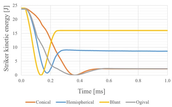
Figure 9.
Kinetic energy of strikers during impact depending on their geometry.
3.3. Comparison of Experimental and Numerical Research
The results of the conducted experimental and numerical research were compared based on the diameters and depth of penetration of cavities formed after impact of the strikers. Figure 10 shows the comparison of the diameters of the cavities formed after the impact.
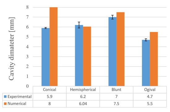
Figure 10.
Comparison of cavity diameter formed after impact.
The damage caused by the blunt striker in the experiment (Figure 4c) is limited to the matrix cracking. The diameter of the resulted crack corresponds to the diameter of the edge of the impacting striker. The resulting damage did not damage the reinforcing layer in any way. Performing numerical research in the selected scale makes it impossible to capture phenomena like matrix cracking, but proper analysis of the stress map could bring valuable conclusions. As discussed in the numerical research results, the obtained Tresca stress value suggests that the matrix was damaged, as in the case of the experimental research. The measured diameter of damaged area was almost the same as in the case of the experimental research. Another discrepancy between the experimental and numerical research is in the case of hitting the composite by the conical striker. During the experimental research, the pointed tip of the cone stuck between the individual fibers, pushing them sideways. Fibers pushed sideways constituted resistance for the striker, and tightened on it, thus reducing damage caused in subsequent layers. In the case of numerical research, individual fibers were not considered. Each reinforcing layer was modeled as a single part with directionally assigned properties. The indicated directions corresponded to the directions of the fibers in the used reinforcing fabric, however, the modeling of the reinforcement in this way makes it impossible to imitate the mechanism of deformation of individual fibers. Finite elements hit directly by the tip of the cone were quickly removed. When an element was removed, it stopped absorbing the energy, so material did not resist as much energy as in the case of the experiment. This fact could have an effect for the larger amount of destruction in the case of the numerical research. The same remark applies to the discrepancy between the results obtained for the ogival striker.
Figure 11 shows the comparison of the depths of penetration obtained as a result of the provided experimental and numerical research. For conical and hemispherical strikers, the depths of penetration obtained as a result of numerical research were larger than in the experimental research. In the case of the experimental research, depths were determined indirectly based on the diameter of the formed cavity and the striker geometry. This method could be subject to a large error, resulting from the lack of information about the damaged fibers under the visible layer of damaged reinforcement. Additionally, in the case of the numerical research, elements removed during calculations do not constitute any resistance for the strikers’ movement at a later stage. In real conditions, the damaged fibers were still in the forming cavity, clamping on the striker, or accumulating in front of its forehead, thus affecting the formation of further damage. Figure 12 shows the percentage variation between the results obtained from the experimental and numerical research.
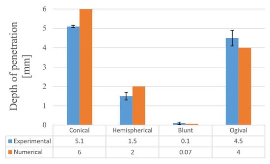
Figure 11.
Comparison of depth of penetration after impact.
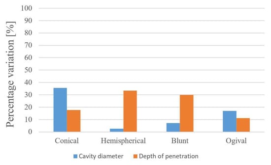
Figure 12.
Percentage variation between the results obtained from experimental and numerical research.
3.4. Delamination
As mentioned in the Introduction, in the case of multilayer composite materials, the energy is absorbed not only as a result of the destruction of reinforcing fibers, but also as a result of the destruction of connections between successive reinforcing layers (delamination). The inclusion of this process in numerical simulations has an effect on the obtained results. Figure 13, Figure 14 and Figure 15 show maps of the delamination areas between selected layers as an effect of the striker’s impact. The areas marked in red (for which the parameter value was 1) were the areas where the bonded connection between layers was broken (delamination occurs).
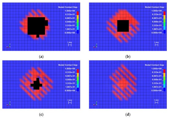
Figure 13.
Colored maps of delamination areas after impact of the conical striker between layers: (a) 1 and 2, (b) 5 and 6, (c) 7 and 8, (d) 13 and 14.
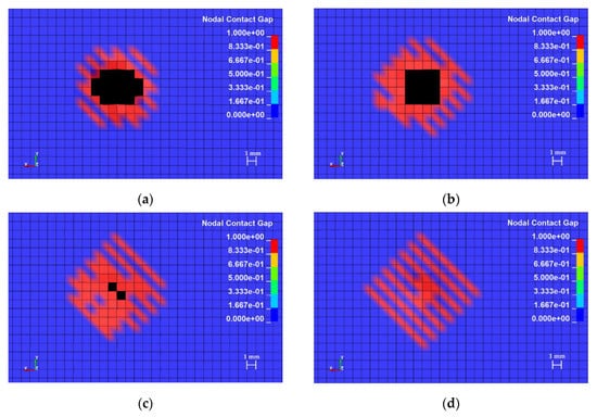
Figure 14.
Colored maps of delamination areas after impact of the ogival striker between layers: (a) 1 and 2, (b) 5 and 6, (c) 7 and 8, (d) 13 and 14.
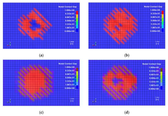
Figure 15.
Colored maps of delamination areas after impact of the blunt striker between layers: (a) 1 and 2, (b) 2 and 3, (c) 9 and 10, (d) 13 and 14.
The areas of material delamination resulting from impact by a conical striker indicate an increase of the diameter of delamination area in layers with a smaller amount of destruction in the reinforcing material. In the area of the first reinforcing layers, where the damage in the material is the biggest, the delamination covered a narrow area around the damage (Figure 13a). The delamination area increases with successive layers of reinforcing material, which is accompanied by a reduction in the number of deleted elements in reinforcing layers. In the case of the layers that were not damaged, as a result of the striker impact, the diameter of the area where delamination occurred was slightly increased.
In the case of the composite hit by an ogival striker, the delamination area occurring between the first and second reinforcement layer (Figure 14a) was smaller than in the case of the conical striker. The delamination area increased with each next reinforcing layer, until reaching a diameter of 14 mm between layer 13 and 14 of the reinforcing material. Concentration of the delamination was observed in places located in the axis of impact of the striker. As in the case of the conical striker, if more damage in reinforced layer was observed, then the less delamination occurs between this and next reinforcing layer.
The colored maps presented in Figure 15 indicate that, in the composite material that was hit by a blunted striker, the internal structure was damaged—delamination between the reinforcement layers. The diameter of the delamination area is almost the same over the entire thickness of the composite.
The detection of areas in which the material structure is damaged, like a delamination, is particularly important because this damage changes the behavior of the entire composite material and affects its mechanical properties. In the case of the practical application of multilayered composite materials, the lack of detection of such material damage can lead to dangerous situations in which there may be a serious failure, loss of load capacity, or reduction of the strength of elements working under high pressure, which can directly lead to the health and life threat of people working near such elements. The delamination is particularly difficult to detect because they are usually not visible and their detection requires specialized tests. An interesting solution for monitoring such damage is the triboelectric sensor. These sensors do not require external power supply and they are mounted directly on the composite material. The results presented in the work of [67] showed it can be observed that the voltage outputs of the sensor are proportional to the extension of the damage in the composite. The triboelectric sensor can be used to predict the damage state of the composite plates and the size of the delamination caused by impacts of the strikers [67].
Figure 16 showed the diameters of the measured delamination areas between first and second reinforced layers, as well as the thirteenth and fourteenth. It is characteristic for all analyzed cases that the delamination areas increase with each subsequent reinforced layer. It is also worth noting the relationship between diameter of delamination area and the damage in the reinforced layer. If the damaged area was bigger, than the delamination area was smaller. The impact with the conical striker caused the largest damage in the reinforcing layers, but the delamination area was the smallest among the analyzed cases. The impact with the blunt striker caused the smallest damage in the reinforcing layers, but the delamination area was the biggest among the analyzed cases.
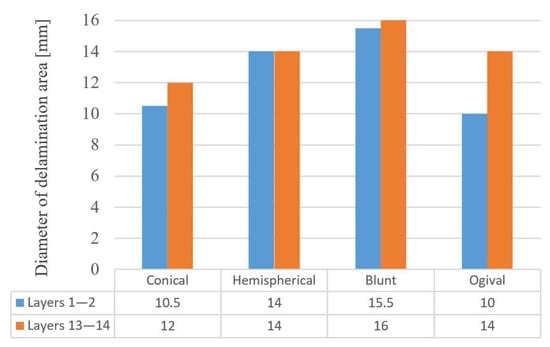
Figure 16.
Diameters of delamination areas between reinforcement layers 1 and 2 and 13 and 14.
4. Discussion
The blunt striker did not cause any visible damage in the reinforcing layers, however, the area of delamination was largest between analyzed cases. As mentioned, the delamination process absorbs part of the impact energy. The main part of the energy difference between the initial kinetic energy of blunt striker and the kinetic energy after its rebound is connected with the energy absorbing delamination process. Including the phenomenon of delamination in numerical studies allows the scientist to estimating the extent of the structure damage. It should be remembered that not every damage that was caused is immediately visible, as was the case of a panel impacted by the blunt striker. The reinforcing material was not damaged, however, the composite structure was damaged, which affects its strength. The same fact applies to cases in which other strikers were used. As shown by numerical research, the real areas of damage were much larger than that estimated on the diameter of the cavities formed after impact in experimental research. Experimental research presented in another paper [68] confirms that the delamination area grows with each next reinforcing layer from the impact point. The shape of the delamination areas was also similar to the shape that could be observed in experimental research [22]. It is worth to noting that delamination areas can be reduced by adding, for example, nanofibers. Research presented in another paper [62] showed that the incorporation of polycaprolactone nanofibers reduces the delaminated area by about 27% in glass fiber reinforced polymer composites. Research presented in another paper [62] also confirms that the epoxy glass composites reinforced with polycaprolactone nano fibers are less susceptible to impact damage than the same composites without polycaprolactone nano fibers.
The comparison of rebounded energy value in the case of conical and ogival strikers with damages caused by those strikers in composites suggests that the energy was absorbed in different ways, depending on the strikers’ geometry. Rebounded energy was the same, but damaged was different. In the case of the conical striker, damage in reinforced layers was bigger. In the case of the ogival striker, the delamination areas was bigger, which suggests that the delamination absorbed a higher part of the impact energy than in the case of the conical striker, which causes the smallest damage in the reinforcement layers.
In the case of the composite made from glass fibers and polyester resin [69], it was noted that the largest areas of damage were obtained when the conical and hemispherical strikers were used. In the conducted research, the largest diameter of damage in the first reinforcing layer was also noted for these two strikers. In the case of the research presented in a further paper [69], the composite material absorbed different amounts of the impact energy depending on the striker geometry. The amount of absorbed energy in descending order was as follows: conical striker, ogival striker, hemispherical striker, and blunt striker. The same results were obtained for carbon epoxy composite (impact energy up to 6 J) in another paper [70]. In the conducted numerical research, the same order was observed (Figure 9). Carbon fiber reinforced composite in the case of the blunt striker impact (50 J of the impact energy) absorb almost the same amount of impact energy as in the case of the conical striker [45]. In the conducted research, the hybrid composite absorbs different amounts of impact energy in the case of those strikers. In the case of the conical striker, the composite absorbs a few times more impact energy than in the case of the blunt striker. In the case of the analyzed composites, the plastic behavior of aramid fibers causing the damage caused by the strikers with different geometries is much more diverse than in the case of, for example, the composite made from carbon fibers, the damage of which is brittle [69,70].
The conducted experimental and numerical research indicates that the process of energy absorption in composite panels is complex. In the case of the experimental research, energy was absorbed by all factors listed in the introduction. Owing to the adopted modeling scale, the impact energy in the case of numerical research could not be absorbed by friction between the fibers (inside the reinforcing layer). The energy was absorbed by the friction between the striker and the reinforcing layers and by the friction between the adjacent reinforcing layers. The numerical results present that the delamination absorbed some of the impact energy, which is best seen in the case of the blunt striker. The presented Tresca equivalent stress (Figure 8) indicates that the primary yarns were subjected to the highest stress; however, in the adopted modeling scale, it is difficult to clearly divide the energy absorbed by the reinforcing layer into the energy absorbed by the destruction of primary yarns, deformation of secondary yarns, and shear plugging. The difference between energy absorption in the case of experimental research and absorption in the numerical research (which results from the adopted modeling scale) obviously has an impact on the result. The lack of consideration of some energy absorbing phenomena increases the damage in the composite panel.
It was stated that carrying out numerical research simultaneously with experimental research can significantly affect the quality of the obtained conclusions. Appropriate model preparation and consideration of physical phenomena occurring in the analyzed material can provide a lot of important information. The calibration of the numerical model and its verification based on the performed experimental research is also important. If the model is considered as a satisfactory, it can be used to observe phenomena that are hard or even impossible to observe during the experiment. In the conducted research, such a phenomenon was delamination areas between reinforcing layers. In the case of multilayered composites, it is very important to use the right modeling scale, because observing some phenomena on the model prepared in the wrong scale is not possible. During the interpretation of the numerical research results, the simplifications used should be taken into account, particularly simplifications resulting from the used modeling scale. A compromise between which phenomena can be observed and the time of calculations should be found. Preparing an increasingly detailed model, one should take into account that the calculation time may increase several times.
5. Conclusions
On the basis of research, it was found the strikers’ geometry has a significant effect on the damaged microscopic images. The greatest damage was observed for the conical striker (the panel was almost pierced). During the impact, those strikers stuck between the fibers, and pushed them sideways. In the case of such a material penetration mechanism, stretching of the fibers absorbs a smaller part of the impact energy. The fibers in this case are pushed sideways and pressed on the margin of the formed cavity. In the case of a hemispherical striker, much lower damage was observed. The damage caused by this striker was characterized by a large amount of crushed fibers, compressed inside the formed cavity. It is worth noting that the depth of penetration in the case of this type of striker was much smaller than in the case of strikers with the cone-like geometry. The smallest damage was observed for a blunt striker (matrix cracking only). In the analyzed case, there were no damages in the reinforcing layers, but only, as numerical research showed, the integrity of the bonded connection between the reinforcing layers was broken (delamination). The numerical investigations presented that the largest diameters of the delamination areas occur on the side opposite to the impact side. The measurements of the diameters of delamination areas in subsequent layers indicate that these delamination areas form a cone with a base located on the side opposite to the impact side. It was also noticed that the larger delamination areas between the reinforcing layers were between layers where there was smaller damage in the reinforcement. As could be observed in the experimental research, the penetration level in the case of two strikers stops at the depth corresponding to the place when carbon reinforcement layers have been used, which could testify that the use of hybrid structures with carbon and aramid fibers could increase the stiffness of the panels and increase the puncture resistance of the composite.
Author Contributions
Conceptualization, S.S. and M.S.; Formal analysis, S.S.; Funding acquisition, S.D.; Investigation, S.S., M.S., J.K., J.D., and S.D.; Methodology, S.S. and M.S.; Software, S.S.; Supervision, S.D.; Validation, S.S., M.S., J.K., and S.D.; Visualization, S.S.; Writing—original draft, S.S. and J.K.; Writing—review & editing, S.S. and J.K. All authors have read and agreed to the published version of the manuscript.
Funding
This work was financially supported by statutory funds from the Faculty of Mechanical Engineering of Silesian University of Technology in 2019.
Acknowledgments
Calculations were carried out using the computer cluster Ziemowit (https://www.ziemowit.hpc.polsl.pl) funded by the Silesian BIO-FARMA project No. POIG.02.01.00-00-166/08 in the Computational Biology and Bioinformatics Laboratory of the Biotechnology Centre in the Silesian University of Technology.
Conflicts of Interest
The authors declare no conflicts of interest.
Appendix A
Strikers used in experimental research were manufactured from S235JR steel rod by machining.

Figure A1.
Geometries of developed strikers: (a) ogival, (b) blunt, (c) hemispherical, (d) conical.
Appendix B
Microscopic images of damage in the composite panels with the hybrid reinforcement are shown in Figure A2. The jagged fragments of the fibers at the side opposite to the impact side are the result of the cutting process.

Figure A2.
Cross sections of the damage formed in the composite panels after impact of the striker: (a) conical, (b) hemispherical, (c) blunt, (d) ogival.
Appendix C

Figure A3.
Damage caused by the conical striker at different instances of the simulation: (a) time = 0.1 ms, (b) time = 0.2 ms, (c) time = 0.3 ms, (d) time = 0.35 ms.

Figure A4.
Damage caused by the hemispherical striker at different instances of the simulation: (a) time = 0.05 ms, (b) time = 0.1 ms, (c) time = 0.15 ms, (d) time = 0.2 ms.

Figure A5.
Damage caused by the blunt striker at different instances of the simulation: (a) time = 0.05 ms, (b) time = 0.1 ms, (c) time = 0.12 ms, (d) time = 0.15 ms.

Figure A6.
Damage caused by the ogival striker at different instances of the simulation: (a) time = 0.1 ms, (b) time = 0.2 ms, (c) time = 0.3 ms, (d) time = 0.35 ms.
References
- Jureczko, M. Multidisciplinary Optimization of Wind Turbine Blades with Respect to Minimize Vibrations. In Recent Advances in Composite Materials for Wind Turbine Blade; Attaf, B., Ed.; The World Academic Publishing Co. Ltd.: Hong Kong, China, 2013; pp. 129–146. [Google Scholar]
- Pawlak, M. The Acceleration Severity Index in the impact of a vehicle against permanent road equipment support structures. Mech. Res. Commun. 2016, 77, 21–28. [Google Scholar] [CrossRef]
- Szymiczek, M. Selection of engineering materials on lightweight energy-intensive shields. Poly. Process. 2016, 22, 149–157. [Google Scholar]
- Chatys, R.; Kleinhofs, M.; Panich, A.; Kisiel, M. Modeling of mechanical properties of composite structures taking into account military needs. AIP Conf. Proc. 2019, 2077, 1–8. [Google Scholar] [CrossRef]
- MIL-STD-662F Military Standard: V50 Ballistic Test for Armor; Department of Defense: Washington, DC, USA, 1997.
- STANAG 4569 Protection Levels for Logistic and Light Armoured Vehicle Occupants; NATO/PFP Unclassified; NATO: Brussels, Belgium, 1998.
- Rojek, M.; Szymiczek, M.; Stabik, J.; Mężyk, A.; Jamroziak, K.; Krzystała, E.; Kurowski, J. Composite materials with the polymeric matrix applied to ballistic shields. Arch. Mater. Sci. Eng. 2013, 63, 26–35. [Google Scholar]
- Machoczek, T.; Mężyk, A.; Duda, S. Shaping the dynamic characteristics of military special vehicles. Solid State Phenom. 2016, 248, 192–203. [Google Scholar] [CrossRef]
- Krzystała, E.; Kciuk, S.; Mężyk, A. Identification of Hazards for the Crew of Special Vehicles during an Explosion; Wydawnictwo Naukowe Instytutu Technologii Eksploatacji: Gliwice, Poland, 2012. [Google Scholar]
- Jureczko, M.; Mężyk, A. Multidisciplinary optimization of wind turbine blades. In Proceedings of the Fourth European & African Conference on Wind Engineering, EACWE 4, Prague, Czech Republic, 11–15 July 2005; Naprstek, J., Ed.; Institute of Theoretical and Applied Mechanics, Academy of Sciences of the Czech Republic: Prague, Czech Republic, 2005; pp. 40–46. [Google Scholar]
- Cegła, M.; Habaj, W.; Stępniak, W.; Podgórzak, P. Hybrid ceramic-textile composite armour structures for a strengthened bulled-proof vest. Fibres Text. East. Eur. 2015, 23, 85–88. [Google Scholar]
- Lane, R.A. High performance fibers for personnel and vehicle armor systems. Putting a stop to current and future threats. Amptiac Q. 2005, 9, 3–9. [Google Scholar]
- Radziszewski, L. Final Ballistics of Small-Caliber Ammunition When Shooting at Selected Targets; Wydawnictwo Politechniki Świętokrzyskiej: Kielce, Poland, 2007. [Google Scholar]
- Czapla, T.; Wrona, J. Technology development of military applications of unmanned ground vehicles. Stud. Comput. Intell. 2013, 481, 293–309. [Google Scholar] [CrossRef]
- Nabaglo, T.; Kowal, J.; Jurkiewicz, A. Construction of a parametrized tracked vehicle model and its simulation in MSC.ADAMS program. J. Low Freq. Noise Vib. Act. Control 2013, 32, 167–173. [Google Scholar] [CrossRef]
- Jamroziak, K. Identification of Materials Properties in Terminal Ballistics; Oficyna Wydawnicza Politechniki Wrocławskiej: Wroclaw, Poland, 2013. [Google Scholar]
- Wersa, E.; Seweryn, A.; Szusta, J.; Rak, Z. Fatigue testing of transmission gear. Maint. Reliab. 2015, 17, 207–214. [Google Scholar] [CrossRef][Green Version]
- Ostachowicz, W.M.; Krawczuk, M.; Palacz, M. Detection of delamination in multilayer composite beams. Key Eng. Mater. 2003, 245–246, 483–490. [Google Scholar] [CrossRef]
- Palacz, M. Spectral methods for modelling of wave propagation in structures in terms of damage detection—A review. Appl. Sci. 2018, 8, 1124. [Google Scholar] [CrossRef]
- Boczkowska, A.; Kapuściński, J.; Lindemann, Z.; Witemberg-Perzyk, D.; Wojciechowski, S. Composites; Oficyna Wydawnicza Politechniki Warszawskiej: Warsaw, Poland, 2000. [Google Scholar]
- Kang, T.J.; Kim, C. Impact energy absorption mechanism of largely deformable composites with different reinforcing structures. Fibers Polym. 2000, 1, 45–54. [Google Scholar] [CrossRef]
- Naik, N.K.; Shrirao, P.; Reddy, B.C.K. Ballistic impact behaviour of woven fabric composites: Formulation. Int. J. Impact Eng. 2006, 32, 1521–1552. [Google Scholar] [CrossRef]
- Hogg, P.J. Composites for ballistic applications. Proc. Compos. Process. 2003, 1–11. [Google Scholar]
- Sławski, S.; Szymiczek, M.; Domin, J. Influence of the reinforcement on the destruction image of the composites panels after applying impact load. AIP Conf. Proc. 2019, 2077, 1–10. [Google Scholar] [CrossRef]
- Fejdyś, M.; Łandwijt, M. Technical fibres reinforcing the composite material. Tech. Tex. 2010, 18, 12–22. [Google Scholar]
- Sławski, S.; Szymiczek, M.; Chmielnicki, B. Puncture resistance of epoxy-carbon composites subjected to ageing process in the thermal shock conditions. Polym. Process. 2018, 24, 52–60. [Google Scholar]
- Kaczmarczyk, J.; Kozłowska, A.; Grajcar, A.; Sławski, S. Modelling and microstructural aspects of ultra-thin sheet metal bundle cutting. Metals 2019, 9, 162. [Google Scholar] [CrossRef]
- Kaczmarczyk, J. Modelling of guillotine cutting of a cold-rolled steel sheet. Materials 2019, 12, 2954. [Google Scholar] [CrossRef]
- Xiong, X.; Xiao, Q. Meso-scale simulation of concrete based on fracture and interaction behavior. Appl. Sci. 2019, 9, 2986. [Google Scholar] [CrossRef]
- Cho, J.-R. A numerical evaluation of SIFs of 2-D functionally graded materials by enriched natural element method. Appl. Sci. 2019, 9, 3581. [Google Scholar] [CrossRef]
- Wróbel, G.; Szymiczek, M.; Kaczmarczyk, J. Influence of the structure and number of reinforcement layers on the stress state in the shells of tanks and pressure pipes. Mech. Compos. Mater. 2017, 53, 165–178. [Google Scholar] [CrossRef]
- Ochelski, S. Experimental Methods of Construction Composites Mechanics; Wydawnictwa Naukowo-Techniczne: Warsaw, Poland, 2004. [Google Scholar]
- Naik, N.K.; Ramasimha, R.; Arya, H.; Prabhu, S.V.; ShamaRao, N. Impact response and damage tolerance characteristics of glass–carbon/epoxy hybrid composite plates. Compos. Part B Eng. 2001, 32, 565–574. [Google Scholar] [CrossRef]
- Hosur, M.V.; Adbullah, M.; Jeelani, S. Studies on the low-velocity impact response of woven hybrid composites. Compos. Struct. 2005, 67, 253–262. [Google Scholar] [CrossRef]
- Ying, S.; Mengyun, T.; Zhijun, R.; Baohui, S.; Li, C. An experimental investigation on the low-velocity impact response of carbon-aramid/epoxy hybrid composite laminates. J. Reinf. Plast. Compos. 2017, 36, 422–434. [Google Scholar] [CrossRef]
- Rodríguez-Millán, M.; Ito, T.; Loya, J.A.; Olmedo, A.; Miguélez, M.H. Development of numerical model for ballistic resistance evaluation of combat helmet and experimental validation. Mater. Des. 2016, 110, 391–403. [Google Scholar] [CrossRef]
- Tan, L.B.; Tse, K.M.; Lee, H.P.; Tan, V.B.C.; Lim, S.P. Performance of an advanced combat helmet with different interior cushioning systems in ballistic impact: Experiments and finite element simulations. Int. J. Impact Eng. 2012, 50, 99–112. [Google Scholar] [CrossRef]
- Tham, C.Y.; Tan, V.B.C.; Lee, H.P. Ballistic impact of a KEVLAR® helmet: Experiment and simulations. Int. J. Impact Eng. 2008, 35, 304–318. [Google Scholar] [CrossRef]
- Mayer, P.; Pyka, D.; Jamroziak, K.; Pach, J.; Bocian, M. Experimental and numerical studies on ballistic laminates on the polyethylene and polypropylene matrix. J. Mech. 2019, 35, 187–197. [Google Scholar] [CrossRef]
- Bandaru, A.K.; Chavan, V.V.; Ahmad, S.; Alagirusamy, R.; Bhatnagar, N. Ballistic impact response of Kevlar® reinforced thermoplastic composite armors. Int. J. Impact Eng. 2016, 89, 1–13. [Google Scholar] [CrossRef]
- Pach, J.; Mayer, P.; Jamroziak, K.; Polak, S.; Pyka, D. Experimental analysis of puncture resistance of aramid laminates on styrene-butadiene-styrene and epoxy resin matrix for ballistic applications. Arch. Civ. Mech. Eng. 2019, 19, 1327–1337. [Google Scholar] [CrossRef]
- Reis, P.N.B.; Ferreira, J.A.M.; Zhang, Z.Y.; Benameur, T.; Richardson, M.O.W. Impact response of Kevlar composites with nanoclay enhanced epoxy matrix. Compos. Part B Eng. 2013, 46, 7–14. [Google Scholar] [CrossRef]
- Sarasini, F.; Tirillò, J.; Valente, M.; Ferrante, L.; Cioffi, S.; Iannace, S.; Sorrentino, L. Hybrid composites based on aramid and basalt woven fabrics: Impact damage modes and residual flexural properties. Mater. Des. 2013, 49, 290–302. [Google Scholar] [CrossRef]
- Gustin, J.; Joneson, A.; Mahinfalah, M.; Stone, J. Low velocity impact of combination Kevlar/carbon fiber sandwich composites. Compos. Struct. 2005, 69, 396–406. [Google Scholar] [CrossRef]
- Ulven, C.; Vaidya, U.K.; Hosur, M.V. Effect of projectile shape during ballistic perforation of VARTM carbon/epoxy composite panels. Compos. Struct. 2003, 61, 143–150. [Google Scholar] [CrossRef]
- Rodríguez Millán, M.; Moreno, C.E.; Marco, M.; Santiuste, C.; Miguélez, H. Numerical analysis of the ballistic behaviour of Kevlar® composite under impact of double-nosed stepped cylindrical projectiles. J. Reinf. Plast. Compos. 2016, 35, 124–137. [Google Scholar] [CrossRef]
- Mitsubishi Chemical Corporation—Information Brochure. Available online: https://www.m-chemical.co.jp/en/products/departments/mcc/cfcm/product/CFtow_Jul2018en.pdf (accessed on 25 November 2019).
- Twaron—Information Brochure. Available online: https://www.fibermaxcomposites.com/shop/datasheets/aramidFiberMDS.pdf (accessed on 25 November 2019).
- GRM Systems sp. z o. o.—Product Datasheet: Epoxy Resin LG 285 + Hardeners HG 285, HG 286, HG 287. Date of Modification: 11 April 2012. Available online: http://www.grm-systems.cz/en/epoxy (accessed on 11 April 2012).
- Kroczek, R.; Domin, J. Project of an pneumatic drive unit as initial decelerator of hybrid electromagnetic launcher. Electr. Mach. Proc. Note 2015, 108, 89–94. [Google Scholar]
- Heimbs, S.; Heller, S.; Middendorf, P.; Hähnel, F.; Weiße, J. Low velocity impact on CFRP plates with compressive preload: Test and modelling. Int. J. Impact Eng. 2009, 36, 1182–1193. [Google Scholar] [CrossRef]
- Bresciani, L.; Manes, A.; Ruggiero, A.; Iannitti, G.; Giglio, M. Experimental tests and numerical modelling of ballistic impacts against Kevlar 29 plain-woven fabrics with an epoxy matrix: Macro-homogeneous and meso-heterogeneous approaches. Compos. Part B Eng. 2016, 88, 114–130. [Google Scholar] [CrossRef]
- Manes, A.; Bresciani, L.M.; Giglio, M. Ballistic performance of multi-layered composite plates impacted by different 7.62 mm calibre projectiles. Proc. Eng. 2014, 88, 208–215. [Google Scholar] [CrossRef]
- Heimbs, S.; Bergmann, T.; Schueler, D.; Toso-Pentecôte, N. High velocity impact on preloaded composite plates. Compos. Struct. 2014, 111, 158–168. [Google Scholar] [CrossRef]
- Hallquist, J.O. LS-DYNA® Keyword User’s Manual Volume II; LS-DYNA R11; Livermore Software Technology Corporation: Livemore, CA, USA, 2018. [Google Scholar]
- Jackson, K.E.; Littell, J.D.; Fasanella, E.L. Simulating the impact response of composite airframe components. In Proceedings of the 13th International LS-DYNA Users Conference, Hampton, VA, USA, 8–10 June 2014; pp. 1–26. [Google Scholar]
- Cherniaev, A.; Montesano, J.; Butcher, C. Modeling the axial crush response of CFRP tubes using MAT054, MAT058 and MAT262 in LS-DYNA®. In Proceedings of the 15th International LS-DYNA® Users Conference, Detroit, MI, USA, 10–12 June 2018; pp. 1–17. [Google Scholar]
- Performance Composites Limited. Available online: http://www.performance-composites.com/carbonfibre/mechanicalproperties_2.asp (accessed on 12 September 2019).
- Dogan, F.; Hadavinia, H.; Donchev, T.; Bhonge, P. Delamination of impacted composite structures by cohesive zone interface elements and tiebreak contact. Cent. Eur. J. Eng. 2012, 2, 612–626. [Google Scholar] [CrossRef]
- Elmarakbi, A.M.; Nu, H.; Fukunaga, H. Finite element simulation of delamination growth in composite materials using LS-DYNA. Compos. Sci. Technol. 2009, 69, 2283–2391. [Google Scholar] [CrossRef]
- Muflahi, S.A.; Mohamed, G.; Hallett, S.R. Investigation of delamination modeling capabilities for thin composite structures in LS-DYNA®. In Proceedings of the 13th International LS-DYNA Users Conference, Detroit, MI, USA, 8–10 June 2014; pp. 1–14. [Google Scholar]
- Garcia, C.; Trendafilova, I.; Zucchelli, A. The effect of polycaprolactone nanofibers on the dynamic and impact behavior of glass fibre reinforced polymer composites. J. Compos. Sci. 2018, 2, 43. [Google Scholar] [CrossRef]
- Hallquist, J.O. LS-DYNA® Keyword User’s Manual Volume I; LS-DYNA R11; Livermore Software Technology Corporation: Livemore, CA, USA, 2018. [Google Scholar]
- Das, S.; Jagan, S.; Shaw, A.; Pal, A. Determination of inter-yarn friction and its effect on ballistic response of para-aramid woven fabric under low velocity impact. Compos. Struct. 2015, 120, 129–140. [Google Scholar] [CrossRef]
- Rao, M.; Nilakantan, G.; Keefe, M.; Powers, B.; Bogetti, T. Global/Local Modeling of Ballistic Impact onto Woven Fabrics. J. Compos. Mater. 2009, 43, 445–467. [Google Scholar] [CrossRef]
- INEOS Olefins & Polymers USA—Information Brochure. Available online: https://www.ineos.com/globalassets/ineos-group/businesses/ineos-olefins-and-polymers-usa/products/technical-information--patents/ineos-typical-engineering-properties-of-hdpe.pdf (accessed on 12 September 2019).
- Garcia, C.; Trendafilova, I. Triboelectric sensor as a dual system for impact monitoring and prediction of the damage in composite structures. NANO Energy 2019, 60, 527–535. [Google Scholar] [CrossRef]
- Will, M.A.; Franz, T.; Nurick, G.N. The effect of laminate stacking sequence of CFRP filament wound tubes subjected to projectile impact. Compos. Struct. 2002, 58, 259–270. [Google Scholar] [CrossRef]
- Mitrevski, T.; Marshall, I.H.; Thomson, R.S.; Jones, R. Low-velocity impacts on preloaded GFRP specimens with various impactor shapes. Compos. Struct. 2006, 76, 209–217. [Google Scholar] [CrossRef]
- Mitrevski, T.; Marshall, I.H.; Thomson, R.S.; Jones, R.; Whittingham, B. The effect of impactor shape on the impact response of composite laminates. Compos. Struct. 2005, 67, 139–148. [Google Scholar] [CrossRef]
© 2019 by the authors. Licensee MDPI, Basel, Switzerland. This article is an open access article distributed under the terms and conditions of the Creative Commons Attribution (CC BY) license (http://creativecommons.org/licenses/by/4.0/).