Abstract
Signals from global navigation satellite systems (GNSS) can be utilized as signals of opportunity in remote sensing applications. Geophysical properties of the earth surface can be detected and monitored by processing the back-scattered GNSS signals from the ground. In the literature, several airborne GNSS-based passive radar experiments have been successfully demonstrated. With the advancements in small unmanned aerial vehicles (UAVs) and their applications for environmental monitoring, we want to investigate whether GNSS-based passive radar can provide valuable geospatial information from such platforms. Low-cost GNSS reflectometry sensors, developed using commercial of the shelf components, can be mounted onboard UAVs and flown to sense environmental parameters. This paper presents the results of a preliminary study to investigate the feasibility of utilizing data collected by UAV-based GNSS-R sensors to detect surface water for a potential application in supporting flood monitoring operations. The study was conducted in the area surrounding the Avigliana lakes in Northern Italy. The results show the possibility of detecting small water surfaces with few tens of meters resolution, and estimating the area of the lake surface with 92% accuracy. Furthermore, it is proved through simulations that the use of multi-GNSS increases this accuracy to about 99%.
Keywords:
GNSS; GPS; reflectometry; GNSS-R; passive radar; UAVs; geospatial data; flood monitoring; signals of opportunity 1. Introduction
Remote sensing has been used in studying floods for more than 40 years [1], where data from air- and space-borne optical, thermal and microwave sensors [2] are exploited to support the different stages of flood risk management [3]. Each of the sensors categories has advantages and disadvantages, and thus the selection of the most appropriate type of devices and data for the monitoring of the specific events can be not easy.
Space-borne data are widely used for flood monitoring providing different spatial and temporal resolutions. Satellite optical images, although the most straightforward to interpret, are usually not available during floods because of the cloud cover during these events [4]. Synthetic aperture radar (SAR) techniques on the other hand overcome this weather limitation, and also provide day/night visibility [5], but are challenged to detect inundations in urban areas [6] and under vegetation [7]. The latter is overcome with passive microwave sensors in low microwave frequency which have better penetration through dense vegetation [8]. GNSS-R falls in the latter category of passive low frequency radars, and had proven successful in detecting wetlands during floods (e.g., [9]). In general, space-borne remote sensing data for flood monitoring have the disadvantage of long revisit time (>2.5 days) [10] and thus they do not provide enough repeating visits needed during these events, and in worst cases they even miss the peak of the event [11] like in flash flooding (for example [3]). Also, the satellites with short revisit times have low resolution (in kilometers), which make them not sensitive enough to detect the details needed for floods [12]. Moreover, even the meter level space-borne resolution sensors are challenged in delineating inundation in headwater regions which require sub-meter image resolution [7].
From a general perspective, aircraft flights are able to overcome the weather limitations of optical sensors and the resolution and revisit limitation of space-borne remote sensing, but they are expensive and sometimes, due to the need of runways and the difficult topology of the areas, they are not feasible [13]. Moreover, they are not able to provide the temporal resolution provided today by space-borne sensors that scan the earth continuously. In fact, today hybrid data from different space- and air-borne sensors are fused together to complement each other and provide the different aspects of global flood monitoring, local detailed inundation maps, temporal data availability and quick data availability of floods [14,15]. From this point on, this paper will focus on GNSS-R sensors. For comprehensive literature on floods remote sensing using the various platforms and sensors refer to [1,2,3,5,7,10].
The processing of GNSS signals that are back-scattered from the ground allows for using GNSS-R in monitoring the parameters of the Earth’s surface. It is a passive radar where all the GNSS satellites are the transmitters, and any sensor capable of processing their reflected GNSS signals is the receiver [16].
GNSS-R advantages include, beside penetration of vegetation cover and resilience to clouds and smoke, the frequent global coverage of the transmitters from multiple constellations which avoids the limitation of current active remote sensing techniques that rely on a single transmitting satellite [17]. Also, the low cost of the receivers and the small size of the antennas regardless of the targeted resolution, makes GNSS-R an interesting sensing technique.
A wide range of applications has been reported in the literature for GNSS-R including: water basins detection (e.g., [18,19]), river level monitoring (e.g., [20]), estimation of the surface roughness and wind retrieval (e.g., [21,22]), measurement of the soil moisture (e.g., [23,24,25,26,27]), altimetry (e.g., [28,29]), monitoring the presence of vegetation (e.g., [30,31]), and estimation of snow/ice thickness (e.g., [32]).
GNSS-R sensors have been deployed onboard spaceborne platforms, for example the GPS reflectometry experiment onboard the UK-Disaster Monitoring Mission (UK-DMC) [33], the Cyclone Global Navigation Satellite System (CYGNSS) [34], the International Space Station (ISS) [35] and the UK TechDemoSat-1 mission [36]. They proved to be a valuable source of remote sensing data for both land [37,38,39,40] and ocean [36] remote sensing. However, space-borne GNSS-R have few limitations. As of today they provide 0.5–1.0km resolution which is not satisfactory for detailed inundation maps. Also, due to the nature of the flight trajectories of satellites, the measurements they produce are in form of surface tracks rather than instantaneous images [17]. These two limitations can be overcome by air-borne GNSS-R, and they are addressed in this paper by flying a GNSS-R onboard a UAV.
The diffusion of Unmanned Aerial Vehicles today is a result of the great positive impact it has proven in modern societies [41]. UAVs are offering solutions for a broad range of applications including support after natural disasters operations [42] such as floods (e.g., [43]), monitoring of environmental pollution, security and surveillance, and critical infrastructures diagnostic. UAVs can be equipped with several types of remote sensing sensors like hyperspectral and optical cameras (e.g., [44]), Synthetic Aperture Radar (SAR) (e.g., [45,46,47]), and GNSS-R sensors.
GNSS-based passive radars on-board commercial UAVs introduce constraints on the size, weight and power consumption of the GNSS-R sensor, especially if a small commercial quad- or hex- copter carries out the experiment. Many designs for airborne GNSS-R sensors have been presented in the literature. For example the sensor presented by Troglia Gamba et al. [48] implements a SDR based GNSS-R on an ODROID–X2 microprocessor able of receiving both the left-hand circular polarized (LHCP) and the right-hand circular polarized (RHCP) reflected signals using two front–ends streams. Esterhuizen and Akos [49] also presented a miniaturized receiver based on two GPS L1 front ends and a Nano-ITX Single Board Computer (SBC) to store raw signal samples, which were analyzed in post-processing [50]. Marchan-Hernandez et al. [51] on the other hand, designed an FPGA-based GNSS reflectometery that is capable of computing the Delay Doppler Maps (DDMs), with update rate of 1 ms.
The majority of the GNSS-based passive radar sensors in the literature are composed of (1) a zenith pointing RHCP antenna for the reception of the direct GNSS signals, and (2) a nadir-pointing antenna to receive the ground reflected GNSS signals. The latter can be LHCP, assuming the reflected signal underwent a complete polarization flip, or dual polarized.
In this article, we present the results of a preliminary study we did under the I-REACT project [52]. This project investigates solutions that can help improving the response of decision makers and also rescuers to extreme events. The overall objective of this study is to investigate the feasibility of using data collected by UAV-based GNSS-R sensors to support flood monitoring operations. In particular, in this paper we show the ability to detect the presence of various water bodies on ground using a custom made UAV-based GNSS-R sensor.
In this paper, we extend the preliminary results presented in Imam et al. [53] with twofold objective:
- Investigate the possibility to equip small UAVs with GNSS-based passive radar capabilities, to be used for water detection in post-mission assessments.
- Estimate the performance of the GNSS-based passive radar developed by Troglia Gamba et al. [48] in monitoring water surfaces on ground, when it is mounted on board a small UAV. This assessment could set-up a further source of geospatial data for the system developed in the I-REACT project [52].
The rest of the paper is organized as follows. In Section 2 we describe the data collection campaign, giving brief description of the sensor mounted on the UAV, and the methodology followed in post processing analysis. In Section 3 we discuss a selection of results, which have been categorized into three case studies in order to highlight the potential of detecting floods-like water presence. Finally, in Section 4 we conclude the paper, remarking the value of data from GNSS-based passive radars for environmental studies.
2. UAV-Based Data Collections and Processing
To investigate the feasibility of detecting water surfaces using GNSS-based passive radar carried on small UAVs, we implemented a GNSS-R sensor complying with the strict requirements of a UAV payload in terms of weight, size and power consumption. In post-processing, we targeted water surfaces detection, and for that we optimized all the parameters needed in order to increase the reliably of water detection from GNSS signals. GNSS signals are transmitted with RHCP, and the carrier frequency is in the order of 1 GHz ( 1.150–1.620 GHz). Their polarization is reversed when a smooth surface reflects them becoming LHCP. If the reflecting surface is non-specular, the reflected signal will be a mixture of LHCP and RHCP signals. Thus, it is necessary to use antennas capable of discriminating between the two kinds of polarization, and selecting the desired one. The synchronous recording of both the direct and the reflected GNSS signals acts as an accurate geo-referencing mechanism for the GNSS-R measurements, which is important for post mission assessments. Figure 1 shows the sensor (left) and a photo from one of the data collection campaigns showing the sensor mounted on-board a UAV (right). In the following subsections, we will describe the sensor used for data collection, then we will explain the data collection campaigns, after that we will detail the signal processing procedure, and finally we will introduce the data sets processed in this paper.
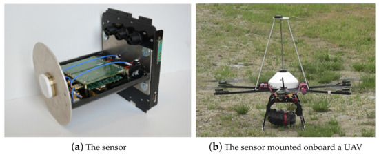
Figure 1.
The global navigation satellite systems (GNSS)-R sensor used in this study, and a picture from one of the data collection campaigns.
2.1. The GNSS-Reflectometry Sensor
In this section, the original version of the GNSS-Reflectometry sensor used for data collection is described, then the modifications introduced to achieve the low-complexity version are explained. The complete details of the sensor were published in [48], however it is presented briefly here for sake of clarity of the experimental setup and the post-processing methodology.
The original sensor was designed with the aim of detecting water surfaces and land water content. It is intended for small UAVs with weight of 3 kg and memory limit able to store 30 min of data collection. The sensor receives both direct and reflected GNSS signlas using three separate antennas: (1) an up-looking RHCP antenna, (2) a down-looking LHCP antenna and (3) a down-looking RHCP antenna.
The sensor features four synchronized RF channels connecting the direct signal and the LHCP reflected signal to a front end, while the RHCP reflected signal with the direct signal are connected to another front end. Both front-ends down convert the direct signals to baseband (BB), while the reflected signals are down converted to an intermediate frequency (IF) in sake of low noise levels for the already weak reflected signals. An embedded microprocessor controls the flow of the digital samples of all channels.
In this work, in order to reduce the total mass of the payload, a simplified version of the sensor that embeds (1) the RHCP antenna for the direct signal and (2) the LHCP antenna for the reflected ray, was used.
2.2. Data Collection Campaign
The data collection flights were over different types of water surfaces (rivers, lakes, ponds, etc.) selected to test the sensor in detecting well known water surfaces. Nevertheless, these data were considered valuable by this study to challenge the sensor in detecting flood-similar water presence. The criteria for water detection were defined as being able to detect small water surfaces, distinguish narrow water flows and estimating water surfaces area. With that in mind, three test cases were chosen from the data campaign area:
- A 0.89 km2 lake with a known basin where we could challenge the ability to estimate the area covered by water and its boundary.
- A river stream to challenge detecting narrow water streams.
- Small ponds of water to challenge the detection of small and unexpected water content on ground.
Being not flood events, we were able to overlap the GNSS-R measurements on available orthophotos without the need for field measurements or satellite images taken on the same dates and time of the test flights.
2.3. Post Processing Methodology
Figure 2 shows the block diagram of the post-processing steps. First, we processed the digital samples of the direct RHCP signal using a GNSS software receiver. Here we extracted the UAV trajectory. We also retrieved the list of satellites in view during the data collection campaign, as shown in the upper chain of Figure 2. Then, we calculated the lines of specular points on the ground for all the visible satellites for the whole flight duration, utilizing the receiver trajectory extracted in the previous step, and the known satellites positions, as shown in the middle chain of Figure 2. We calculated the specular points using the algorithms in [16,28].

Figure 2.
Block diagram of the post-processing steps.
We processed samples of the LHCP signal to measure the power reflected by the surfaces, as shown in the bottom chain of Figure 2. We estimated the reflected power for all the visible satellites, by evaluating the cross-ambiguity function (CAF) [54] over a reduced search space [55]. The CAF is generally computed and compared to a threshold to detect the presence of a GNSS satellite signal, and in our case the detection of a GNSS signal reflected by a ground surface. The CAF was evaluated over a set of Doppler-delay values that define the search space where the reflected signal was cross-correlated with a local replica of the code. Figure 3a shows an example of the CAF of a visible satellite using the direct signal, and Figure 3b shows the CAF for the same satellite at the same time using the reflected signal. It can be noticed that the direct signal as expected has a peak that is well separated from the noise floor, while the CAF associated to the reflected signal shows a weaker peak but it is still visible.
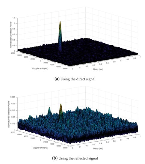
Figure 3.
Examples of the search space for a visible satellite when (a) evaluated from the direct signal, and (b) evaluated from the reflected signal.
We choose the peak-to-noise-floor separation [56] as a measure of the reflected signal strength:
where is the correlation peak value, and is the mean value of the correlation noise. was calculated from the peak values of the search space obtained cross-correlating the received signal with an orthogonal code not used by the constellation for the whole flight duration. The non-coherent integration time was fixed to 10 ms, and the coherent integration time was 1 ms i.e., we averaged 10 consecutive coherent integrations of 1 ms long. We evaluated the CAF at various rates: 1, 10 and 20 Hz, which corresponded to different levels of resolution along the lines of specular points. In this paper we are interested in understanding if this peak corresponds to reflection from a water surface. As will be shown later, when the signal is reflected from water, will generally be above the threshold we used to discriminate the presence of reflections.
2.4. The Data Sets
In this article, we processed two data sets collected during different flights, with different passes over the test area in different days and different seasons. The first flight was in December, 2013 and the second flight was in the following May. We processed both flight data using the same methodology, comparing the results for what concerns water detection on ground. In this section, we describe the data sets used.
Figure 4 shows the peak-to-noise-floor separation of data set (1) and data set (2), in dB, for a subset of the visible pseudo-random noise (PRN) codes. We computed at a rate of 20 Hz and we used a first order low pass digital Butterworth filter with a cutoff frequency of 1 Hz to smooth the measurements. The x-axis reports the time, in seconds, from the beginning of the data set. It can be noticed that has a time-variant trend. Focusing on data set (1), some epochs are characterized by values greater than 5 dB (e.g., 0–400 s), indicating potential signal reflections. Other epochs, such as those associated to PRN 32 in 600–820 s, have small values that hardly reach 2 dB. Variations can be observed among satellites, as noticeable for example between 900 s and 1200 s, where values related to PRN 32 are lower than the values associated to PRN 19 and 3. The same can be observed on the plot referencing to data set (2) which, however, had higher reflection values through out the whole flight duration.
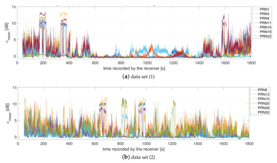
Figure 4.
Peak-to-noise-floor separation of the reflected signal for a subset of visible GPS satellites during (a) flight (1) December 2013 and (b) flight (2) May 2014.
In the next section, we reference each of these reflections to their ground reflecting points, with focus on reflections generated from water.
3. Results and Discussion
In this section we are going to present three case studies, that we have chosen to emphasise particular features and highlight the potential of UAV based GNSS-R for monitoring surface water. The first case describes detecting the Avigliana lakes which are two adjacent lakes in Northern Italy. We took them as reference for calibrating both the GNSS–R sensor and the post–processing algorithms. The other two cases relate to smaller and narrower water surfaces, where the performance of the technique is challenged in detecting unexpected water contents on ground and in recognizing narrow river streams.
3.1. Case-Study I: Lakes
The UAV flew over the Avigliana lakes, which are wide water bodies convenient for validating the sensor and the post–processing algorithms. The approximate dimensions of the largest lake is 970 m on the widest east–west direction, and 1200 m on the north–south direction. The sensor passed over the lakes three times: north–south, south–north, and west–east. The average height of the UAV was 450 m over the lake surface with average speed of 50 ms−1.
In data set (1) that originated Figure 4a, these passes correspond to epochs 170–230 s, 330–390 s and 1560–1620 s. Reflections were observed, as expected, during these epochs, as shown in Figure 5a, which is a zoom view into the epochs corresponding to the passes over the lakes. The figure shows that for some PRNs the values of increase up to roughly 10 dB and remain constant for many seconds. This trend can be noticed for the satellites that have specular points falling on the lakes and it confirms detecting GNSS signals reflected from the lakes. The periods of these reflections depend on the lake width, the sensor speed and the satellite-sensor geometry. Indeed, the value of stays high as long as the specular points are on water. It can be noticed also that the reflection value corresponding to water detection differs by some dBs for the different satellites. This is due to the different received power from the different satellites on the first place, which when reflected correspond to different surface properties. The same reflections can be noticed looking at data set (2) where the flight, again, passed over the lakes three times: north–south, south–north and west–east. The corresponding passes are 600–700 s, 800–860 s and 1190–1240 s as reported in Figure 4b and zoom-viewed in Figure 5b.
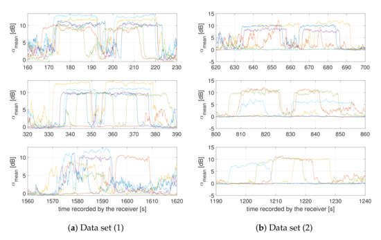
Figure 5.
Comparison of the peak-to-noise-floor separation of the reflected signal for (a) data set (1), and (b) data set (2), when the sensor crossed the lakes on the different passes: north to south (top), south to north (middle), and west to east (bottom).
This concept can be appreciated in Figure 6a,b, which show the specular points lines of all the PRNs in view, superimposed into orthophotomaps. These maps correspond to data set (1) and data set (2) respectively. The flight trajectory is represented by the black dots and it is displayed at a rate of 1Hz. The colored lines are the specular points of the satellites which showed enhanced values of . The colors of the specular points reflect on the values of associated to them. From Figure 6, it can be noticed that the boundary between land and water is clearly distinguishable and it correlates with the orthophotomap. Concentrating on the area between the two lakes, the steep increments and decays in the values of the peak-to-noise-floor separation along time, that were commented in Figure 5, actually correspond to the water–land boundaries. The resolution of the water edge detection is at the order of tens of meters, as expected and reported in similar investigations available in the scientific literature. This demonstrates the suitability of the GNSS-R onbaord UAVs in detecting water at a resolution space-borne GNSS-R are not able to provide at the moment. Note that we processed these measurements at 20 Hz rate, with an integration time of 10 ms only. The measurements rate could be set up to 100 Hz to provide an even higher resolution.
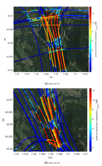
Figure 6.
GNSS signals specular reflection points superimposed into an orthophotomap. The colorgrades indicate the measured reflected power .
Now that we know which reflections were from the lake, we want to have an insight on the reflected power as a function of the satellite elevation. The reflected power depends on many factors: the transmitted power by the satellite, the satellite elevation, the receiving antenna pattern, the properties of the reflecting surface, among others. Figure 7 reports the elevation angle for the reflections observed over the lake. Each point is averaged from five consecutive seconds during which the specular points were falling on the lakes. We used samples from both data sets (1) and (2) to create this graph. We also reported the PRN associated to each of these data points. It can be noticed that the reflected power from water roughly increases linearly with the incident angle (the satellite elevation). It can also be noticed that although we did not set a cut-off for the elevation angle, the useful measurements i.e., the measurements from water, were for angles greater than 30 degrees in our data collection. Measurements from satellites with less then 30 simply did not fall on the lakes during this data collection, and thus did not show significant reflections.
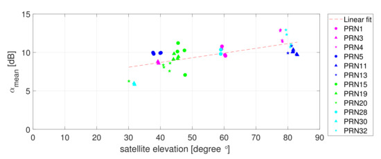
Figure 7.
The reflected power from the lake VS. satellite elevation.
The previous results and discussion prove the possibility of detecting the presence of water using our low cost, software radio GNSS-R sensor. They also prove that the edges of water are well detected. In the following sub-sections, we are investigating the collected data to extract information about the area of the detected water surfaces. Then, we are analyzing the benefit of multi-GNSS for GNSS-R, by investigating the improvement in water surface area estimation when multi-GNSS are considered.
Water Surface Area Estimation and Benefit of Multi-GNSS
Figure 8 reports the lines of specular points for which the value of exceeded 6 dB. Here, we superimposed the specular points into the orthophotomap of the upper lake and we linked the extreme points in order to form a polygon. This roughly creates an estimation of the water surface using GNSS-R. This particular encircled area is 0.822 km2. It is marginally smaller than the true surface of the lake which is approximately 0.89 km2 as reported in [57].
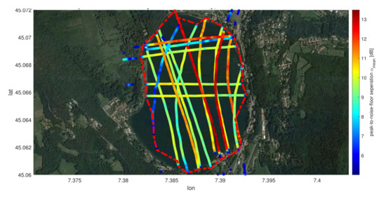
Figure 8.
Estimation of the Northern Avigliana lake surface area using GNSS-R. The red dotted lines represent the estimated boundary of the lake from the GNSS signals reflected from the water surface.
This estimate of the surface water area is about 7.5% less than the true area. But, since we are processing only the reflected GPS signals, the accuracy of such an estimate could be enhanced by taking advantage of multi-GNSS signals.
In order to investigate the improvement introduced by Galileo, GLONASS and BeiDou signals, we simulated a realistic flight trajectory and evaluated the increase in the number of specular points on the Northern lake. Figure 9a reports the sensor trajectory we choose for the simulation. It passes the Northern lake roughly in the middle, both on the north–south and west–east directions. We calculated the lines of specular points for the satellites belonging to the various constellations. We evaluated this trajectory at 100 and 200 m heights above the Earth surface, which are typical values for small UAV flights. The reason for simulating two heights is to ensure that the simulated height of the flight is not biasing the results we obtain, due to the fact that we are measuring a specific lake area; since the flight height should be proportional to the size of the targeted water body.
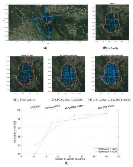
Figure 9.
Simulation results of multi-GNSS reflections: (a) the sensor trajectory considered, (b–e) the specular points lines using the different GNSS constellations, (f) the ratio between the estimated and the real area of the Northern Avigliana lake versus the number of satellites in view, two different heights of the sensor are considered.
Figure 9b–e show samples of the results, with clear enhancement in the number of specular points lines when constellations are added. Here we report the results of the 200 m flight height above the Northern lake only. The advantages of considering multi-GNSS reflectometry were also quantified in terms of the accuracy of the estimation of the surface area of the Northern lake, evaluated as the ratio between the estimated area and the true area. Figure 9f reports the estimation accuracy versus the number of visible satellites, which improves when adding more GNSS signals. It can be seen that the accuracy of the estimation using GPS only remains at about 80% for the two heights considered for the UAV, but increases to 90% when including Galileo. It further improves when GLONASS is added, and reaches 98% when Beidou is added. Notice that the curves for the different heights follow the same trend which supports our conclusion that the more satellites, the better the area estimation accuracy.
In fact, the high–end multi-constellation GNSS receivers, are already the state-of-the-art for the majority of the civil applications and their use on–board UAVs is growing. Indeed, the results presented in this sub–section refer to a particular case study (and thus they rely on the properties of this water body). Nevertheless, they demonstrate the expected advantages of processing reflected multi-GNSS signals. Processing multi-GNSS signals allows increasing the number of specular reflection points over a certain area. As an example, by, adding Galileo, we expect to double the number of visible satellites compared to what we could have if we were using GPS alone. At mid latitudes, the number of visible satellites can be greater than 40 when GLONASS and Beidou are considered too. This results in increasing the number of polygon vertices and therefore creates a more accurate estimation of the water surfaces.
Undoubtedly, the method presented here is an effective and simple way for estimating surface water. It can be integrated with other sources of data, or even to be used when orthophotos or maps are not available. Surely any reduction or expansion in the water surface can be detected when comparing against historic data. Indeed, utilizing UAV-based GNSS-R sensors, combined with ad hoc processing routines, proves to be an innovative tool for water monitoring. The results shown here were obtained computing the specular points at a rate of 20 Hz, but finer resolutions are attainable with a moderate increase in the complexity.
3.2. Case-Study II: River Stretches
The second case study presents detecting and measuring the Dora river stretches, which have widths that vary between few meters and tens of meters.
The values of for PRN 1 and PRN 32 from data set (1) are reported in Figure 10a, for one pass crossing the river course. These PRNs have been selected because they show an evident increment of in the observed time window. Using the same approach followed for the previous case study, we superimpose the lines of specular points to an orthophotomap in Figure 10b. Again, the black points show the flight trajectory displayed at a rate of 1 Hz. The colored lines are the specular points displayed with a rate of 20 Hz. The values of associated to these specular points are indicated by the colors of the lines. The reflected signals recorded from the river can be appreciated from Figure 10b, where the boundaries between land and water correlate well with the orthophotomap, particularly the reflections from the specular points associated to PRN1 (see the left part of Figure 10b). The width of the river where the specular points are red is approximately 30 m. However, differences in the reflected power can be noticed by observing values for different satellites. Here, the values of for PRN32 are lower compared the values associated to PRN1. This is reasonably due to the different features of the reflecting surface. While for PRN1 the line of specular points crosses a portion of the river with sharp transitions between land and water, the same ways as in case study 1 (i.e., the red portion in the figure), the line of specular points related to PRN32 falls on a portion of the river following an artificial dam. Here, the water depth is low, withHere the roughness of the water is different than the other section of the river crossed by PRN1 mentioned above, with low water depth and stones outcropping on the river level.
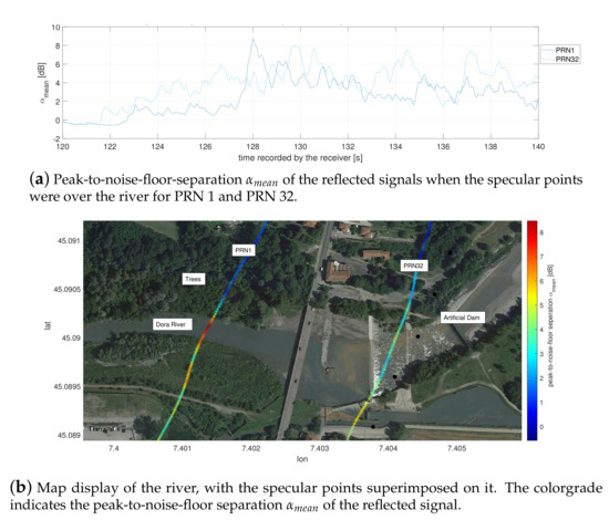
Figure 10.
Example of river width detection taken from data set (1).
Figure 11 reports the reflections from another portion of the river. These were measured from data set (2). The width of this water channel is approximately 12 m. The sensor and the post-processing methodology are the same, so is the result (i.e., water channel detection): boundaries of the river stretch can be detected, and its width eventually estimated.
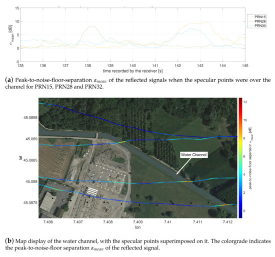
Figure 11.
Example of water channel width detection taken from data set (2).
3.3. Case-Study III: Small Artificial Water Basins
The third case study presents the detection of the presence of small water surfaces, a small lake in the backyard of building and two small adjacent artificial ponds in a golf court. Starting with the golf court water basins, Figure 12a shows the presence of reflected signals, in terms of peak-to-noise-floor separation for PRN 11 and PRN 32. These showed an increment of the values that could be associated to reflections. Following the same approach used for the previous case studies, the specular points lines were overlapped to the orthophotomap. Figure 12b shows that the edges of the pond approximately correspond to the increase (decrease) of the peak-to-noise-floor separation. The width of the upper pond is approximately 120 m while the smaller pond is approximately 35 m. This indicates that GNSS-R, in addition to the monitoring of lakes and rivers, can enable the detection of small water surfaces.
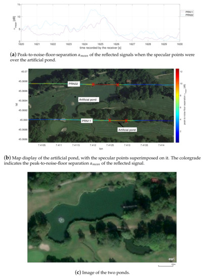
Figure 12.
Example of the detection of an artificial pond taken from data set (1).
The reflections from the small backyard lake of Figure 13 were recorded on flight (2). The approximate width of this lake is 45 m. Like in the case of the golf court basin, the presence of the pond was clearly detected and the width of the lake is clearly distinguishable processing PRN13. These types of detection can provide valuable data to the potential application of supporting operations performed after floods, especially for post-mission analysis and in case images from satellites are not available.
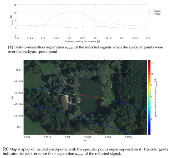
Figure 13.
Example of the detection of an backyard pond taken from data set (2).
4. Conclusions
This paper presents the preliminary results of investigating the feasibility of using data from UAV-based GNSS-R sensors for water detection and with a potential application in supporting flood monitoring operations. The GNSS-R sensor used in this paper is a custom made sensor, built using low cost commercial of the shelf components. It allowed for collecting samples of ground-reflected GNSS signals, which revealed the presence of water surfaces on ground when post processed.
Three different case studies were investigated through the processing of two different data sets collected in different seasons. The case studies are: a lake, a river and artificial water basins. These cases were selected because they challenged the sensor in detecting flood-like water presence. Performing the data collections over the lakes (and in general over large water surfaces), we were able to detect the boundaries between ground and water with few tens of meters accuracy and to estimate the extension of the water surface. Moreover, It was shown that the multi-GNSS approach (i.e.: processing of GPS, Galileo, GLONASS and Beidou signals) could even improve the estimation accuracy, without extra costs on the sensor hardware, but at the expenses of a moderate increase in the complexity of the software used in the off-line analysis. The data collections from the UAV based GNSS-R and the consequent signal processing demonstrated to be effective also for the detection of narrower water surfaces, like river stretches and water channels. In addition to that, small unexpected water presence on the ground were localized including an artificial pond in a golf court and a backyard pond. The experiments reported in this paper confirmed that the use of GNSS-R onboard UAVs is a valid remote sensing tool to be used for water detection, and potentially for flood monitoring operations. However, to extend these results to flood monitoring, weather conditions affecting both the UAV operations and the water surface roughness need to be further analyzed. The UAV stability, attitude and orientation are to be considered because the geo-referencing of the measurements is affected when the RHCP and the LHCP antennas might be no longer pointing at Zenith and Nadir respectively. Moreover, investigation of the roughness and wind speed from small and narrow water bodies could be of interest, in a similar way as GNSS-R has been used for ocean surface roughness and wind speed measurements e.g., in [18,19,21,22]. Furthermore, since flight trajectory optimization is a common practice in UAV-based data collections, we recommend investigating how GNSS-R measurements will perform in an optimized data collection scenario. Also investigating the optimization of the UAV trajectory and the data collection time of the day to achieve optimum multi-GNSS reflectometry measurements is suggested. Finally, for flood detection in the future, we recommend also investigating the possibility to integrate data from the digital elevation model of the terrain with data coming from GNSS-R sensors. Indeed, GNSS-R should be considered as a valuable source of geospatial data after floods, for UAV-based reconnaissance of remote areas and for environmental monitoring.
Author Contributions
Conceptualization, M.P., F.D. (Fabio Dovis) and F.D. (Fabrizio Dominici); methodology, R.I. and M.P.; software, R.I.; validation, M.P. and F.D. (Fabio Dovis); formal analysis, R.I. and M.P.; investigation, G.M.; resources, G.M.; data curation, R.I.; writing—original draft preparation, R.I., M.P. and G.M.; writing—review and editing, F.D. (Fabio Dovis); visualization, R.I.; supervision, F.D. (Fabio Dovis). All authors have read and agreed to the published version of the manuscript.
Funding
This research received no external funding.
Conflicts of Interest
The authors declare no conflict of interest.
References
- Schumann, G.J.P. Remote Sensing of Floods; Oxford University Press: Oxford, UK, 2017. [Google Scholar]
- Schumann, G.P.; Moller, D. Microwave remote sensing of flood inundation. Phys. Chem. Earth 2015, 83–84, 84–95. [Google Scholar] [CrossRef]
- Rahman, M.; Di, L. The state of the art of spaceborne remote sensing in flood management. Nat. Hazards 2017, 85, 1223–1248. [Google Scholar] [CrossRef]
- Cao, H.; Zhang, H.; Wang, C.; Zhang, B. Operational flood detection using Sentinel-1 SAR data over large areas. Water 2019, 11, 786. [Google Scholar] [CrossRef]
- Guo, M.; Li, J.; Sheng, C.; Xu, J.; Wu, L. A review of wetland remote sensing. Sensors 2017, 17, 777. [Google Scholar] [CrossRef] [PubMed]
- Lin, Y.; Yun, S.H.; Bhardwaj, A.; Hill, E. Urban flood detection with Sentinel-1Multi-Temporal Synthetic Aperture Radar (SAR) observations in a Bayesian framework: A case study for Hurricane Matthew. Remote Sens. 2019, 11, 1778. [Google Scholar] [CrossRef]
- Shen, X.; Wang, D.; Mao, K.; Anagnostou, E.; Hong, Y. Inundation extent mapping by synthetic aperture radar: A review. Remote Sens. 2019, 11, 879. [Google Scholar] [CrossRef]
- Kugler, Z.; Nghiem, S.; Brakenridge, G. L-band passive microwave data from SMOS for river gauging observations in tropical climates. Remote Sens. 2019, 11, 835. [Google Scholar] [CrossRef]
- Chew, C.; Reager, J.; Small, E. CYGNSS data map flood inundation during the 2017 Atlantic hurricane season. Sci. Rep. 2018, 8, 9336. [Google Scholar] [CrossRef]
- Alsdorf, D.; Rodríguez, E.; Lettenmaier, D. Measuring surface water from space. Rev. Geophys. 2007, 45. [Google Scholar] [CrossRef]
- Benoudjit, A.; Guida, R. A novel fully automated mapping of the flood extent on sar images using a supervised classifier. Remote Sens. 2019, 11, 779. [Google Scholar] [CrossRef]
- Lacava, T.; Cuomo, V.; Di Leo, E.; Pergola, N.; Romano, F.; Tramutoli, V. Improving soil wetness variations monitoring from passive microwave satellite data: The case of April 2000 Hungary flood. Remote Sens. Environ. 2005, 96, 135–148. [Google Scholar] [CrossRef]
- Refice, A.; Capolongo, D.; Pasquariello, G.; Daaddabbo, A.; Bovenga, F.; Nutricato, R.; Lovergine, F.; Pietranera, L. SAR and InSAR for flood monitoring: Examples with COSMO-SkyMed data. IEEE J. Sel. Top. Appl. Earth Obs. Remote Sens. 2014, 7, 2711–2722. [Google Scholar] [CrossRef]
- Faruolo, M.; Coviello, I.; Lacava, T.; Pergola, N.; Tramutoli, V. A multi-sensor exportable approach for automatic flooded areas detection and monitoring by a composite satellite constellation. IEEE Trans. Geosci. Remote Sens. 2013, 51, 2136–2149. [Google Scholar] [CrossRef]
- Mason, D.; Horritt, M.; Dall’Amico, J.; Scott, T.; Bates, P. Improving river flood extent delineation from synthetic aperture radar using airborne laser altimetry. IEEE Trans. Geosci. Remote Sens. 2007, 45, 3932–3943. [Google Scholar] [CrossRef]
- Gebre-Egziabher, D.; Gleason, S. GNSS Applications and Methods; Artech House: London, UK, 2009. [Google Scholar]
- Nghiem, S.; Zuffada, C.; Shah, R.; Chew, C.; Lowe, S.; Mannucci, A.; Cardellach, E.; Brakenridge, G.; Geller, G.; Rosenqvist, A. Wetland monitoring with global navigation satellite system reflectometry. Earth Space Sci. 2017, 4, 16–39. [Google Scholar] [CrossRef] [PubMed]
- Garrison, J.; Katzberg, S.; Hill, M. Effect of sea roughness on bistatically scattered range coded signals from the Global Positioning System. Geophys. Res. Lett. 1998, 25, 2257–2260. [Google Scholar] [CrossRef]
- Clarizia, M.P.; Ruf, C.S.; Jales, P.; Gommenginger, C. Spaceborne GNSS-R Minimum Variance Wind Speed Estimator. IEEE Trans. Geosci. Remote Sens. 2014, 52, 6829–6843. [Google Scholar] [CrossRef]
- Beckheinrich, J.; Beyerle, G.; Schoen, S.; Apel, H.; Semmling, M.; Wickert, J. WISDOM: GNSS-R based flood monitoring. In Proceedings of the GNSS+R 2012 Workshop on Reflectometry Using GNSS and Other Signals of Opportunity, West Lafayette, IN, USA, 10–11 October 2012. [Google Scholar] [CrossRef]
- Esterhuizen, S.; Masters, D.; Akos, D.; Vinande, E. Experimental characterization of land-reflected GPS signals. In Proceedings of the 18th International Technical Meeting of the Satellite Division of The Institute of Navigation (ION GNSS 2005), Long Beach, CA, USA, 13–16 September 2005; pp. 1670–1678. [Google Scholar]
- Kainulainen, J.; Salo, S.; Lahtinen, J.; Calves, G.M.; Seppanen, J.; Praks, J.; Hakala, T.; Chen, Y.; Hyyppa, J.; Unwin, M.; et al. Airborne Wind Vector Scatterometer for Sea Surface Measurements. IEEE J. Sel. Top. Appl. Earth Obs. Remote Sens. 2019, 12, 2470–2476. [Google Scholar] [CrossRef]
- Pei, Y.; Notarpietro, R.; Savi, P.; Cucca, M.; Dovis, F. A fully software Global Navigation Satellite System reflectometry (GNSS-R) receiver for soil monitoring. Int. J. Remote Sens. 2014, 35, 2378–2391. [Google Scholar] [CrossRef]
- Pei, Y.; Notarpietro, R.; De Mattia, S.; Savi, P.; Dovis, F.; Pini, M. Remote sensing of soil based on a compact and fully software GNSS-R receiver. In Proceedings of the 26th International Technical Meeting of the Satellite Division of the Institute of Navigation (ION GNSS 2013), Nashville, TN, USA, 16–20 September 2013; Volume 1, pp. 56–61. [Google Scholar]
- Masters, D. Surface Remote Sensing Applications of GNSS Bistatic Radar: Soil Moisture and Aircraft Altimetry. Ph.D. Thesis, University of Colorado, Denver, CO, USA, 2004. [Google Scholar]
- Masters, D.; Katzberg, S.; Axelrad, P. Airborne GPS Bistatic Radar Soil Moisture Measurements During SMEX02. In Proceedings of the International Geoscience and Remote Sensing Symposium (IGARSS), Toulouse, France, 21–25 July 2003; Volume 2, pp. 896–898. [Google Scholar]
- Shen, L.C.; Juang, J.C.; Tsai, C.L.; Chang, C.C.; Ko, P.Y.; Tseng, C.L. Stream soil moisture estimation by reflected GPS signals with ground truth measurements. IEEE Trans. Instrum. Meas. 2009, 58, 730–737. [Google Scholar] [CrossRef]
- Helm, A. Ground-based GPS Altimetry with the L1 OpenGPS Receiver Using Carrier Phase-Delay Observations of Reflected GPS Signals; Technical Report STR 08/10; Deutsches GeoForschungsZentrum GFZ: Berlin, Germany, 2008. [Google Scholar]
- Vinande, E.; Akos, D.; Masters, D.; Axelrad, P.; Esterhuizen, S. GPS bistatic radar measurements of aircraft altitude and ground objects with a software receiver. In Proceedings of the 61st Annual Meeting of the Institute of Navigation, Cambridge, MA, USA, 27–29 June 2005; pp. 528–534. [Google Scholar]
- Small, E.; Larson, K.; Braun, J. Sensing vegetation growth with reflected GPS signals. Geophys. Res. Lett. 2010, 37. [Google Scholar] [CrossRef]
- Zribi, M.; Motte, E.; Baghdadi, N.; Baup, F.; Dayau, S.; Fanise, P.; Guyon, D.; Huc, M.; Wigneron, J.P. Potential Applications of GNSS-R Observations over Agricultural Areas: Results from the GLORI Airborne Campaign. Remote Sens. 2018, 10, 1245. [Google Scholar] [CrossRef]
- Rodriguez-Alvarez, N.; Aguasca, A.; Valencia, E.; Bosch-Lluis, X.; Camps, A.; Ramos-Perez, I.; Park, H.; Vall-Llossera, M. Snow thickness monitoring using GNSS measurements. IEEE Geosci. Remote Sens. Lett. 2012, 9, 1109–1113. [Google Scholar] [CrossRef]
- Unwin, M.; Gleason, S.; Brennan, M. The Space GPS Reflectometry Experiment On the UK Disaster Monitoring Constellation Satellite. In Proceedings of the 16th International Technical Meeting of the Satellite Division of the Institute of Navigation (ION GPS/GNSS 2003), Portland, OR, USA, 9–12 September 2003; pp. 2656–2663. [Google Scholar]
- Ruf, C.; Unwin, M.; Dickinson, J.; Rose, R.; Rose, D.; Vincent, M.; Lyons, A. CYGNSS: Enabling the Future of Hurricane Prediction [Remote Sensing Satellites]. IEEE Geosci. Remote Sens. Mag. 2013, 1, 52–67. [Google Scholar] [CrossRef]
- Wickert, J.; Cardellach, E.; Martín-Neira, M.; Bandeiras, J.; Bertino, L.; Andersen, O.B.; Camps, A.; Catarino, N.; Chapron, B.; Fabra, F.; et al. GEROS-ISS: GNSS REflectometry, Radio Occultation, and Scatterometry Onboard the International Space Station. IEEE J. Sel. Top. Appl. Earth Obs. Remote Sens. 2016, 9, 4552–4581. [Google Scholar] [CrossRef]
- Foti, G.; Gommenginger, C.; Jales, P.; Unwin, M.; Shaw, A.; Robertson, C.; Roselló, J. Spaceborne GNSS reflectometry for ocean winds: First results from the UK TechDemoSat-1 mission. Geophys. Res. Lett. 2015, 42, 5435–5441. [Google Scholar] [CrossRef]
- Li, W.; Cardellach, E.; Fabra, F.; Ribó, S.; Rius, A. Lake Level and Surface Topography Measured With Spaceborne GNSS-Reflectometry From CYGNSS Mission: Example for the Lake Qinghai. Geophys. Res. Lett. 2018, 45, 13332–13341. [Google Scholar] [CrossRef]
- Carreno-Luengo, H.; Lowe, S.; Zuffada, C.; Esterhuizen, S.; Oveisgharan, S. Spaceborne GNSS-R from the SMAP Mission: First Assessment of Polarimetric Scatterometry over Land and Cryosphere. Remote Sens. 2017, 9. [Google Scholar] [CrossRef]
- Clarizia, M.P.; Pierdicca, N.; Costantini, F.; Floury, N. Analysis of CYGNSS Data for Soil Moisture Retrieval. IEEE J. Sel. Top. Appl. Earth Obs. Remote Sens. 2019, 12, 2227–2235. [Google Scholar] [CrossRef]
- Al-Khaldi, M.M.; Johnson, J.T.; O’Brien, A.J.; Balenzano, A.; Mattia, F. Time-Series Retrieval of Soil Moisture Using CYGNSS. IEEE Trans. Geosci. Remote Sens. 2019, 57, 4322–4331. [Google Scholar] [CrossRef]
- Whitehead, K.; Hugenholtz, C.H. Remote sensing of the environment with small unmanned aircraft systems (UASs), part 1: A review of progress and challenges. J. Unmanned Veh. Syst. 2014, 2, 69–85. [Google Scholar] [CrossRef]
- Whitehead, K.; Hugenholtz, C.H.; Myshak, S.; Brown, O.; LeClair, A.; Tamminga, A.; Barchyn, T.E.; Moorman, B.; Eaton, B. Remote sensing of the environment with small unmanned aircraft systems (UASs), part 2: Scientific and commercial applications. J. Unmanned Veh. Syst. 2014, 02, 86–102. [Google Scholar] [CrossRef]
- Tamminga, A.; Eaton, B.; Hugenholtz, C. UAS-based remote sensing of fluvial change following an extreme flood event. Earth Surf. Process. Landf. 2015, 40, 1464–1476. [Google Scholar] [CrossRef]
- Feng, Q.; Liu, J.; Gong, J. Urban flood mapping based on unmanned aerial vehicle remote sensing and random forest classifier—A case of yuyao, China. Water 2015, 7, 1437–1455. [Google Scholar] [CrossRef]
- Colomina, I.; Molina, P. Unmanned aerial systems for photogrammetry and remote sensing: A review. ISPRS J. Photogramm. Remote Sens. 2014, 92, 79–97. [Google Scholar] [CrossRef]
- Rosen, P.; Hensley, S.; Wheeler, K.; Sadowy, G.; Miller, T.; Shaffer, S.; Muellerschoen, R.; Jones, C.; Zebker, H.; Madsen, S. Uavsar: A new NASA airborne SAR system for science and technology research. In Proceedings of the IEEE National Radar Conference, Verona, NY, USA, 24–27 April 2006; pp. 22–29. [Google Scholar] [CrossRef]
- Rosen, P.; Heasley, S.; Wheeler, K.; Sadowy, G.; Miller, T.; Shaffer, S.; Muellerschoen, R.; Jones, C.; Madsen, S.; Zebker, H. UAVSAR: New NASA airborne SAR system for research. IEEE Aerosp. Electron. Syst. Mag. 2007, 22, 21–28. [Google Scholar] [CrossRef]
- Troglia Gamba, M.; Marucco, G.; Pini, M.; Ugazio, S.; Falletti, E.; Lo Presti, L. Prototyping a GNSS-Based Passive Radar for UAVs: An Instrument to Classify the Water Content Feature of Lands. Sensors 2015, 15, 28287–28313. [Google Scholar] [CrossRef]
- Esterhuizen, S.; Akos, D. The Design, Construction, and Testing of a Modular GPS Bistatic Radar Software Receiver for Small Platforms. Master’s Thesis, University of Colorado, Denver, CO, USA, 2006. [Google Scholar]
- Junered, M.; Esterhuizen, S.; Akos, D.; Axelrad, P. A Modular GPS Remote Sensing Software Receiver for Small Platforms. In Proceedings of the 19th International Technical Meeting of the Satellite Division of The Institute of Navigation (ION GNSS 2006), Fort Worth, TX, USA, 26–29 September 2006; pp. 634–642. [Google Scholar]
- Marchan-Hernandez, J.; Camps, A.; Rodriguez-Alvarez, N.; Bosch-Lluis, X.; Ramos-Perez, I.; Valencia, E. PAU/GNSS-R: Implementation, performance and first results of a real-time delay-doppler map reflectometer using global navigation satellite system signals. Sensors 2008, 8, 3005–3019. [Google Scholar] [CrossRef]
- I-REACT Project. Available online: http://www.i-react.eu/ (accessed on 14 June 2019).
- Imam, R.; Pini, M.; Marucco, G.; Dominici, F.; Dovis, F. Data from GNSS-based passive radar to support flood monitoring operations. In Proceedings of the 2019 9th International Conference on Localization and GNSS (ICL-GNSS), Nuremberg, Germany, 4–6 June 2019. [Google Scholar]
- Lo Presti, L.; Fantino, M.; Pini, M. Digital Signal Processing for GNSS Receivers. In Handbook of Position Location; John Wiley & Sons, Ltd.: Hoboken, NJ, USA, 2019; Chapter 21; pp. 707–761. [Google Scholar] [CrossRef]
- Linty, N.; Dovis, F. An overview on Global Positioning Techniques for Harsh Environments. In Handbook of Position Location; John Wiley & Sons, Ltd.: Hoboken, NJ, USA, 2019; Chapter 23; pp. 839–881. [Google Scholar] [CrossRef]
- Dovis, F. GNSS Interference Threats and Countermeasures; Artech House: London, UK, 2015. [Google Scholar]
- Borasi, L.; Maffiotti, A. Alpine Lakes: Survey on Climate Change; Arpa Piemonte: Torino, Italy, 2012. [Google Scholar]
© 2019 by the authors. Licensee MDPI, Basel, Switzerland. This article is an open access article distributed under the terms and conditions of the Creative Commons Attribution (CC BY) license (http://creativecommons.org/licenses/by/4.0/).