Abstract
In mobile devices, the screen size limits conveyance of immersive experiences; haptic feedback coupled with visual feedback is expected to have a better effect to maximize the level of immersion. Therefore, this paper presents a miniature tunable haptic stylus based on magnetorheological (MR) fluids to provide kinesthetic information to users. The designed stylus has a force generation, force transmission, and housing part; moreover, in the stylus, all three operating modes of MR fluids contribute to the haptic actuation to produce a wide range of resistive force generated by MR fluids in a limited size, thereby providing a variety of pressing sensations to users. A universal testing machine was constructed to evaluate haptic performance of the proposed haptic stylus, whose resistive force was measured with the constructed setup as a function of pressed depth and input current, and by varying the pressed depth and pressing speed. Under maximum input voltage, the stylus generates a wide range of resistive force from 2.33 N to 27.47 N, whereas under maximum pressed depth it varied from 1.08 N to 27.47 N with a corresponding change in voltage input from 0 V to 3.3 V. Therefore, the proposed haptic stylus can create varied haptic sensations.
1. Introduction
Because of advancements in mobile hardware technology, interaction with mobile virtual objects has become increasingly popular with most users owning a smart phone. Mobile virtual reality includes a variety of graphical content from a simple static object to one having complex dynamic behavior. A user who manipulates and interacts with these objects wants to haptically ”feel” not only the presence of objects but also their material properties. As the demand for realistic interaction with virtual objects increases, the importance of haptic technology also increases to ensure that the ultimate level of immersion is conveyed to users.
Haptic sensation consists of kinesthetic and tactile feelings. A kinesthetic feeling refers to sensory data obtained through receptors of joints, muscles, ligaments, etc. The tactile feeling is a cutaneous sensation obtained from receptors of the skin. A user recognizes the stiffness of an object through kinesthetic information and discerns the texture of an object through tactile information. Thus, to convey a more realistic haptic sensation to users in a virtual environment, both tactile and kinesthetic information should be simultaneously presented to users.
Recently, many mobile devices have used styluses to help users tap on the screen and allow them to delicately manipulate virtual contents. In virtual reality, while visual information is the most dominant sensory input for perceiving virtual objects, haptic information coupled with visual information increases the sense of reality. Therefore, many researchers have focused on tactile modules that stimulate the skin of users [1,2,3,4,5,6,7]. Lee et al., developed a haptic pen using a touch sensor and solenoid coil to create a sense of contact with virtual objects [1]. Kyung and Park presented a pen-like haptic interface, which consists of a compact pin-array tactile module and a vibrating module (Ubi-Pen), and verified its haptic performance [2,3]. Liao et al., developed a pen-type haptic interface device and evaluated its usefulness [4]. Cho et al., presented a haptic stylus to generate auditory-tactile feedback that provides realism in handwriting or drawing tasks [5]. Wang et al., suggested an electro-vibration based haptic pen which can create continuous tactile feedback [6]. Arasan et al., developed a vibrotactile pen for generating two haptic effects (static and dynamic vibration) and conveying them to users [7]. Although these pens can haptically simulate the roughness of a target object and can emulate button sensation using vibration, it is not easy to represent the stiffness of the virtual object through tactile feedback.
Many researchers have shown interest in incorporating kinesthetic effects in haptic styluses. Kamuro et al., suggested a pen-type hand held haptic interface conveying kinesthetic feeling to users [8]. Tian et al., proposed a haptic stylus which creates kinesthetic and tactile sensations [9]. Kianzad and MacLean developed a magic pen that generates kinesthetic sensation using a ball-point drive mechanism [10]. Kara and Patoglu suggested a haptic stylus having variable tip compliance [11]. Even though these haptic styluses directly provide kinesthetic information (for example, force or distributed pressure), actuation mechanisms are too bulky and heavy to be inserted into tiny styluses.
Therefore, the magnetorheological fluid (MR fluid), whose mechanical properties can be changed according to an external magnetic field, has been studied as a material for pen-type haptic devices to convey kinesthetic sensation to users [12,13]. MR fluids based haptic pen was developed to interact with an image on a mobile terminal [12]. Another haptic pen for creating kinesthetic sensation using a hybrid actuator (MR actuator with a voice coil motor) was introduced [13]. They used two modes (a flow mode and a shear mode) of the available three operating modes of MR fluids to increase haptic resistive force. Although their research works greatly help users to understand the material property of virtual objects by using kinesthetic information, the range of haptic force can be further expanded if the squeeze mode is added to the haptic pen. The reason being that squeeze mode has the greatest effect on the generation of resistive force among these three operating modes in MR fluids [14,15,16,17,18]. In this paper, we propose a new design of tiny haptic stylus, in which all three modes (a shear mode, flow mode, and squeeze mode) of MR fluids can contribute to the haptic actuation, to increase the magnitude of haptic force to the level where users are truly “satisfied” in a small size. The proposed tiny haptic stylus is expected to be useful for interaction with virtual objects because of its simple structure and haptic performance.
2. Design of A New Kinesthetic Stylus
2.1. Overall Structure
Figure 1 shows the structure of a proposed haptic stylus which consists of three parts: (1) force generation, (2) force transmission, and (3) a housing part. The force generation part, which plays a role in creating resistive force, includes a T-shape rod, a spring, an O-ring, a bottom plate, a spacer, a plunger, a solenoid coil, a magnetic shelter, and a top plate. The force transmission part is composed of a pen tip and hollow shaft. The spring is used to restore the compressed force generation part to its initial position and the T-shaped rod transmits the resistance force from the force generation part to the force transmission part. One end of the T-shaped rod is connected to the hollow shaft, and the other end of the T-shaped rod is inserted into the hole of the bottom plate with a spring. The hollow shaft acts as the central axis of the vertical movement of the proposed module. The housing part consists of an upper and a lower housing. The upper housing is designed to minimize magnetic flux leakage when voltage input is applied to the solenoid. The force generation part is inserted into the upper housing. The T-shaped rod is connected to one end of the hollow shaft, and the pen tip is inserted into the other end of the hollow shaft. The lower housing covers the force transmission part and is then inserted into the upper housing.
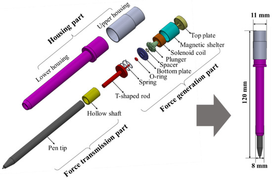
Figure 1.
Schematic of the proposed kinesthetic stylus.
2.2. Operating Principle
The key components of the proposed haptic stylus are MR fluid (MRF) and the solenoid. The MR fluid is filled in the magnetic shelter that includes the solenoid. The solenoid coil creates magnetic fields to control the stiffness of MR fluids. The magnetic shelter provides a path along which the magnetic field induced by the solenoid coil flows. Figure 2 shows the operating principle of the proposed haptic stylus. When there is no voltage in the solenoid, the MRF is in the fluid state. Therefore, when a user holds the proposed haptic stylus and pushes the screen of a mobile device with the pen tip, the haptic stylus is softly pressed, and the user can feel the softness. If an input voltage is applied to the solenoid coil in the proposed module, the magnetic particles in the MRF form chains and the MRF becomes semisolid. During this change, since the solidification extent is proportional to the applied magnetic field, the force generation part in the haptic stylus can create various haptic sensations. Therefore, when a user interacts with mobile virtual contents using the haptic stylus, he/she can sense a variety of haptic sensations.
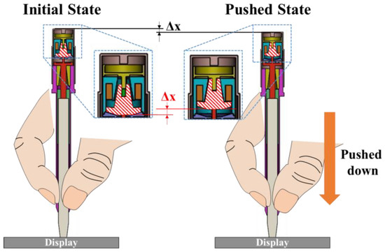
Figure 2.
Operating principle of the proposed haptic stylus.
2.3. Optimization of the Haptic Stylus
For maximizing the haptic performance of the proposed stylus, we need to not only optimize the solenoid and the gap distance between magnetic shelter and the plunger but also reduce the friction between the plunger and the top plate. First, we optimize the diameter of the solenoid coil to maximize resistive force with less power consumption. We simulated the solenoid coil assuming that this module consumes a power of 0.6 W under an input voltage of 3.3 V. The resistive force of the proposed haptic stylus is highly related to the magneto-motive force of the solenoid coil. The magneto-motive force (F) of the solenoid coil and the power consumption are expressed by Equation (1) [19]:
In Equation (1), N is the number of turns of the solenoid coil, V is the input voltage, A is the area of pure conductor, ρ is the resistivity of copper (1.72 × 10⁻⁸ Ωm), and lt is the total length of the solenoid coil. Because we used a multilayer solenoid coil in the proposed haptic stylus, the area (A) of pure conductor and total length (lt) of the copper wire are expressed by Equations (2) and (3), respectively.
In Equations (2) and (3), π is the ratio of a circle’s circumference to its diameter, dw is a diameter of the wire of the solenoid coil, and rm is the average radius of the solenoid coil.
The power consumption (P) of the solenoid coil is calculated by the following Equation:
Figure 3 shows the simulation result of the magneto-motive force (MMF) of the solenoid coil according to its wire diameter. The black line is the computed magneto-motive force by varying the wire diameter, and the red line is the magneto-motive force with a fixed power consumption of 0.6 W. From the result, the wire diameter of the solenoid coil was selected as 0.11 mm.
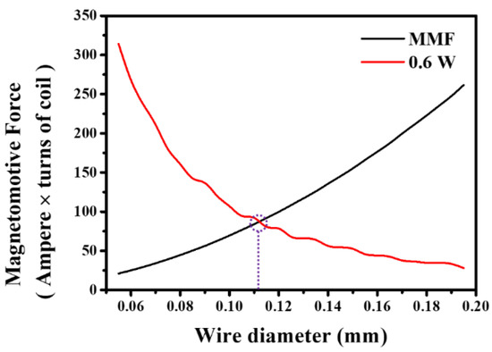
Figure 3.
Simulation result of the solenoid coil: magneto-motive force vs. wire diameter.
As mentioned earlier, there are three operating modes in MRF: (1) a flow mode (MR fluids flow due to a pressure gradient between the two stationary plates), (2) a shear mode (MR fluids flow between two plates that are moving relative to one another), and (3) a squeeze mode (MR fluids flow between the two plates that are moving in a direction that is perpendicular to their planes) [14,15,16,17,18]. To maximize the resistive force in a small device, the proposed haptic stylus should be fabricated in a structure in which all three operation modes of MR fluids can contribute to the actuation. To do this, an FEM simulation was conducted using a commercialized software (Maxwell 2D v14, Ansoft, Pennsylvania, USA). Figure 4 shows the cross-sectional view of the assembled force generation part and its flux path simulation result. The solenoid coil is attached and fixed to the inside of the magnetic shelter. When the T-shaped rod is pressed, this pressing force causes the plunger to move upward. At this time, the magnitude of the resistive force can be controlled by changing the state of MR fluid. From the results (Figure 4), we found that the magnetic flux flows well without magnetic saturation or leakage in the proposed design. As the plunger moves down, the distance between itself and the declined plane of the magnetic shelter becomes closer and the MR fluid is pressed (squeeze mode). The squeezed MR fluid flows through the gap between the plunger and the magnetic shelter (flow mode). Meanwhile, the movement of the plunger causes relative motion between the two slopes (the plunger and the magnetic shelter) and this relative motion creates shear stress (shear mode). Thus, we found that the proposed haptic stylus is designed to use all three operating modes of the MR fluids so that it can generate sufficient resistive force in a small size.
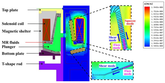
Figure 4.
Cross-sectional view of the force generating part and its simulation result.
The gap distance between the magnetic shelter and the plunger is another important factor to maximize the haptic performance because the gap is filled with MR fluid. Thus, we simulated the resistive force (haptic performance) by varying the distance (y) between the magnetic shelter and the plunger (Figure 5). The distance (y) was varied from 1.3 mm to 1.8 mm at an interval of 0.1 mm. As shown in Figure 5, the result indicates that the resistive force decreases as the distance (y) increases. Therefore, it is better to decrease the distance between the magnetic shelter and the plunger. However, in the case of a distance of 1.3 mm, the normal distance between the magnetic shelter and the plunger when the haptic stylus is fully pressed (d = 1 mm) is too close () considering the manufacturing error. Therefore, in this study, we selected the distance as 1.4 mm.
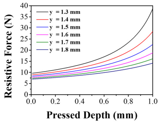
Figure 5.
Simulation result of the resistive force of the haptic stylus by varying the distance between the magnetic shelter and the plunger.
To reduce the initial resistive force (when there is no current), we simplified the top plate as shown in Figure 6. Due to this simple design of the top plate, we could increase the area where the magnetic flux flows, resulting in the improvement of the haptic resistive force.
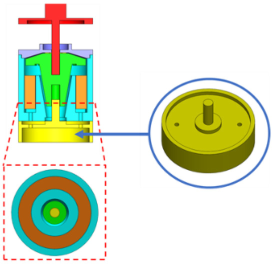
Figure 6.
The simple design of the top plate.
2.4. Fabrication of the Tiny Haptic Stylus
Figure 7 shows the constructed haptic stylus consisting of the lower housing, upper housing, hollow shaft, T-shaped rod, spring, bottom plate, O-ring, spacer, plunger, solenoid coil, magnetic shelter, top plate, and the pen tip. The T-shaped rod is linked to one end of the hollow shaft, and the pen tip is connected to the other. The spring is located between one end of the T-shaped rod and bottom plate in order to create an elastic returning force. The end of the T-shaped rod that penetrates the bottom plate fits into the plunger’s hole and is fully attached to the plunger. The bottom plate is connected to the magnetic shelter and MR fluid is filled into the magnetic shelter, and the plunger is then placed into the magnetic shelter. The commercial mini O-ring (T-SK818, 1.0 mm (diameter) × 0.4 mm (thickness)) was used with small friction and small size to prevent MR fluid leakage. The haptic stylus is completed by putting the lower housing toward the pen tip and fitting the upper housing to the top plate side.
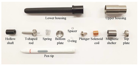
Figure 7.
Components for the proposed tiny haptic stylus.
3. Experiment of the Tiny Haptic Stylus
3.1. Experimental Setup
Figure 8 shows an experimental setup to evaluate the haptic performance of the proposed tiny haptic stylus. The experimental setup is composed of a PC and a universal testing machine (UTM, Z0.5, ZwickRoell, Ulm, Germany) including a load cell (Xforce P 100 N, Zwick Roell, Ulm, Germany), and a power supply. In order to tightly fix the proposed haptic stylus, we fabricated a mold (a sample holder), whose shape is exactly matched with the upper housing of the haptic stylus. The sample holder was made of stainless steel (SUS 301) for minimizing the distortion or deformation. The haptic stylus was bonded with the sample holder, which was bolted on the UTM, by super glue. The measurement head was precisely moved in the vertical (z-axis) direction by the linear motor installed in the UTM. When the measurement head pushes down the haptic stylus, the resistive force is measured through the load cell. The measured resistive force and the position of the measurement head were delivered and were stored on the PC. The experiment was conducted under various constant speed (0.1 mm/s, 0.5 mm/s, 1.0 mm/s, 2.0 mm/s, 5.0 mm/s, 10.0 mm/s, and 15.0 mm/s) of the measurement head. We set the offset when the contact force (0.01 N) from the load cell was measured. The power supply was connected to the proposed haptic stylus to control its resistive force. We measured the resistive forces by changing the input current, measurement head’s position, and varying the pressing speed.
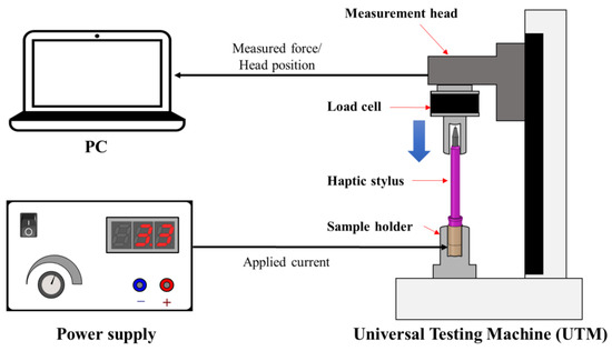
Figure 8.
Experimental setup to evaluate the haptic performance of a proposed tiny haptic stylus.
3.2. Experimental Results
Figure 9a shows the experimental results of the measured force with varying indented depths (from 0.01 mm to 1.0 mm) and with fixing pressing speed (0.1 mm/s). In Figure 9a, the black line is the result when the current is removed. The initial resistive force of the proposed haptic stylus indicates approximately 1 N under the overall pressed depth because of the return spring and viscosity of MR fluid. The pink line is the result when the current (180 mA) is applied to the proposed tiny haptic stylus. Under the current input (180 mA), the measured resistive force gradually increases (from 2.33 N at 0.01 mm to 27.47 N at 1.0 mm) as the indented depth increases. For example, when the proposed haptic stylus is pressed 1.0 mm, the resistive force, which was initially 2.33 N, increases to 27.47 N in providing a current input of 180 mA. Theoretically, considering a human’s Just Noticeable Difference (JND) of approximately 10% [20], the proposed haptic stylus allows users to distinguish more than 26 steps of resistive force. It means that the proposed haptic stylus can convey a variety of kinesthetic sensations when a user interacts with virtual reality contents in a mobile device. We also verified that the resistive force variation can be easily adjusted by changing the input current. Figure 9b shows the results of the measured resistive force with respect to the pressing depth (varied from 0 mm to 1 mm) and the pressing speed (0.1 mm/s, 0.5 mm/s, 1.0 mm/s, 2.0 mm/s, 5.0 mm/s, 10.0 mm/s, and 15.0 mm/s). The resistive force generated from the proposed haptic stylus was measured with a constant input voltage of 3.3 V (a consumed current is 180 mA). Even though the pressing speed increases, the measured resistive forces are almost similar to the reference data (0.1 mm/s).
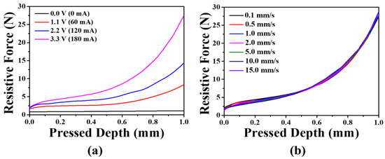
Figure 9.
Measured resistive force by pressing depth with varying input current at a constant pressing speed of 0.1 mm/s (a) and with varying pressing speed at a constant input current of 180 mA (b).
We investigated the response time of the proposed haptic stylus by applying a step input to the haptic stylus and measuring the time taken to reach 90% of the reference signal. In Figure 10, the blue solid line is the measured resistive force when a step input is applied. The response time (67 ms) was calculated by subtracting t1 (at the voltage is applied) from t2 (at the measured resistive force reaches a point of 90 % of the 3.3 V reference). The results show that the response time of the proposed haptic stylus is enough to be used for conventional haptic applications [21,22,23].
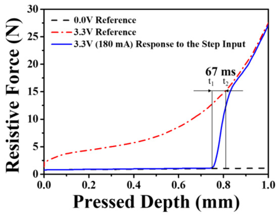
Figure 10.
Measured response time of the proposed haptic stylus.
4. Conclusions
A tiny haptic stylus based on MR fluids was presented as an interaction device for manipulating virtual reality contents in mobile devices. Compared to conventional haptic styluses, the proposed device can produce a large kinesthetic force in a small size. To maximize the large kinesthetic force in a small-sized stylus, the proposed design includes all three operation modes of MR fluids. We verified that the resistive force’s variation of the proposed haptic stylus was approximately 25.14 N (2.33 N–27.47 N) when the indented depth is varied from 0.01 mm to 1 mm. Moreover, we have found that the input voltage can change the resistive force of the proposed haptic stylus. Judging from the results, the proposed haptic stylus could be used as an interface device for manipulating virtual content in mobile devices. Some examples include touching rocks or cushion in virtual reality content; or conducting palpation training for medical students as medical education content. In order to maximize the performance of the proposed haptic stylus, we will develop the haptic rendering method and conduct a user study using the proposed haptic stylus. Furthermore, it may be possible to generate various haptic sensations by including a displacement or pressure sensor.
Author Contributions
Conceptualization, D.-S.C., S.B. and S.-Y.K.; Data curation, and S.B.; Formal analysis, D.-S.C. and T.-H.K.; Investigation, I.-H.Y. and S.B.; Visualization, D.-S.C.; Writing—original draft, S.-Y.K.; Writing—review and editing, S.-Y.K.; Authors 1 D.-S.C. and 2 I.-H.Y. contributed equally. All authors have read and agreed to the published version of the manuscript.
Funding
This work was supported by Priority Research Centers Program through the National Research Foundation of Korea (NRF) funded by the Ministry of Education, Science and Technology (NRF-2018R1A6A1A03025526). The study was also supported by the Technology Innovation Program (10077367, Development of a film-type transparent /stretchable 3D touch sensor haptic actuator combined module and advanced UI/UX) funded by the Ministry of Trade, Industry, and Energy (MOTIE, Sejong, Korea).
Acknowledgments
The authors thank the Cooperative Equipment Center at Koreatech for assistance with Universal Testing Machine (UTM) experiments.
Conflicts of Interest
The authors declare no conflict of interest.
References
- Lee, J.C.; Dietz, P.; Leigh, D.; Yerazunis, W.; Hudson, S.E. Haptic pen: A tactile feedback stylus for touch screens. In Proceedings of the ACM Symposium on User Interface Software and Technology (UIST) 2004, Santa Fe, NM, USA, 24–27 October 2004; pp. 291–294. [Google Scholar] [CrossRef]
- Kyung, K.; Lee, J.; Park, J. Ubi-Pen: Development of a compact tactile display module and its application to a haptic stylus. In Proceedings of the Second Joint EuroHaptics Conference and Symposium on Haptic Interfaces for Virtual Environment and Teleoperator Systems (WHC’07), Tsukaba, Japan, 22–24 March 2007; pp. 109–114. [Google Scholar] [CrossRef]
- Kyung, K.; Lee, J.; Park, J. Haptic stylus and empirical studies on braille, button, and texture display. J. Biomed. Biotechnol. 2008, 2008, 369651. [Google Scholar] [CrossRef] [PubMed]
- Liao, C.; Guimbretière, F.; Loeckenhoff, C.E. Pen-top feedback for paper-based interfaces. In Proceedings of the ACM Symposium on User Interface Software and Technology (UIST), New York, NY, USA, 15–18 October 2006; pp. 201–210. [Google Scholar] [CrossRef]
- Cho, Y.; Bianchi, A.; Marquardt, N.; Bianchi-Berthouze, N. RealPen: Providing realism in handwriting tasks on touch surfaces using auditory-tactile feedback. In Proceedings of the ACM Symposium on User Interface Software and Technology (UIST), Tokyo, Japan, 16–19 October 2016; pp. 195–205. [Google Scholar] [CrossRef]
- Wang, Q.; Ren, X.; Sun, X. Enhancing pen-based interaction using electrovibration and vibration haptic feedback. In Proceedings of the ACM CHI Conference on Human Factors in Computing Systems, New York, NY, USA, 6–11 May 2017; pp. 3746–3750. [Google Scholar] [CrossRef]
- Arasan, A.; Basdogan, C.; Sezgin, T.M. Haptic stylus with inertial and vibro-tactile feedback. In Proceedings of the IEEE World Haptics Conference, Daejeon, Korea, 14–17 April 2013; pp. 425–430. [Google Scholar] [CrossRef]
- Kamuro, S.; Minamizawa, K.; Kawakami, N.; Tachi, S. Ungrounded kinesthetic pen for haptic interaction with virtual environments. In Proceedings of the IEEE International Symposium on Robot and Human Interactive Communication, Toyama, Japan, 27 September–2 October 2009; pp. 436–441. [Google Scholar] [CrossRef]
- Tian, L.; Song, A.; Chen, D. A novel haptic stylus for mobile terminal. In Proceedings of the EuroHaptics, London, UK, 4–7 July 2016; pp. 338–349. [Google Scholar] [CrossRef]
- Kianzad, S.; MacLean, K.E. Collaborating through magic pens: Grounded forces in large, overlappable workspaces. In Proceedings of the AsiaHaptics, Incheon, Korea, 14–16 November 2018; pp. 233–237. [Google Scholar] [CrossRef]
- Kara, O.C.; Patoglu, V. VnStylus: A haptic stylus with variable tip compliance. IEEE Trans. Haptics 2020. Early Access. [Google Scholar] [CrossRef] [PubMed]
- Chen, D.; Song, A.; Tian, L. A novel miniature multi-mode haptic pen for image interaction on mobile terminal. In Proceedings of the IEEE International Symposium on Interaction on Mobile Terminal Haptic, Audio and Visual Environments and Games (HAVE), Ottawa, ON, Canada, 11 October 2015; pp. 1–6. [Google Scholar] [CrossRef]
- Chen, D.; Song, A.; Tian, L.; Yu, Y.; Zhu, L. MH-Pen: A pen-type multi-mode haptic interface for touch screens interaction. IEEE Trans. Haptics 2018, 11, 555–567. [Google Scholar] [CrossRef] [PubMed]
- Carlson, J.D.; Jolly, M.R. MR fluid, foam and elastomer devices. Mechatronics 2000, 10, 555–569. [Google Scholar] [CrossRef]
- Boelter, R.; Janocha, H. Design rules for MR fluid actuators in different working modes. In Proceedings of the Volume 3045, Smart Structures and Materials 1997: Passive Damping and Isolation, San Diego, CA, USA, 3–6 March 1997; pp. 148–159. [Google Scholar] [CrossRef]
- Yang, T.-H.; Koo, J.H.; Kim, S.-Y.; Kyung, K.-U.; Kwon, D.-S. A miniature magneto-rheological actuator with an impedance sensing mechanism for haptic applications. J. Intell. Mater. Syst. Struct. 2013, 25, 1054–1061. [Google Scholar] [CrossRef]
- Yang, T.-H.; Koo, J.H. Experimental evaluation of a miniature MR device for a wide range of human perceivable haptic sensations. Smart. Mater. Struct. 2017, 26, 125006. [Google Scholar] [CrossRef]
- Brigley, M.; Choi, Y.-T.; Wereley, N.M.; Choi, S.-B. Magnetorheological isolators using multiple fluid modes. J. Intell. Mater. Syst. Struct. 2007, 18, 1143–1148. [Google Scholar] [CrossRef]
- Grunwald, A.; Olabi, A.G. Design of magneto-rheological (MR) valve. Sens. Actuators A Phys. 2008, 148, 211–223. [Google Scholar] [CrossRef]
- Jones, L.A. Kinesthetic sensing. In Human and Machine Haptics; MIT Press: Cambridge, MA, USA, 2000. [Google Scholar]
- Immersion, UX Impacts of Haptic Latency in Automotive Interfaces. Available online: https://pdfs.semanticscholar.org/de7c/0c19188642cc925c256608f048163ea5973d.pdf (accessed on 28 August 2019).
- GNOME. GNOME Human Interface Guidelines 2.2.3/ Feedback. Available online: https://developer.gnome.org/hig-book/unstable/feedback-response-times.html.en (accessed on 28 August 2019).
- Nielsen Norman Group. Response Times: The 3 Important Limits. Available online: https://www.nngroup.com/articles/response-times-3-important-limits/ (accessed on 28 August 2019).


© 2020 by the authors. Licensee MDPI, Basel, Switzerland. This article is an open access article distributed under the terms and conditions of the Creative Commons Attribution (CC BY) license (http://creativecommons.org/licenses/by/4.0/).