A Novel Two Stage Controller for a DC-DC Boost Converter to Harvest Maximum Energy from the PV Power Generation


Abstract
1. Introduction
2. Photovoltaic System Model
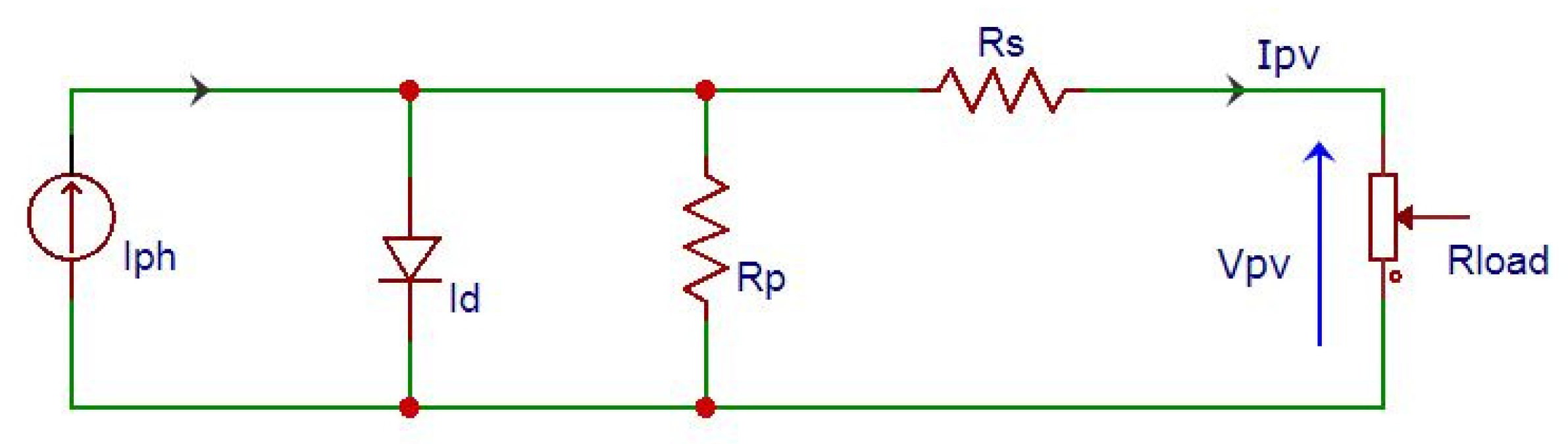
2.1. Photovoltaic Cell Modeling
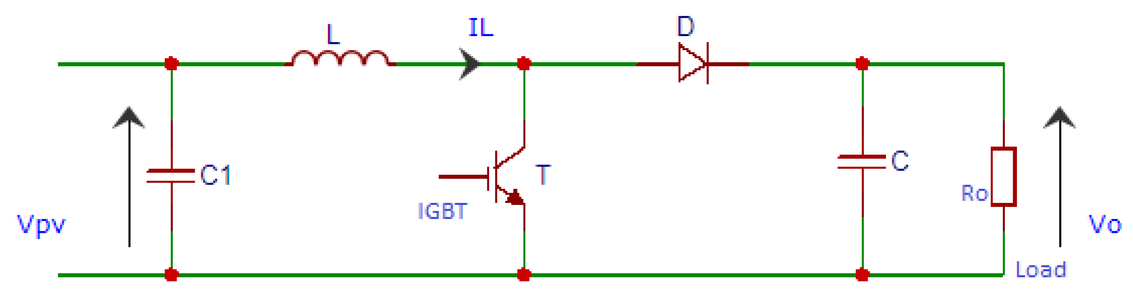
2.2. The Boost Converter Model
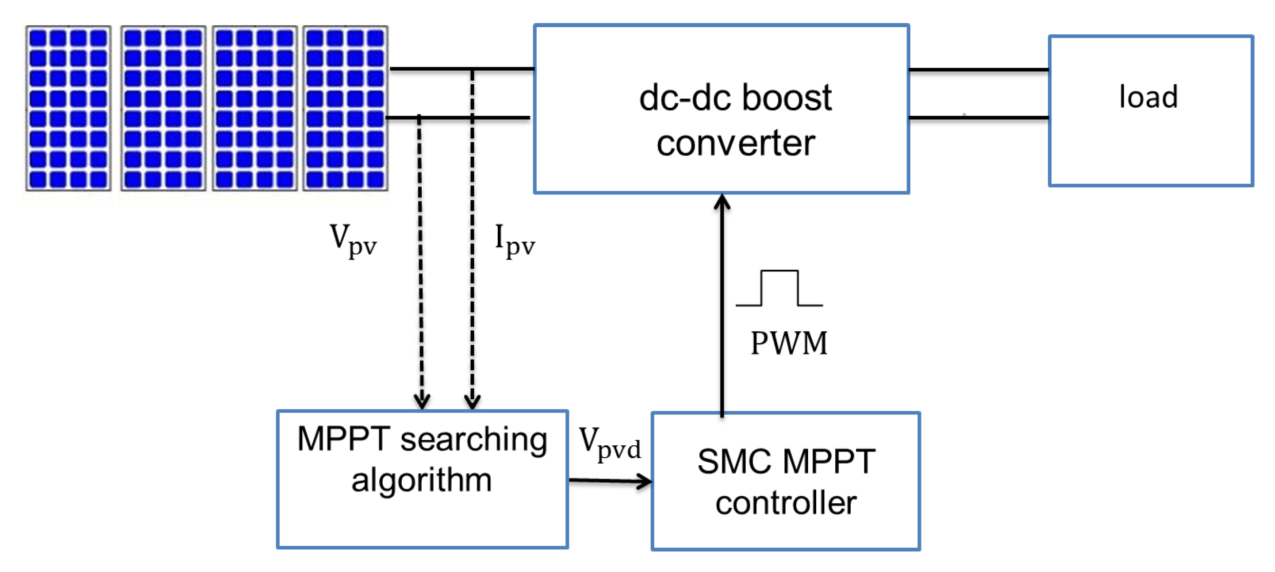
3. Control Design of The Proposed Two-Stage MPPT Algorithm
3.1. MPP Searching Algorithm
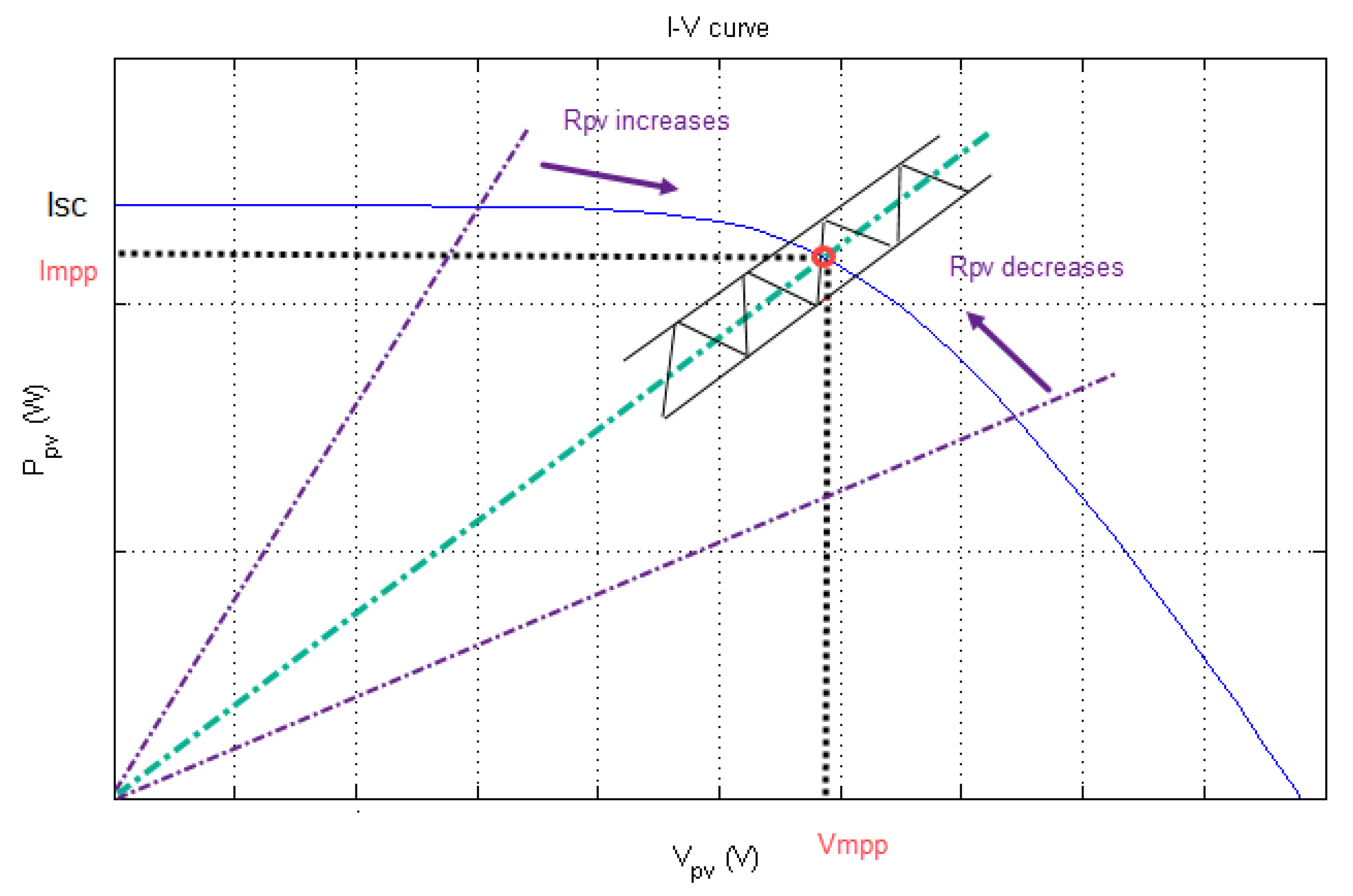
- Case 1:is the difference of the present power minus the previous and is also the gap among the actual PV voltage and the previous one . In Case 1, both and are positive. Therefore, the algorithm decreases the duty cycle so that continues to rise to reach MPP.
- Case 2:Here, is positive while is negative; referring to Figure 5, the PV module is working in the right of MPP. The algorithm’s action is to decrease the PV voltage by increasing the duty cycle until MPP is reached.
- Case 3:In this case, both and are negative. The control decision is to reduce the duty cycle to raise the PV voltage until reaching MPP.
- Case 4:In the last case, is negative while is positive. The decision assumed is to increase the duty ratio to lead the decreasing of the PV voltage .
3.2. Sliding Mode Controller
- When : This denotes that the voltage reference provided by the MPP searching algorithm based on P&O is bigger than the PV voltage of the PV module, i.e., . Afterwards, this leads s to zero , meaning . As shown in Figure 5, should increase and should decrease; therefore, as a result, must increase through decreasing the duty cycle , which is deduced from Equation (9).As a conclusion, the system is stable when is increased, which implies that , then , and our system moves toward the maximum power point.
- When : Based on Equation (10), ; thus, to stabilize our system and according to Figure 5, must decrease and should increase. Therefore, has to drop, which occurs through raising the duty ratio , denoting that and .Finally, based on Lyapunov stability theory, we deduce that the control law is stabilizing.
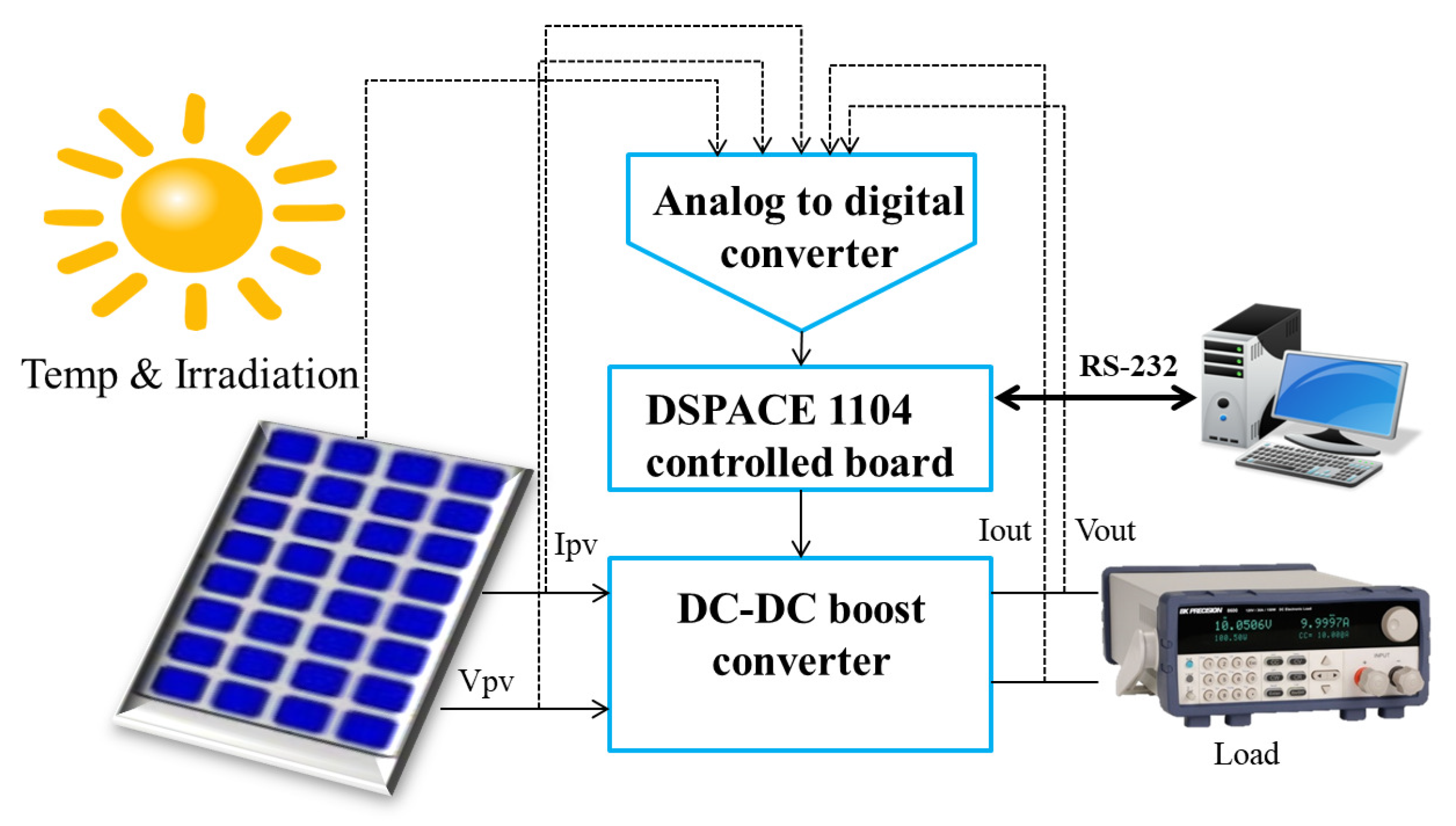
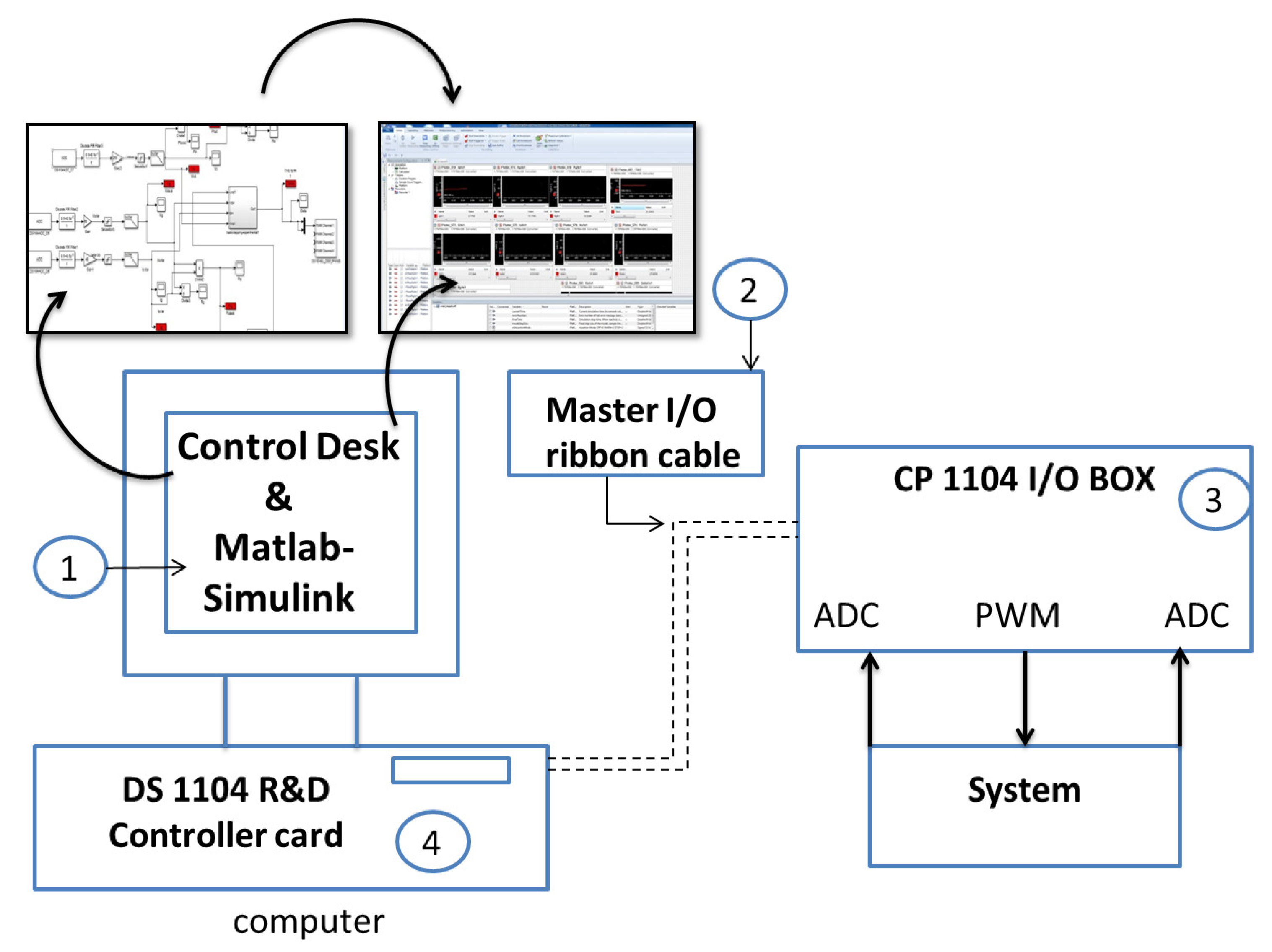
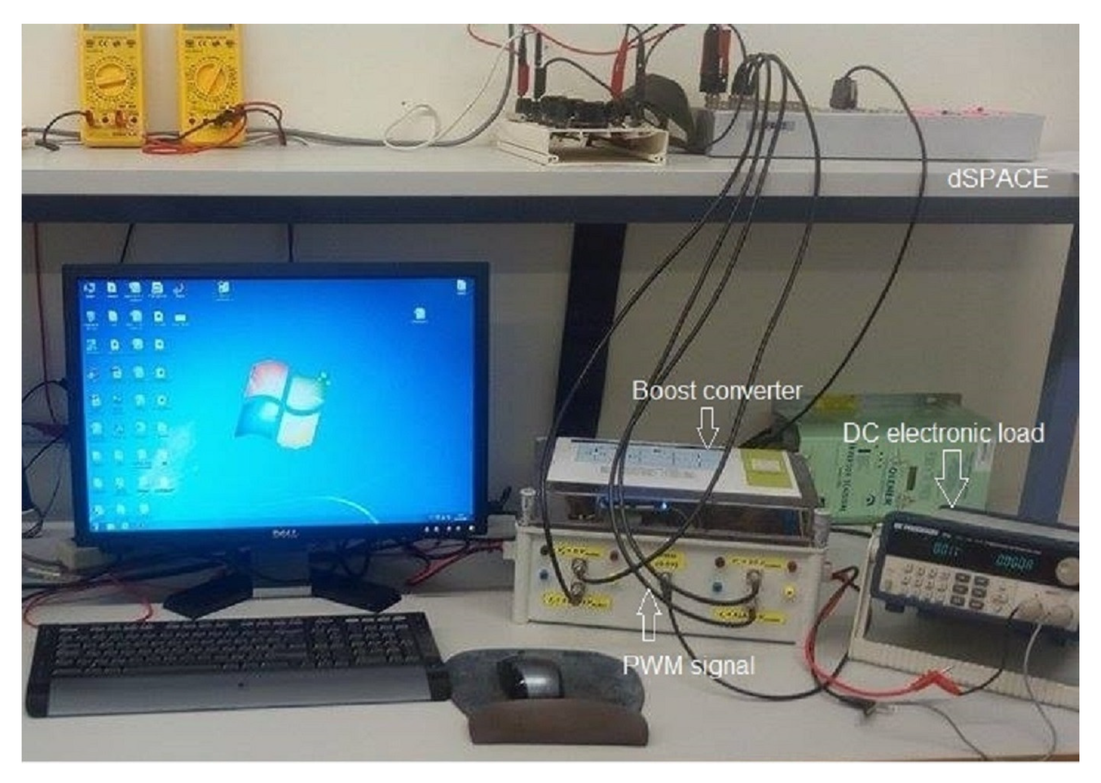
4. Instrumentation Used in Real Time Experiments
4.1. Atersa PV Panel
4.2. Boost Converter
4.3. DSP1104
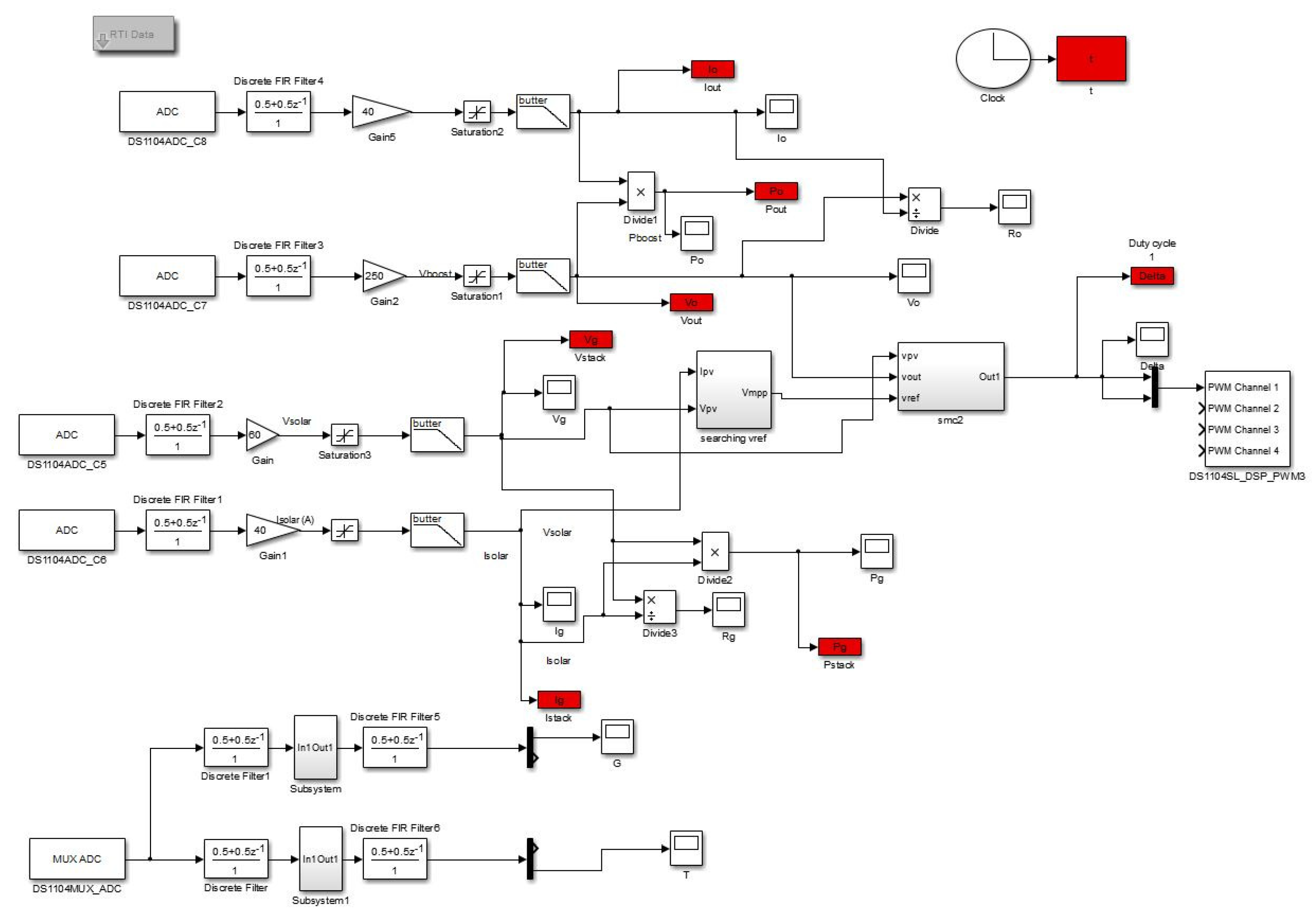
- Matlab/Simulink and Control Desk:The software packages used in the experimental test are Matlab-Simulink and Control Desk 5.1. Indeed, the way we made our control strategies is the same as making any Simulink project, by using basics blocs or toolboxes via installing the library RTI 1104 in Simulink-Matlab. Thereafter, we compiled the Simulink model and generated a (.sdf) file, which is a specific code in real time.Control Desk 5.1 is wasused for creating an interface with the GUI (graphical user interface). Figure 6 illustrates how the real-time code is obtained from (.sdf) file generated from Simulink, which allows us to access and modify the variable control system in real time.
- I/O ribbon cable:It is used to connect the DS1104 R&D controller card to the I/O box.
- CP 1104 I/O box:It is an input/output interface board between the DS1104 R&D controller board and the system.It contains eight analog input digital converters (ADCs), eight analog output digital converters, and two digital input incremental encoders.
- DS1104 R&D controlled board:This board is installed in the computer and connected to the CP 1104 I/O through a master I/O ribbon cable. The DS1104 runs with Power PC 603e core at 250 MHz with 32 MB of SDRAM and 8 MB of flash memory.
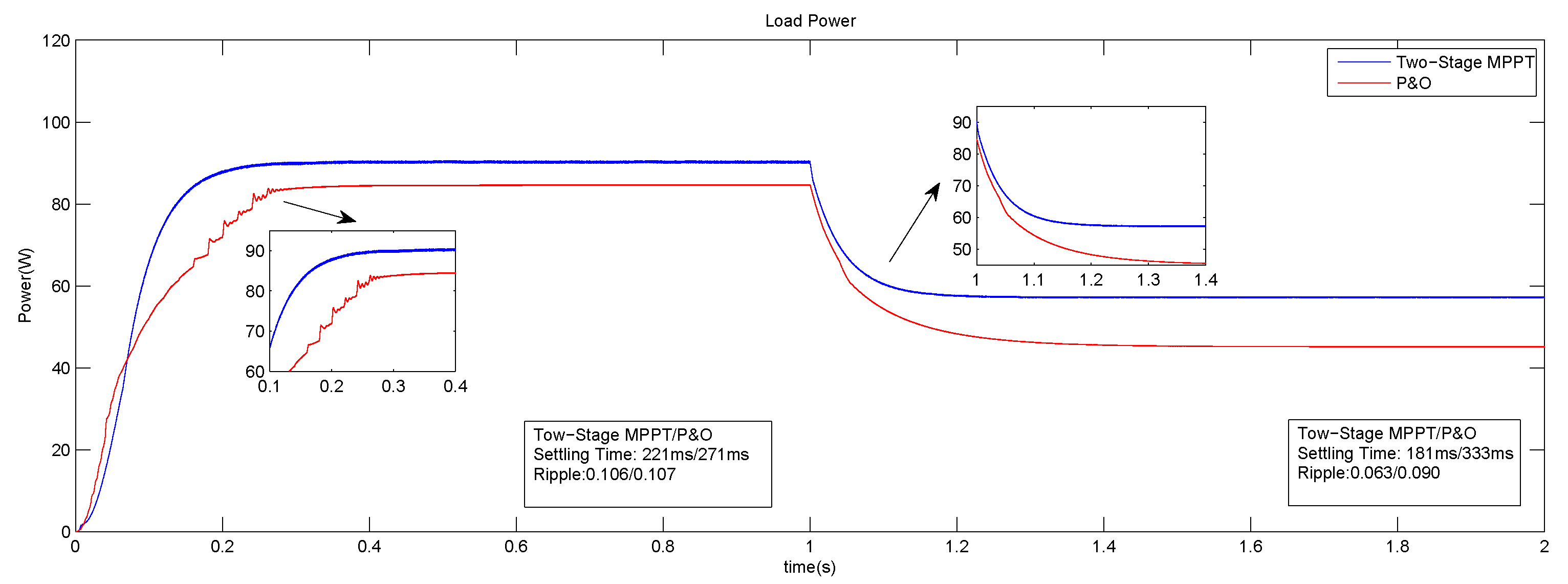
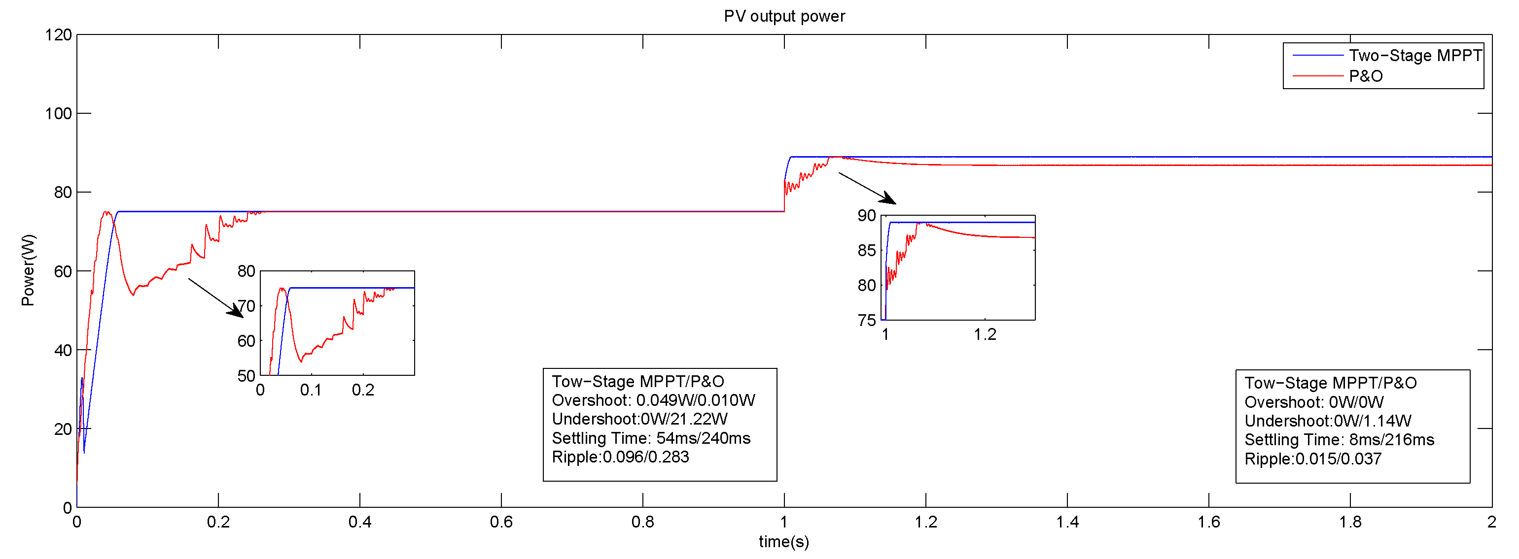
5. Simulation Results
5.1. Effects of Parasitic Components
5.2. Simulation under Steady Temperature
5.3. Simulation at Steady Irradiation
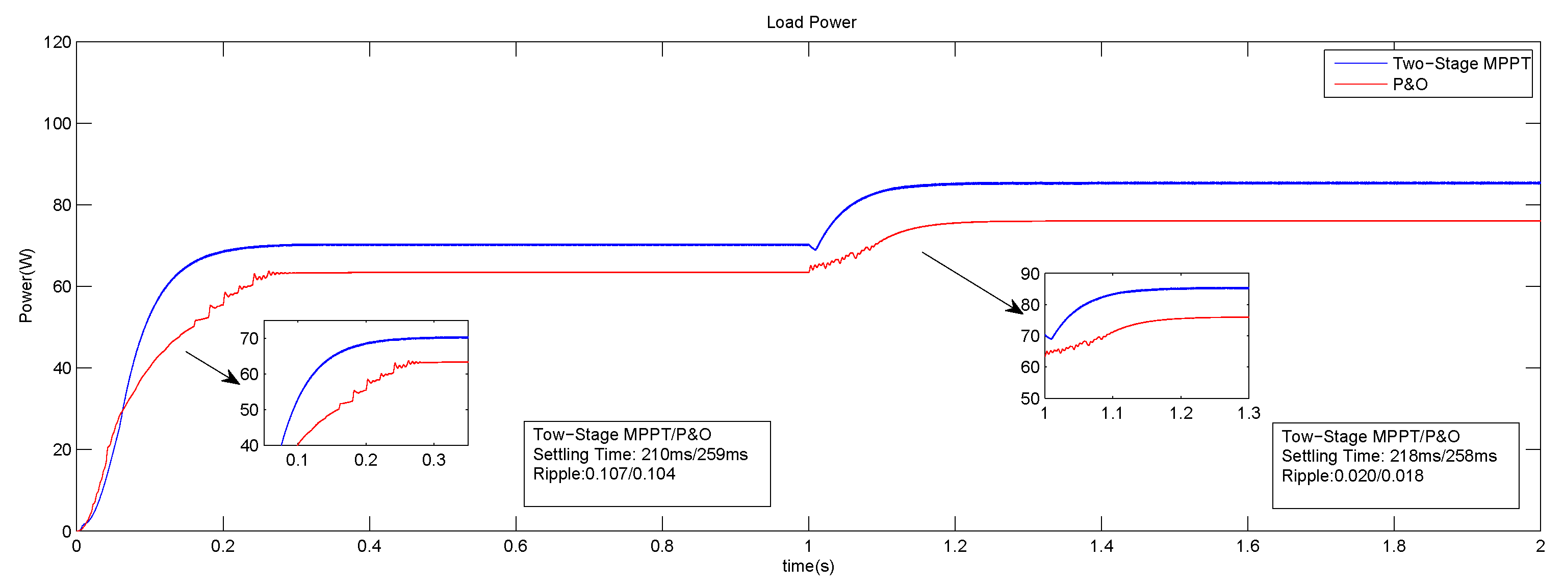
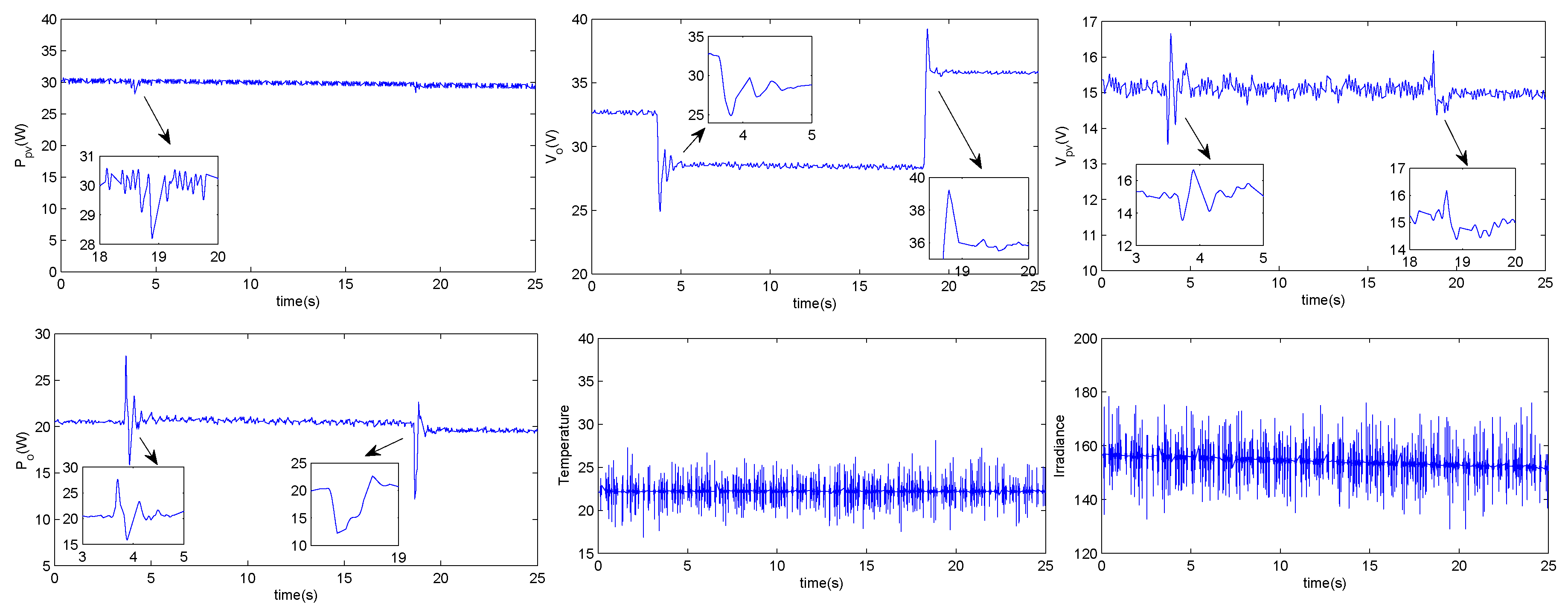
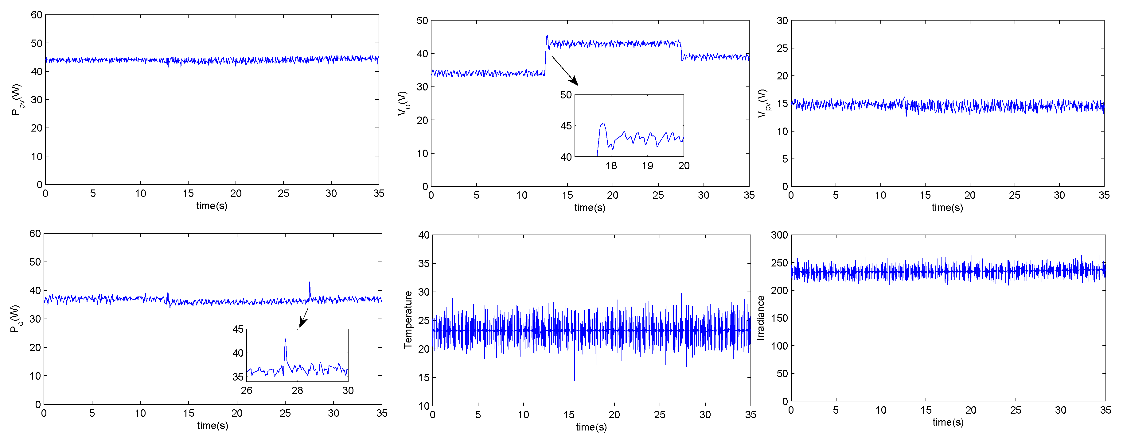
6. Experimental Results and Discussion
- DS1104_Mux_ADC DS1104: This block is for reading the four A/D converter channels. The two algorithms only need the irradiation (G) and the temperature (T) at every sample time.
- DS1104_ADC_CX: It is devoted to reading the data of the four signals from (ADC_C5 to ADC_C8). ADC_C5 is dedicated to reading the photovoltaic voltage (=), ADC_C6 to reading the photovoltaic current (=), ADC_C7 to , and ADC_C8 to .
- DS1104SL_DSP_PWM3: It allows generating standard PWM pulses.
- Low pass filters: They are used to remove the undesirable high-frequency noise.
6.1. Perturbation and Observation Algorithm
6.2. Two-Stage MPPT Control
7. Conclusions and Perspectives
Author Contributions
Funding
Acknowledgments
Conflicts of Interest
Abbreviations
| MPPT | Maximum power point tracking |
| PV | Photovoltaic |
| MPP | Maximum power point |
| P&O | Perturbation and observation |
| DSP | Digital signal processor |
| MPV | Maximum power voltage |
| FLC | Fuzzy logic control |
| SMC | Sliding mode control |
| ADC | Analog to Digital Converter |
| DAC | Digital to Analog Converter |
References
- Kaushika, N.D.; Mishra, A.; Rai, A.K. Introduction to Solar Photovoltaic Power. In Solar Photovoltaics: Technology, System Design, Reliability and Viability; Springer International Publishing: Cham, Germany; New Delhi, India, 2018; pp. 1–14. [Google Scholar]
- Nema, P.; Nema, R.; Rangnekar, S. A current and future state of art development of hybrid energy system using wind and PV-solar: A review. Renew. Sustainable Energy Rev. 2009, 13, 2096–2103. [Google Scholar] [CrossRef]
- Sandelic, M.; Sangwongwanich, A.; Blaabjerg, F. Reliability Evaluation of PV Systems with Integrated Battery Energy Storage Systems: DC-Coupled and AC-Coupled Configurations. Electronics 2019, 8, 1059. [Google Scholar] [CrossRef]
- Eccher, M.; Salemi, A.; Turrini, S.; Brusa, R. Measurements of power transfer efficiency in CPV cell-array models using individual DC–DC converters. Appl. Energy 2015, 142, 396–406. [Google Scholar] [CrossRef]
- Valencia, P.A.O.; Ramos-Paja, C.A. Sliding-Mode Controller for Maximum Power Point Tracking in Grid-Connected Photovoltaic Systems. Energies 2015, 8, 12363–12387. [Google Scholar] [CrossRef]
- Singh, O.; Gupta, S.K. A review on recent Mppt techniques for photovoltaic system. In Proceedings of the 2018 IEEMA Engineer Infinite Conference (eTechNxT), New Delhi, India, 13–14 March 2018; pp. 1–6. [Google Scholar]
- Subudhi, B.; Pradhan, R. A comparative study on maximum power point tracking techniques for photovoltaic power systems. IEEE Trans. Sustainable Energy 2013, 4, 89–98. [Google Scholar] [CrossRef]
- Bendib, B.; Belmili, H.; Krim, F. A survey of the most used MPPT methods: Conventional and advanced algorithms applied for photovoltaic systems. Renew. Sustainable Energy Rev. 2015, 45, 637–648. [Google Scholar] [CrossRef]
- Munteanu, I.; Bratcu, A.I. MPPT for grid-connected photovoltaic systems using ripple-based Extremum Seeking Control: Analysis and control design issues. Sol. Energy 2015, 111, 30–42. [Google Scholar] [CrossRef]
- Twaha, S.; Zhu, J.; Maraaba, L.; Huang, K.; Li, B.; Yan, Y. Maximum Power Point Tracking Control of a Thermoelectric Generation System Using the Extremum Seeking Control Method. Energies 2017, 10, 2016. [Google Scholar] [CrossRef]
- Ishaque, K.; Salam, Z.; Lauss, G. The performance of perturb and observe and incremental conductance maximum power point tracking method under dynamic weather conditions. Appl. Energy 2014, 119, 228–236. [Google Scholar] [CrossRef]
- Basha, C.H.; Rani, C. Different Conventional and Soft Computing MPPT Techniques for Solar PV Systems with High Step-Up Boost Converters: A Comprehensive Analysis. Energies 2020, 13, 371. [Google Scholar] [CrossRef]
- Safari, A.; Mekhilef, S. Simulation and hardware implementation of incremental conductance MPPT with direct control method using cuk converter. IEEE Trans. Ind. Electron. 2011, 58, 1154–1161. [Google Scholar] [CrossRef]
- Sivakumar, P.; Kader, A.A.; Kaliavaradhan, Y.; Arutchelvi, M. Analysis and enhancement of PV efficiency with incremental conductance MPPT technique under non-linear loading conditions. Renew. Energy 2015, 81, 543–550. [Google Scholar] [CrossRef]
- Yang, C.Y.; Hsieh, C.Y.; Feng, F.K.; Chen, K.H. Highly efficient analog maximum power point tracking (AMPPT) in a photovoltaic system. IEEE Trans. Circuits Syst. Regul. Pap. 2012, 59, 1546–1556. [Google Scholar] [CrossRef]
- Koizumi, H.; Kurokawa, K. A novel maximum power point tracking method for PV module integrated converter. In Proceedings of the IEEE 36th Power Electronics Specialists Conference, Recife, Brazil, 16 June 2005; pp. 2081–2086. [Google Scholar]
- Jain, S.; Agarwal, V. A new algorithm for rapid tracking of approximate maximum power point in photovoltaic systems. IEEE Power Electron. Lett. 2004, 2, 16–19. [Google Scholar] [CrossRef]
- Moradi, M.H.; Reisi, A.R. A hybrid maximum power point tracking method for photovoltaic systems. Sol. Energy 2011, 85, 2965–2976. [Google Scholar] [CrossRef]
- Younis, M.A.; Khatib, T.; Najeeb, M.; Ariffin, A.M. An improved maximum power point tracking controller for PV systems using artificial neural network. Przegląd Elektrotechniczny 2012, 88, 116–121. [Google Scholar]
- D’Souza, N.S.; Lopes, L.A.; Liu, X. Comparative study of variable size perturbation and observation maximum power point trackers for PV systems. Electr. Power Syst. Res. 2010, 80, 296–305. [Google Scholar] [CrossRef]
- Dong, J.; Zhang, C.; Li, Y. Comparison of duty ratio perturbation & observation and reference voltage perturbation & observation methods applied in MPPT. In Proceedings of the 7th International Power Electronics and Motion Control Conference (IPEMC), Harbin, China, 2–5 June 2012; Volume 2, pp. 1358–1362. [Google Scholar]
- Al-Soeidat, M.R.; Cembrano, A.; Lu, D.D. Comparing effectiveness of hybrid mppt algorithms under partial shading conditions. In Proceedings of the 2016 IEEE International Conference on Power System Technology (POWERCON), Wollongong, Australia, 28 September–1 October 2016; pp. 1–6. [Google Scholar]
- Anto, E.K.; Asumadu, J.A.; Okyere, P.Y. PID control for improving P&O-MPPT performance of a grid-connected solar PV system with Ziegler-Nichols tuning method. In Proceedings of the 2016 IEEE 11th Conference on Industrial Electronics and Applications (ICIEA), Hefei, China, 5–7 June 2016; pp. 1847–1852. [Google Scholar]
- Abdelkader, B.; WAHID, B.A. Modeling and control of photovoltaic system using sliding mode controle, comparative studies with conventional controls. PrzegląD Elektrotechniczny 2020, 96. [Google Scholar] [CrossRef]
- Calanca, A.; Capisani, L.; Fiorini, P. Robust Force Control of Series Elastic Actuators. Actuators 2014, 3, 182–204. [Google Scholar] [CrossRef]
- Qi, H.; Bone, G.M.; Zhang, Y. Position Control of Pneumatic Actuators Using Three-Mode Discrete-Valued Model Predictive Control. Actuators 2019, 8, 56. [Google Scholar] [CrossRef]
- Gong, X.; Ge, W.; Yan, J.; Zhang, Y.; Gongye, X. Review on the Development, Control Method and Application Prospect of Brake-by-Wire Actuator. Actuators 2020, 9, 15. [Google Scholar] [CrossRef]
- Abdullaev, G.; BAKIROV, M.; Safarov, N. Silicon solar cells with antireflection layers of silicon oxide and nitride. Appl. Sol. Energy 1993, 29, 76–78. [Google Scholar]
- Reisi, A.R.; Moradi, M.H.; Jamasb, S. Classification and comparison of maximum power point tracking techniques for photovoltaic system: A review. Renew. Sustainable Energy Rev. 2013, 19, 433–443. [Google Scholar] [CrossRef]
- Lopez-Guede, J.M.; Ramos-Hernanz, J.A.; Zulueta, E.; Fernadez-Gamiz, U.; Oterino, F. Systematic modeling of photovoltaic modules based on artificial neural networks. Int. J. Hydrogen Energy 2016, 41, 12672–12687. [Google Scholar] [CrossRef]
- Walker, G. Evaluating MPPT converter topologies using a MATLAB PV model. J. Electr. Electron. Eng. Australia 2001, 21, 49. [Google Scholar]
- Hussein, K.; Muta, I.; Hoshino, T.; Osakada, M. Maximum photovoltaic power tracking: An algorithm for rapidly changing atmospheric conditions. IEE Proc. Gener. Transm. Distrib. 1995, 142, 59–64. [Google Scholar] [CrossRef]
- Zhang, H.; Yang, X.P.; Ma, X.K.; He, B. Analysis of limit cycle behavior in DC–DC boost converters. Nonlinear Anal. Real World Appl. 2012, 13, 2049–2062. [Google Scholar] [CrossRef]
- Asma, C.; Abdelaziz, Z.; Nadia, Z. Dual loop control of DC-DC boost converter based cascade sliding mode control. In Proceedings of the 2017 IEEE International Conference on Green Energy Conversion Systems (GECS), Hammamet, Tunisia, 23–25 March 2017; pp. 1–6. [Google Scholar]
- Zhang, F.; Thanapalan, K.; Procter, A.; Carr, S.; Maddy, J. Adaptive hybrid maximum power point tracking method for a photovoltaic system. IEEE Trans. Energy Convers. 2013, 28, 353–360. [Google Scholar] [CrossRef]
- Davoudi, A.; Jatskevich, J.; Chapman, P. Averaged modelling of switched-inductor cells considering conduction losses in discontinuous mode. IET Electr. Power Appl. 2007, 1, 402–406. [Google Scholar] [CrossRef]
- Luchetta, A.; Manetti, S.; Piccirilli, M.C.; Reatti, A.; Kazimierczuk, M.K. Comparison of DCM operated PWM DC-DC converter modelling methods including the effects of parasitic components on duty ratio constraint. In Proceedings of the 2015 IEEE 15th International Conference on Environment and Electrical Engineering (EEEIC), Rome, Italy, 10–13 June 2015; pp. 766–771. [Google Scholar]
- Locorotondo, E.; Pugi, L.; Corti, F.; Becchi, L.; Grasso, F. Analytical Model of Power MOSFET Switching Losses due to Parasitic Components. In Proceedings of the 2019 IEEE 5th International forum on Research and Technology for Society and Industry (RTSI), lorence, Italy, 9–12 September 2019; pp. 331–336. [Google Scholar]
- Reatti, A.; Corti, F.; Tesi, A.; Torlai, A.; Kazimierczuk, M.K. Effect of Parasitic Components on Dynamic Performance of Power Stages of DC-DC PWM Buck and Boost Converters in CCM. In Proceedings of the 2019 IEEE International Symposium on Circuits and Systems (ISCAS), Sapporo, Japan, 26–29 May 2019; pp. 1–5. [Google Scholar]


| Symbol | Definition |
|---|---|
| Photo current [A] | |
| Reverse saturation current [A] | |
| A | Ideality factor |
| Short circuit current [A] | |
| Open circuit voltage [V] | |
| Temperature coefficient of short circuit current [A/K] | |
| Cell temperature [K] | |
| Cell reference temperature [K] | |
| S | Solar irradiation [W/m2] |
| K | Boltzmann constant, [J/K] |
| Band gap energy [eV] | |
| q | Electron charge, [C] |
| Measurements | Voltage | Duty Cycle () |
|---|---|---|
| Rise | Drop | |
| Drop | Rise | |
| Rise | Drop | |
| Drop | Rise |
| Parameter | Value |
|---|---|
| Power (W in test ) | 55 W |
| 36 | |
| A | |
| V | |
| A | |
| V | |
| Temperature coefficient of | mA/ C |
| Temperature coefficient of | mV/ C |
| Parameter | Type | Value |
|---|---|---|
| L | 6xPCV-2-564-08 | 560 H, 7 A, 42 m |
| C | 2xTK Series | 1500 F, 250 V |
| 1xTK | 1000 F, 250 V | |
| Schottky diode | 2xMURF1560GT | 600 V, 15 A, V |
| IGBT | 1xHGT40N60B3 | 600 V, 40 A, V |
| 20 KHz | ||
| 60 V | ||
| 20 A | ||
| 250 V | ||
| 20 A | ||
| Settling Time 2% | Overshoot | Ripple | Efficiency | Error | ||||||
|---|---|---|---|---|---|---|---|---|---|---|
| P&O | Two-Stage MPPT | P&O | Two-Stage MPPT | P&O | Two-Stage MPPT | P&O | Two-Stage MPPT | P&O | Two-Stage MPPT | |
| Fast irradiance variation (W/m2): from (1):S = 700 to (2): S = 400 | ||||||||||
| (1) | 241 ms | 61 ms | 0.17 W | 0.12 W | 0.313 | 0.098 | 99.87 | 99.97 | 0.12 | 0.02 |
| (2) | 472 ms | 0 ms | 0.55 W | 0.02 W | 0.011 | no ripple | 90.26 | 99.92 | 9.73 | 0.08 |
| Fast temperature variation (°C) from (1):T = 45 to (2): T = 20 | ||||||||||
| (1) | 240 ms | 54 ms | 0.01 W | 0.04 W | 0.283 | 0.096 | 99.89 | 99.89 | 0.106 | 0.106 |
| (2) | 216 ms | 8 ms | 2.15 W | 0 W | 0.037 | 0.015 | 97.72 | 99.80 | 2.273 | 0.191 |
© 2020 by the authors. Licensee MDPI, Basel, Switzerland. This article is an open access article distributed under the terms and conditions of the Creative Commons Attribution (CC BY) license (http://creativecommons.org/licenses/by/4.0/).
Share and Cite
Charaabi, A.; Barambones, O.; Zaidi, A.; Zanzouri, N. A Novel Two Stage Controller for a DC-DC Boost Converter to Harvest Maximum Energy from the PV Power Generation. Actuators 2020, 9, 29. https://doi.org/10.3390/act9020029
Charaabi A, Barambones O, Zaidi A, Zanzouri N. A Novel Two Stage Controller for a DC-DC Boost Converter to Harvest Maximum Energy from the PV Power Generation. Actuators. 2020; 9(2):29. https://doi.org/10.3390/act9020029
Chicago/Turabian StyleCharaabi, Asma, Oscar Barambones, Abdelaziz Zaidi, and Nadia Zanzouri. 2020. "A Novel Two Stage Controller for a DC-DC Boost Converter to Harvest Maximum Energy from the PV Power Generation" Actuators 9, no. 2: 29. https://doi.org/10.3390/act9020029
APA StyleCharaabi, A., Barambones, O., Zaidi, A., & Zanzouri, N. (2020). A Novel Two Stage Controller for a DC-DC Boost Converter to Harvest Maximum Energy from the PV Power Generation. Actuators, 9(2), 29. https://doi.org/10.3390/act9020029