1. Introduction
With the rapid advancement of UAV technology, multirotor UAVs have become increasingly important in military, civil, and industrial applications, owing to their capabilities for vertical takeoff and landing, hovering, and agile maneuvering [
1]. In particular, Hexarotor UAVs, thanks to their redundant propulsion configuration and high load capacity, are often the platform of choice for demanding mission environments [
2]. Currently, the majority of research on flight control systems relies on accurate mathematical modeling. For instance, Ru, P. and colleagues systematically derived the nonlinear dynamics of multirotor UAVs (in the form of state-dependent coefficients) and strictly proved the boundedness of tracking errors, highlighting the dependence on precise modeling [
3]. However, uncertainties like external disturbances introduce discrepancies between mathematical models and real-world situations, making it challenging for conventional control methods to achieve the required levels of accuracy and reliability [
4,
5]. Consequently, research on optimizing position and attitude control algorithms for Hexarotor UAVs holds considerable theoretical significance and practical value.
Many researchers around the world have explored the stability control of multirotor UAVs using a wide range of control strategies [
6,
7,
8,
9]. Early UAV control mainly relied on Proportional–Integral–Derivative (PID) controllers [
10,
11]; however, this approach suffers from poor disturbance rejection and is prone to overshoot or steady-state errors. The sliding mode control algorithm was introduced to UAVs by Aghdam, A.G.’s team [
12,
13], but it failed to address the problem of high-frequency chattering. Teams from Stanford and MIT utilized Linear Quadratic Regulators (LQR) for robust UAV control [
14]. However, the method struggles with nonlinearities, leading to limited disturbance rejection capability. However, J.P.’s team implemented Model Reference Adaptive Control (MRAC) for UAV attitude control [
15], yet this approach demands substantial computational resources and depends on high-performance processors. At ETH Zurich, Andrea, R.D.’s group employed Model Predictive Control (MPC) for obstacle avoidance and trajectory optimization in UAVs [
16]; however, performance degradation caused by model mismatch remained unresolved. Multirotor UAVs are inherently nonlinear and underactuated systems, so single control strategies typically struggle with disturbance rejection, nonlinearity, and multivariable coupling challenges.
A wide array of control schemes for position trajectory tracking of multirotor UAVs has been developed by researchers worldwide. Elhennawy, A.M. et al. designed a second-order sliding mode nonlinear controller to address
z-axis disturbances in quadrotor UAVs. This controller comprises two sub-controllers, targeting fully actuated and underactuated degrees of freedom, respectively, which effectively mitigated the chattering issues typical of sliding mode control [
17]. However, this approach demands high model fidelity, and any model inaccuracies or unmodeled dynamics can result in steady-state errors and degraded performance. To tackle the chattering and trajectory deviations caused by sensor noise and disturbances in conventional PID and MRAC controllers, Ahmed, Z. et al. systematically introduced Online Impedance Adaptive Control (OIAC) for multirotor UAVs. OIAC adaptively tunes impedance parameters in real time, substantially reducing high-order trajectory fluctuations and enhancing robustness to sensory noise [
18]. Nevertheless, the adaptation law incorporates several hyperparameters (e.g., a, b, initial impedance gains) and lacks a systematic online or automatic tuning strategy. Fatemi, M.M. et al. tackled the degradation in tracking accuracy caused by external disturbances and parameter variations by proposing an innovative control framework integrating Multi Layer Perceptron (MLP) neural networks with sliding mode controllers (SMC). The MLP’s online learning enables real-time adaptation of controller parameters, while the combined use of saturation functions and MLP-driven dynamic gain adjustment reduces high-frequency chattering and improves the smoothness of the system’s response [
19]. However, this method does not consider control under actuator faults or saturation, potentially limiting its robustness and fault tolerance in real-world scenarios. Addressing the challenge of UAV stability under intense wind disturbances in forested environments, Sadi, M.A. et al. decomposed the global MPC into “translation” and “rotation” subsystems. They formulated robust MPC cost functions and constraints to counter wind shear and turbulence, preserving the predictive benefits of MPC for coupled dynamics and enhancing position and attitude stability in turbulence [
20]. However, despite individual optimization of the subsystems, this approach may lose the global optimality, resulting in slightly inferior performance compared to global MPC, especially during highly coupled maneuvers.
Liu, K. et al. developed an observer-based adaptive fuzzy finite-time attitude control strategy for quadrotor UAVs operating under unavailable angular velocity, external disturbances, dynamic uncertainties, actuator faults, and input saturation. Numerical simulations showed that this approach offers strong robustness and anti-singularity properties [
21]. However, the adaptive fuzzy logic system depends heavily on manually designed membership functions and rule bases; the system’s performance is highly sensitive to these choices and typically relies on expert knowledge and iterative simulations, making automated tuning difficult. Lian, S. et al. developed a Fast Nonsingular Terminal Sliding Mode Angular Velocity Planning controller (FNTSM-AVP) to enable rapid post-disturbance attitude recovery. The controller restores roll and pitch to the desired attitudes along the shortest planned path and utilizes a continuous arctangent sliding surface to suppress chattering. Experiments confirmed that this method reduces overshoot, enhances tracking precision, and improves disturbance rejection for quadrotors [
22]. However, the control law and planning both rely on accurate inertial and aerodynamic models; discrepancies in parameter estimation can cause misalignment between the sliding surface and planned velocity path, requiring extensive simulation-based tuning. Wang, B. et al. proposed a baseline Terminal Sliding Mode Controller (TSMC) with known disturbance bounds to maintain attitude stability under actuator faults and parameter uncertainty, ensuring robust tracking under disturbances. Additionally, they introduced a neural network adaptive compensator to perform online estimation and correction of unknown parameter deviations [
23]. Nevertheless, the study only offers local convergence analysis for each subsystem; the complete closed-loop system lacks a unified Lyapunov criterion to rigorously guarantee global stability of the composite control strategy. Kurttisi, A. et al. tackled actuator time delays and unknown efficiency degradation in multirotor UAV attitude control by proposing an enhanced MRAC framework. Actuator time delays and efficiency factors are incorporated into the state-space model, forming reference and plant models that explicitly capture uncertainties. A Lyapunov-based adaptation law is then devised to adjust controller gains and estimate actuator efficiency in real time, compensating for errors due to thrust response lag and efficiency loss [
24]. However, MRAC’s adaptive law is highly sensitive to initial hyperparameter settings (such as learning rate and gain limits); improper tuning may result in transient overshoot or convergence delay when efficiency changes dramatically.
To tackle the challenges posed by large aerodynamic parameter variations and external disturbances encountered by hexarotor UAVs in flight [
25,
26], this study develops a hierarchical composite adaptive sliding mode control strategy to manage both the position and attitude of the UAV. First, a terminal sliding mode adaptive law is adopted to estimate and compensate for disturbances, and a robust terminal sliding mode controller is constructed to regulate the UAV’s position. Second, nonlinear decoupling of roll and pitch command angles from the position reference is performed to obtain the attitude command signals. Finally, the UAV’s attitude is controlled using a STSMC, where an adaptive term is incorporated to estimate and adjust the controller’s gain. This ensures optimal gain adjustment under the premise of robustness, ultimately guaranteeing global asymptotic stability of the hexarotor UAV in finite time.
2. Dynamic Model of Unmanned Aerial Vehicle
The hexarotor UAV features a simple structure and high maneuverability, powered by six brushless Direct Current (DC) motors [
27].
Figure 1 illustrates several common structural layouts for hexarotor UAVs. In
Figure 1a, the coaxial hexarotor configuration features three arms, each with two counter-rotating motors mounted coaxially at the tip. The overall structure resembles the letter “Y” with the upper and lower rotors responsible for lift generation and attitude adjustment, respectively [
28].
Figure 1b,c depict symmetric hexarotor layouts, where six rotors are evenly spaced at the vertices of a regular hexagon, each separated by 60 degrees. These rotors are typically divided into two groups—three rotating clockwise and three counterclockwise—arranged alternately to cancel the reaction torque. Specifically,
Figure 1b illustrates a cross-type symmetric hexarotor configuration, while
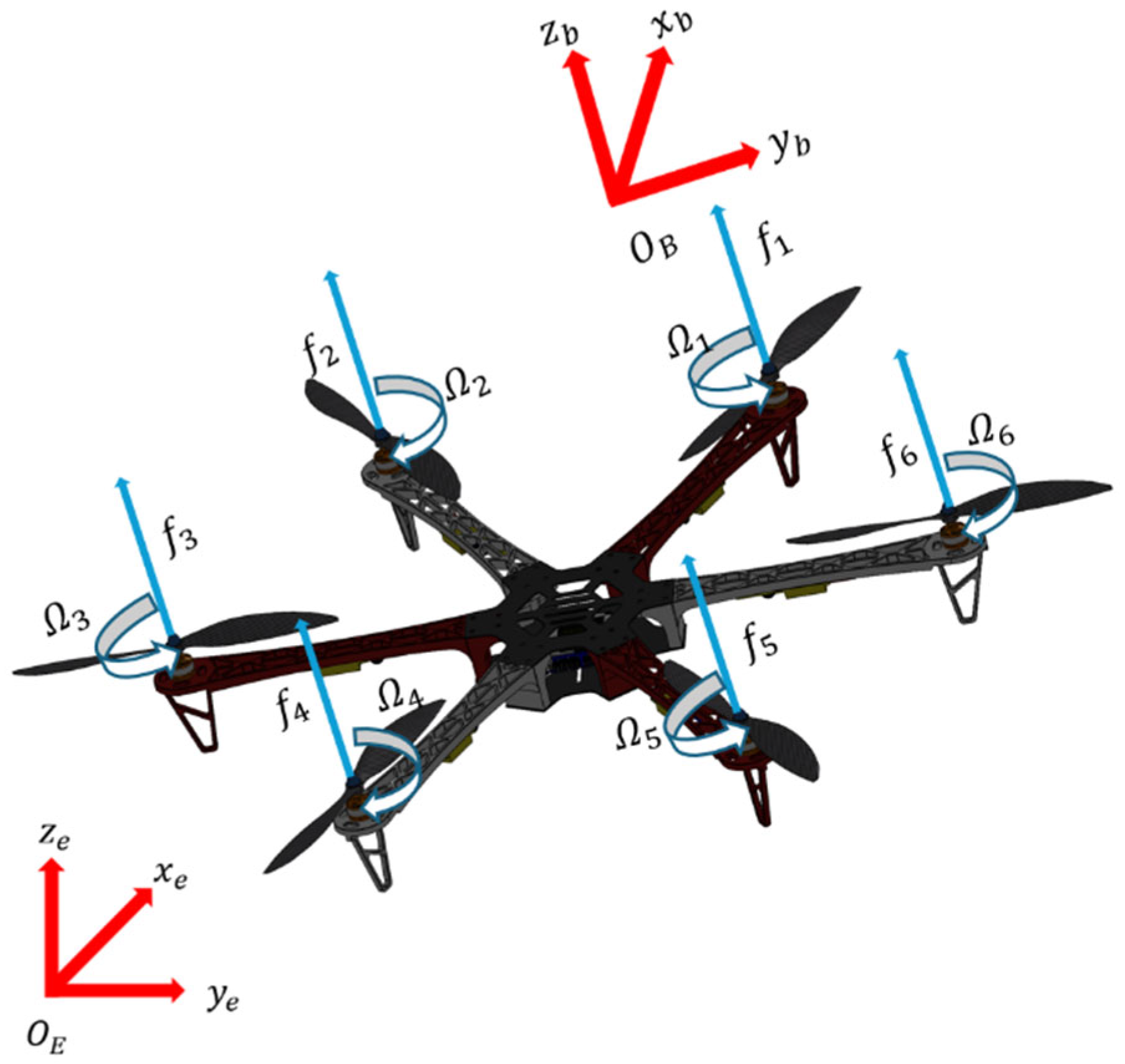
Figure 1c shows an X-type symmetric layout. In this paper, the flight principle is explained using the X-type symmetric hexarotor configuration, with the motor numbering as depicted in
Figure 2. The UAV’s flight state can be controlled by adjusting the rotational speed of the motors.
Table 1 summarizes the correspondence between flight states and motor speeds, with “+” indicating increased speed and “-” indicating decreased speed.
The structural schematic is illustrated in
Figure 2, where motors 1, 3, and 5 rotate counterclockwise and motors 2, 4, and 6 rotate clockwise.
denotes the total thrust generated by the UAV,
represents the rotational speed of each motor, and
is the thrust coefficient. The rotation of the motors produces a thrust vector that is perpendicular to the UAV’s body frame. By adjusting the rotational speeds of individual motors, the direction of the thrust vector can be altered, thereby enabling roll, pitch, and yaw maneuvers.
denotes the inertial coordinate frame, while
represents the body-fixed coordinate frame.
When the ground coordinate system is rotated by
degrees about the
axis, the transformation from the original to the new coordinate system can be described by the rotation matrix
. If the ground coordinate system rotates by
degrees about the
axis, the new-to-original coordinate transformation is given by the rotation matrix
. When the ground coordinate system is rotated by
degrees about the
axis, the corresponding transformation is described by the rotation matrix
. After the UAV has moved in space, the transformation matrix relating the body-fixed coordinate system to the ground coordinate system can be expressed as [
29]:
For stable position and attitude control of a hexarotor UAV under complex scenarios, it is essential to construct a precise mathematical model under idealized conditions. The ideal UAV model is assumed as follows:
Assumption 1. The hexarotor UAV is a rigid body with centrosymmetric geometry, uniform mass distribution, and no structural deformation.
Assumption 2. The lift generated by the hexarotor UAV is proportional to the square of the motor speed.
Assumption 3. All simulations in this paper were conducted under ideal conditions, disregarding aerodynamic drag, time delays, and other such effects.
2.1. Position Modeling
The position dynamics of the hexarotor UAV can be described by the following differential equations [
30]:
where
represents the position of the UAV,
denotes the velocity of the UAV,
is the mass of the UAV,
and denotes gravitational acceleration.
.
According to Newton’s second law:
By combining Equations (2)–(4), the kinematic mathematical model of the hexarotor UAV can be formulated as:
2.2. Attitude Modeling
The UAV’s attitude dynamics can be described by the following differential equations [
31].
where
represents the roll, pitch, and yaw angles of the UAV,
denotes the angular velocities of the UAV’s roll, pitch, and yaw,
is the moment of inertia,
denotes the distance from the UAV’s center of mass to the motor’s center of mass,
represents the aerodynamic torque acting on the UAV,
denotes the external disturbance acting on the attitude angles, and
denotes the transformation matrix between the angular velocity vector and the Euler angle vector in three axes.
As the UAV’s attitude angle variations are typically small during flight, the transformation matrix can be approximated as the identity matrix to simplify the mathematical model. The resulting expression is
By combining Equations (6)–(8), the dynamic mathematical model of the hexarotor UAV can be expressed as:
In the above equation, represents the lift coefficient of the motor, denotes the anti-torque (drag) coefficient, is the distance from the UAV’s center of mass to the motor’s center of mass, and denotes gravitational acceleration.
Lemma 1. Consider the system . If, for and , there exists a continuous positive definite function satisfying , then the system exhibits finite-time convergence, and the convergence time satisfies [32]: 3. Design of Position and Attitude Controllers Based on Hierarchical Composite Adaptive Sliding Mode Control
3.1. Introduction to Control Principles
Adaptive control is a technique that enables the online estimation or identification of unknown system parameters and dynamically adjusts the control law to ensure closed-loop performance and stability. It consists of two modules: a control law module and a parameter update module. The control law module generates control inputs based on current parameter estimates, while the parameter update module employs tracking errors to drive the estimation law and iteratively approach the true parameters. By designing a Lyapunov function, the adaptive law can achieve error convergence while guaranteeing system stability. When applied to multirotor UAVs, adaptive control offers several advantages: (1) Strong robustness: Adaptive control compensates online for parameter variations caused by time-varying factors such as payload and airflow, ensuring precise tracking. (2) Excellent disturbance rejection: By real-time estimation of external disturbances like wind and friction, adaptive controllers can swiftly adjust control inputs, enhancing disturbance rejection. (3) Low model dependence: Adaptive control does not require precise modeling, reducing design complexity and making it suitable for diverse UAV platforms and missions. (4) Adjustable convergence: The adaptation rate allows tuning of the learning speed, providing a flexible balance between convergence speed and noise immunity.
Sliding mode control is a variable structure control technique that enables rapid convergence of system states by designing a sliding surface, upon which the sliding mode is maintained under control action. Its core mechanism involves employing discontinuous control laws to force the system trajectory onto a predetermined sliding surface in finite time; by leveraging high-frequency switching, it counteracts model uncertainties and external disturbances, yielding strong robustness. Super-Twisting Sliding Mode Control (STSMC) is an advanced sliding mode control method for second-order systems. By introducing nonlinear integral components and adaptive mechanisms, it greatly mitigates the chattering associated with traditional sliding mode control while further improving robustness and control precision.
Consider the following second-order system:
Define the sliding surface as the following nonlinear combination of state errors.
The super-twisting sliding mode control law can then be formulated as [
33]:
In the above control law, the first term serves as a proportional component. When the system state is far from the sliding surface (∣s∣ is large), the ∣s∣
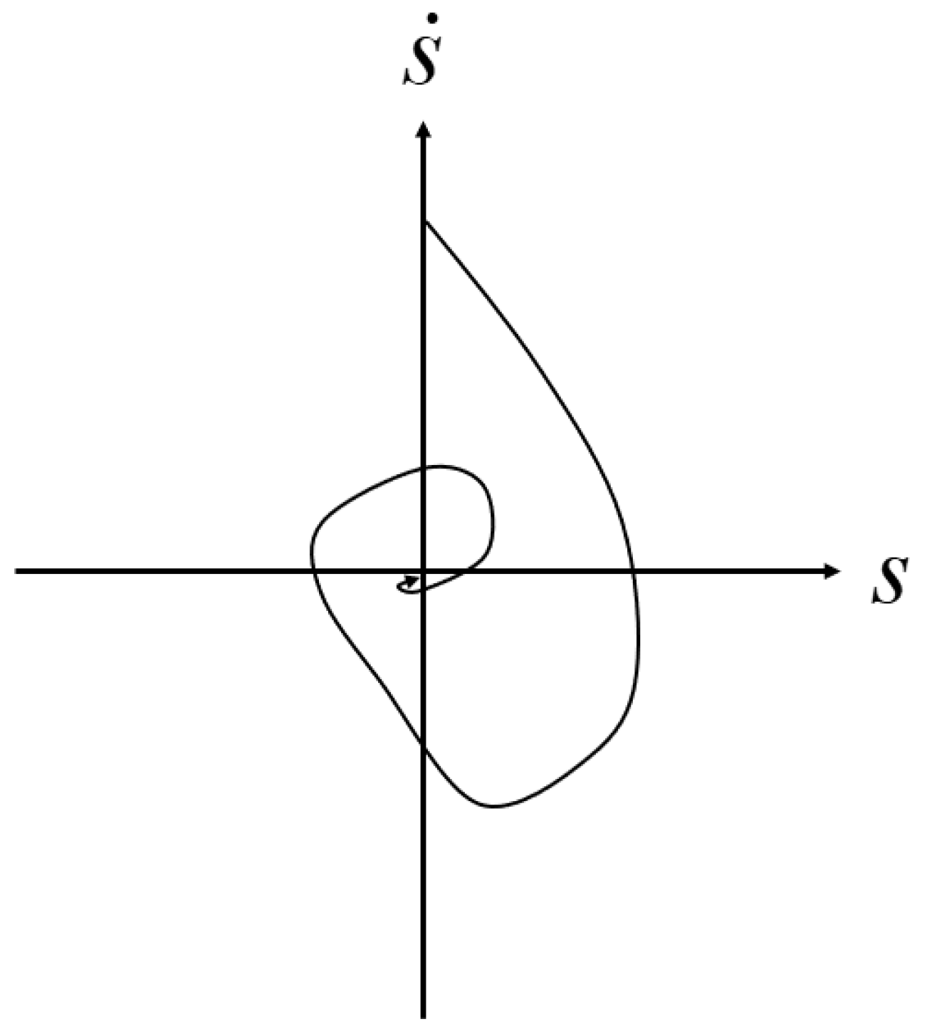
1/2 fractional power introduces a nonlinear gain, which accelerates the approach to the sliding surface. The second term is an integral component, which continuously accumulates historical error to compensate for external disturbances and parameter uncertainties. The resulting phase trajectory displays a “super-twisting” pattern, with the state quickly spiraling toward the sliding surface from its initial position, as shown in
Figure 3. This nonlinear convergence mechanism is driven by the proportional term of the control law; compared with the straight-line approach of traditional sliding mode control, the super-twisting trajectory shortens the convergence time.
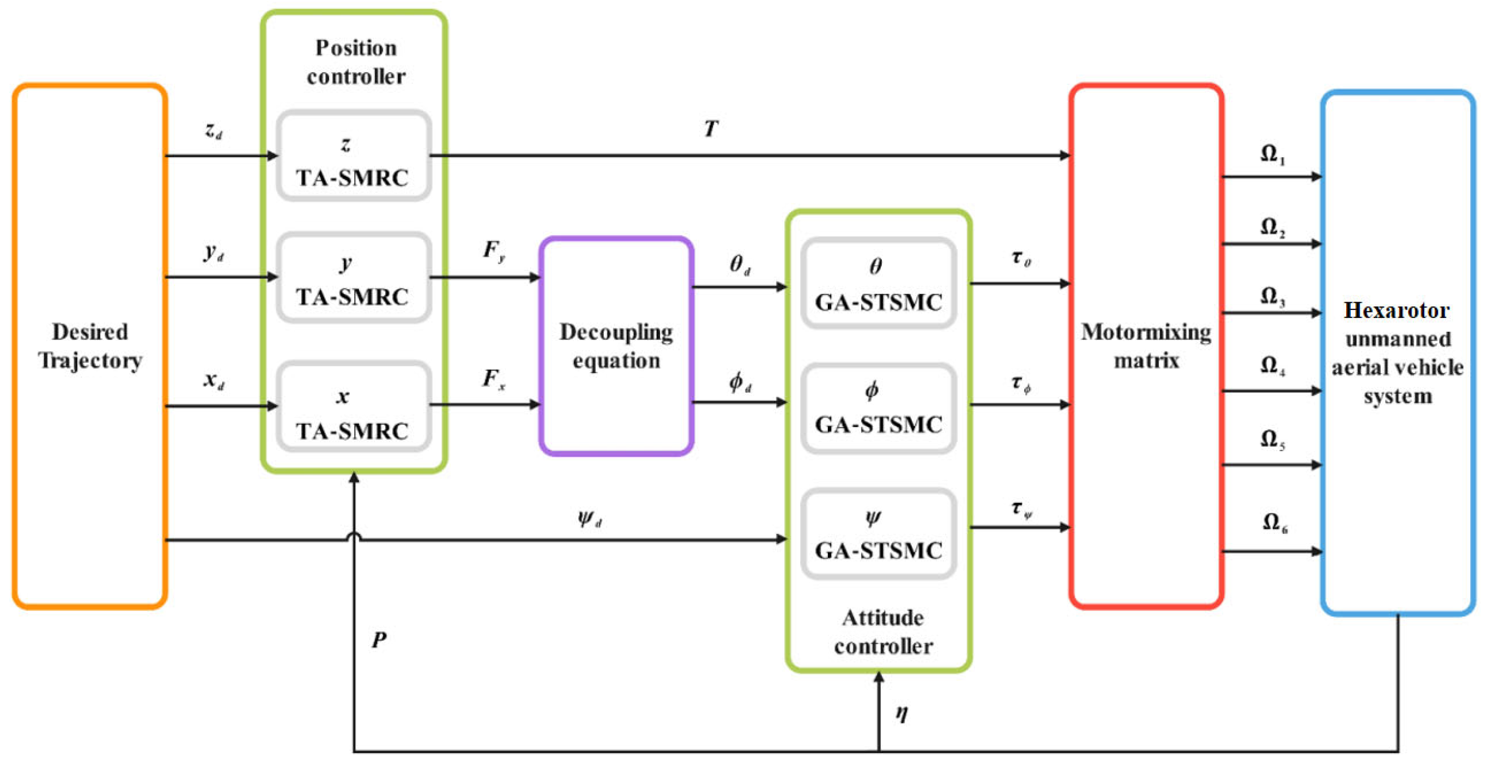
The hexarotor UAV system is nonlinear and underactuated, making it susceptible to external uncertainties. To ensure stable flight under complex conditions, a hierarchical composite control strategy is proposed. The control architecture is based on a decoupling control approach, with the position loop designed using a Terminal Adaptive Sliding Mode Robust Controller (TA-SMRC) and the attitude loop using a Gain-Adaptive Super-Twisting Sliding Mode Controller (GA-STSMC). Specifically, the position loop utilizes Terminal Sliding Mode Robust Control (TSMRC). To mitigate external uncertainties, an adaptive rate is designed to estimate external disturbances in real-time, enhancing the system’s ability to reject disturbances. The control law for the position channel is derived using Lyapunov stability theory, ensuring precise tracking of the UAV’s three-dimensional trajectory. Upon receiving the command signal, the flight controller outputs three-axis control quantities from the position loop, which are then converted into desired pitch, roll, and yaw commands by the attitude calculation module. The attitude loop is controlled by a STSMC, addressing the high-frequency chattering issue in traditional sliding mode control. An adaptive rate is used to adjust the STSMC gain in real-time, ensuring it reaches the optimal non-overestimated value. The resulting attitude control torque is calculated via inverse dynamics. Using the hexaotor UAV’s aerodynamic characteristics model, a quadratic mapping relationship between rotor lifts and rotational speed is developed. pulse-width modulation (PWM) is then used to achieve differential control of the six brushless motors, completing the coordinated control of the UAV’s six degrees of freedom. The block diagram of the control system is shown in
Figure 4.
3.2. Design of a Position Controller Based on TA-SMRC
To quantify the deviation between the actual and desired positions of the UAV, the position error of the hexarotor UAV is defined as follows:
where
denotes the desired position of the hexarotor UAV,
represents the position tracking error of the UAV. The derivative of the position error yields the velocity error, and further differentiation gives the acceleration error:
Based on the dynamic equations, to accelerate finite-time convergence and effectively suppress system uncertainties and external disturbances, a sign function is incorporated into the sliding surface, and the following terminal sliding surface is designed:
where
,
denotes the diagonal gain matrix, and
are the sign functions corresponding to the position errors along the x, y, and z axes, respectively. Taking the derivative of Equation (16) yields:
By substituting the position dynamics Equation (2) and the acceleration error Equation (15) into Equation (17), the first-order derivative equation of the sliding surface can be obtained:
Based on the sliding surface designed by Equation (16), the following robust control law is proposed to compensate for external disturbances and accelerate the convergence of the sliding surface:
where
denotes the diagonal sliding gain matrix,
is the external disturbance, and
is its estimated value. To achieve asymptotic tracking of external disturbances, a sign function of the sliding surface is introduced, and the following adaptive law is designed for real-time estimation of unknown disturbances:
where
denotes the adaptive gain.
3.3. Attitude Calculation for Hexarotor UAV
The flight stability and task execution capability of a hexarotor UAV rely heavily on the performance of its attitude control system. As a key part of the attitude control system, attitude calculation aims to transform the reference signals output by the position controller into specific attitude angle references. In other words, the desired acceleration or thrust direction from the position controller must be properly mapped to attitude commands, enabling the subsequent attitude controller to execute attitude adjustments. In the control structure of the UAV, the position controller outputs the required acceleration signals, which cannot be directly used to drive the motors. Therefore, attitude calculation is required to convert these signals into attitude reference angles associated with the hexarotor’s orientation, enabling the system to achieve position regulation indirectly through attitude control.
For hexarotor UAVs, the position controller typically outputs a total thrust direction vector FFF in the world coordinate system, which represents the force required for the desired acceleration. Since a hexarotor can only generate thrust along its own vertical axis (the z-axis of the body frame), it is necessary to adjust the UAV’s attitude—i.e., the orientation between the body and ground coordinate systems—so that the generated thrust aligns with the desired force direction.
Because the propellers generate thrust only along the body frame’s
z-axis, achieving the desired resultant force F in the inertial frame requires adjusting the UAV’s attitude such that, after rotation, the
z-axis thrust is aligned with F.
By substituting Equations (1) and (3), we obtain:
Solving these equations simultaneously yields:
Since both
and gravitational force
act in the vertical direction, the magnitude of the total thrust
is determined by the combination of its three-axis components:
By substituting Equation (23), we obtain:
According to the vertical equilibrium equation:
By solving Equation (23) together, we obtain:
Attitude calculation is primarily the process of converting the position information of a hexarotor UAV into attitude information. In this process, the control outputs
and
obtained from the position controller for respective channels are transformed into the desired signals
and
for the attitude loop. According to Equations (25) and (27), we have:
3.4. Design of an Attitude Controller Based on GA-STSMC
To quantify the error between the actual and desired attitude angles, the attitude error of the hexarotor UAV is defined as:
where
represents the desired attitude angles of the hexarotor UAV,
denotes the attitude tracking error of the UAV. Taking the first derivative of the attitude error gives the angular velocity error, and the second derivative gives the angular acceleration error. Combined with the dynamic Equation (6), the following expression is derived:
From Equation (30), the attitude angular acceleration error is related to the rotation matrix, angular velocity, aerodynamic torque, and other factors. To facilitate a clearer understanding of the relationship between angular acceleration error and control variables, as well as to simplify the formulas in subsequent proofs, the following equivalent substitutions are made:
Therefore, Equation (30) can be simplified as
Here,
represents a bounded disturbance that satisfies
. In conventional sliding mode control, the sign function introduced in the sliding surface provides strong robustness and fast convergence via discontinuous switching. Super-twisting sliding mode control, however, employs nonlinear continuous terms and integral compensation to avoid the discontinuity of the sign function, effectively eliminating high-frequency chattering. Considering the properties of super-twisting sliding mode control, the following sliding surface is proposed:
where
is a Hurwitz matrix. The derivative of the sliding surface is given by:
Based on the attitude angle error definition and dynamic equations, the following super-twisting sliding mode control law is designed to reduce high-frequency chattering and enhance robustness:
Substituting Equation (35) into Equation (34) yields
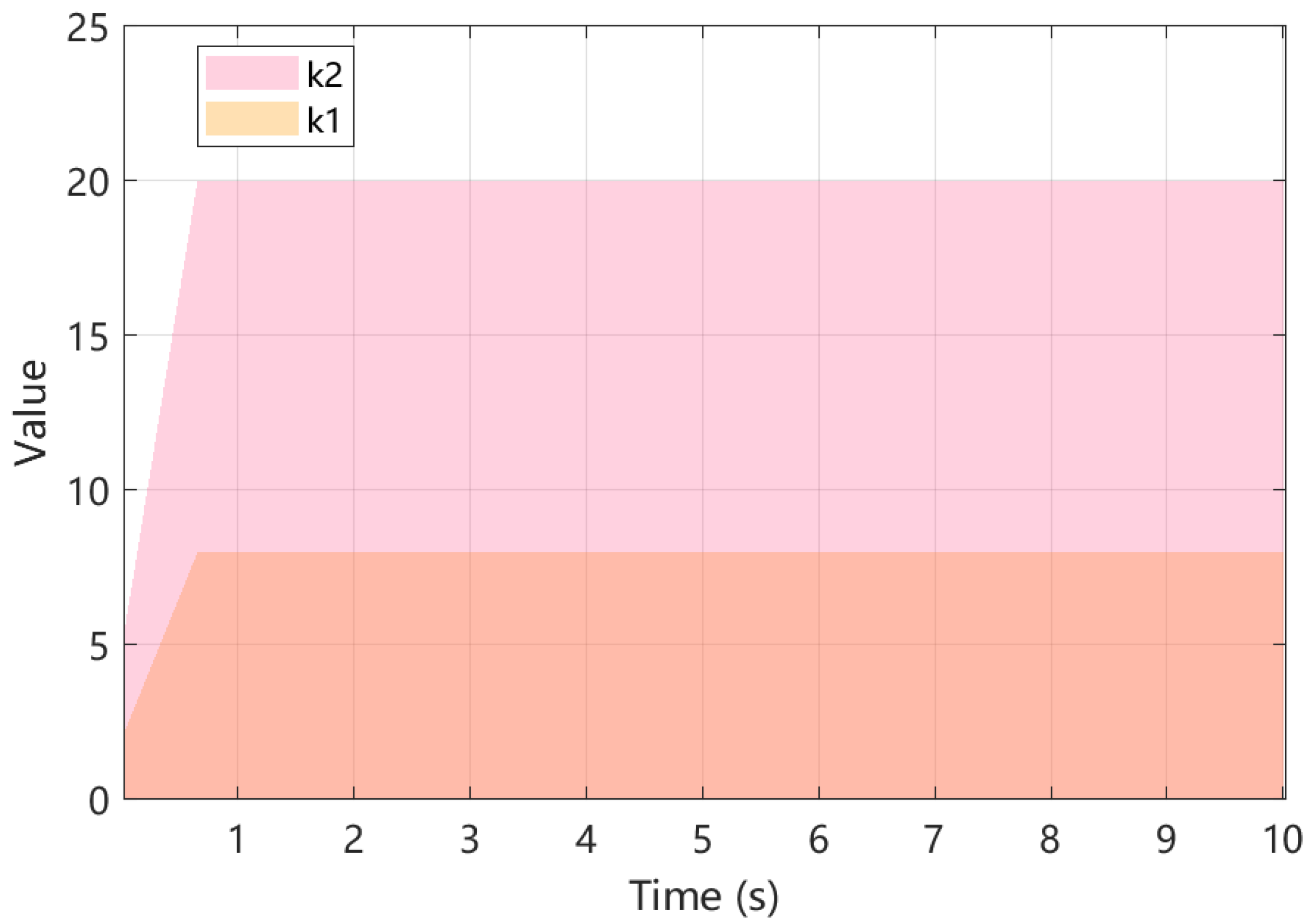
The tuning of proportional and integral parameters requires repeated experimental adjustments, which is time-consuming and heavily reliant on experience. If actual disturbances exceed preset limits or vary dynamically, fixed gains may cause system instability or performance degradation. To avoid time-consuming trial-and-error simulations and manual tuning, the following adaptive gain law is proposed:
The dynamic control of a hexarotor UAV relies on the quadratic relationship between motor speed and rotor thrust and counter-torque. By coordinating the nonlinear coupled outputs of the six motors, the spatial resultant force and three-axis aerodynamic moments are cooperatively controlled. The total vertical lift is maintained by the synchronous operation of symmetrically arranged motors, meeting the lift requirements for hovering and vertical ascent or descent. Pitch and roll moments are generated by differential control of paired motors, creating thrust gradients to facilitate attitude adjustment. Yaw moments are controlled via the torque differential between clockwise and counterclockwise rotating rotor groups. The resultant force, aerodynamic moments, and motor speeds of the hexarotor UAV satisfy the following relationships:
3.5. Proof of Lyapunov Stability and Finite-Time Convergence
3.5.1. Proof of Finite-Time Stability and Convergence for the Position Loop
To verify system stability and guarantee convergence of both the sliding surface and disturbance estimation errors to zero, the following Lyapunov function, incorporating sliding surface energy and disturbance estimation error, is constructed:
where
, its derivative is given by
To guarantee system stability,
should be positive definite and
should be negative semi-definite. From Equation (39), it follows that when
and
hold, then
. To ensure global asymptotic stability,
must be satisfied. Differentiating Equation (39) yields:
By substituting Equations (18)–(20) into (41), we obtain:
By reorganizing the nonlinear terms in Equation (42) and leveraging the element-wise sign-absolute value mapping property of the sign function, the above expression can be expressed as:
In the above equation, the last two terms are both negative. To ensure the derivative of the Lyapunov function is negative definite, the first term is treated with the Cauchy–Schwarz inequality, resulting in:
By substituting Equation (44) into Equation (43), we obtain:
Since
denotes the diagonal sliding gain matrix which must be set manually during simulations, parameters are chosen as
(
indicating the minimum element of the matrix),
, and there exists
such that
Based on the Lyapunov function:
From the above expression, we obtain:
assuming
, it follows that
By combining Equation (48), we obtain:
By substituting Equation (51) into Equation (48), we get:
Based on Lemma 1, the system converges in finite time.
3.5.2. Proof of Stability and Finite-Time Convergence for the Attitude Loop
To verify the stability of the system, the Lyapunov function is chosen as:
where
,
, and
,
, are ideal gains with
. From Equation (54), the chosen Lyapunov function is positive definite, and system stability requires
. Differentiating the Lyapunov function and substituting Equation (36) yields
Decompose the derivative terms of the Lyapunov function, expand and treat each term individually:
Control terms: leveraging vector properties:
and
, we obtain:
Integral terms: applying the Cauchy–Schwarz inequality yields:
Disturbance terms: by leveraging disturbance boundedness
and the Cauchy–Schwarz inequality, we get:
Gain error terms:
Combining Equations (56)–(60) yields:
When
: Since
stops increasing while
continues to adapt, it follows that:
By combining Equations (61) and (62), we obtain:
Given
, substitution into Equation (63) yields:
From Lemma 1, it follows that the system converges within finite time T.
5. Conclusions
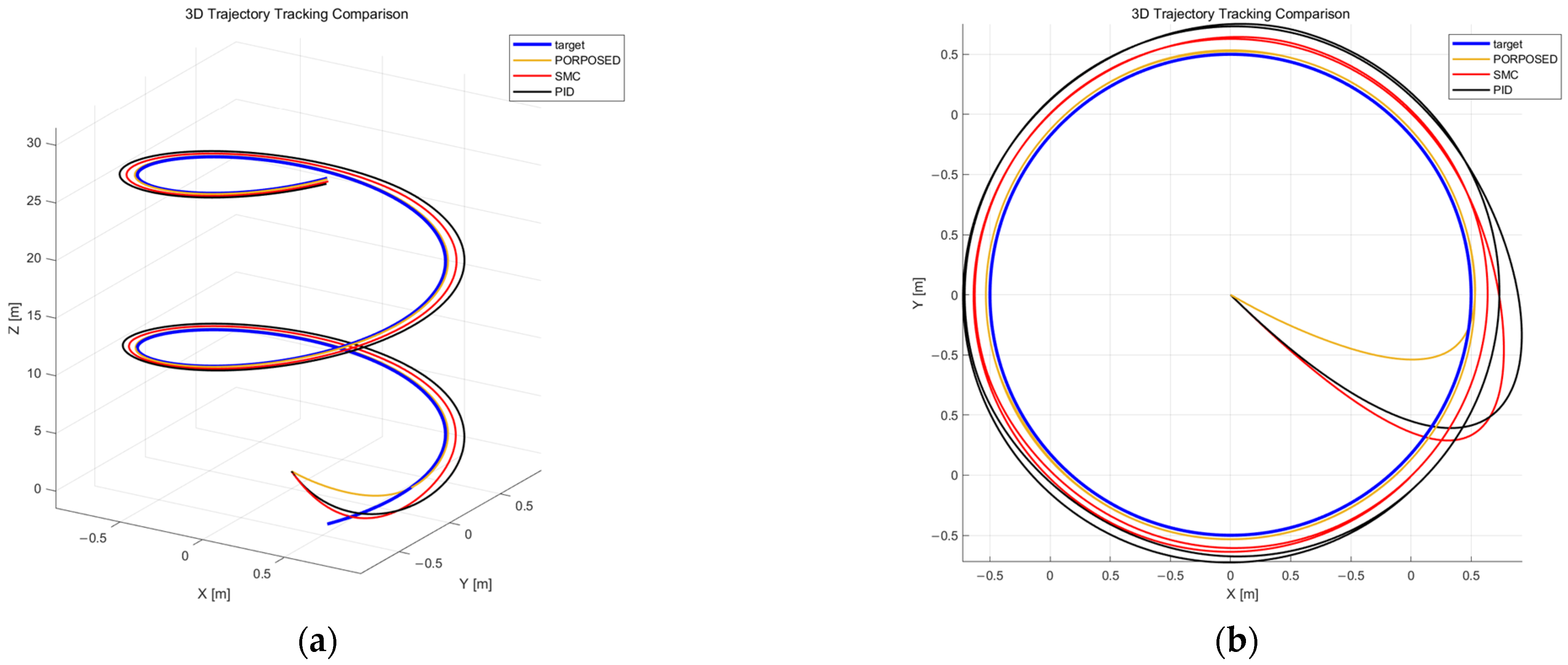
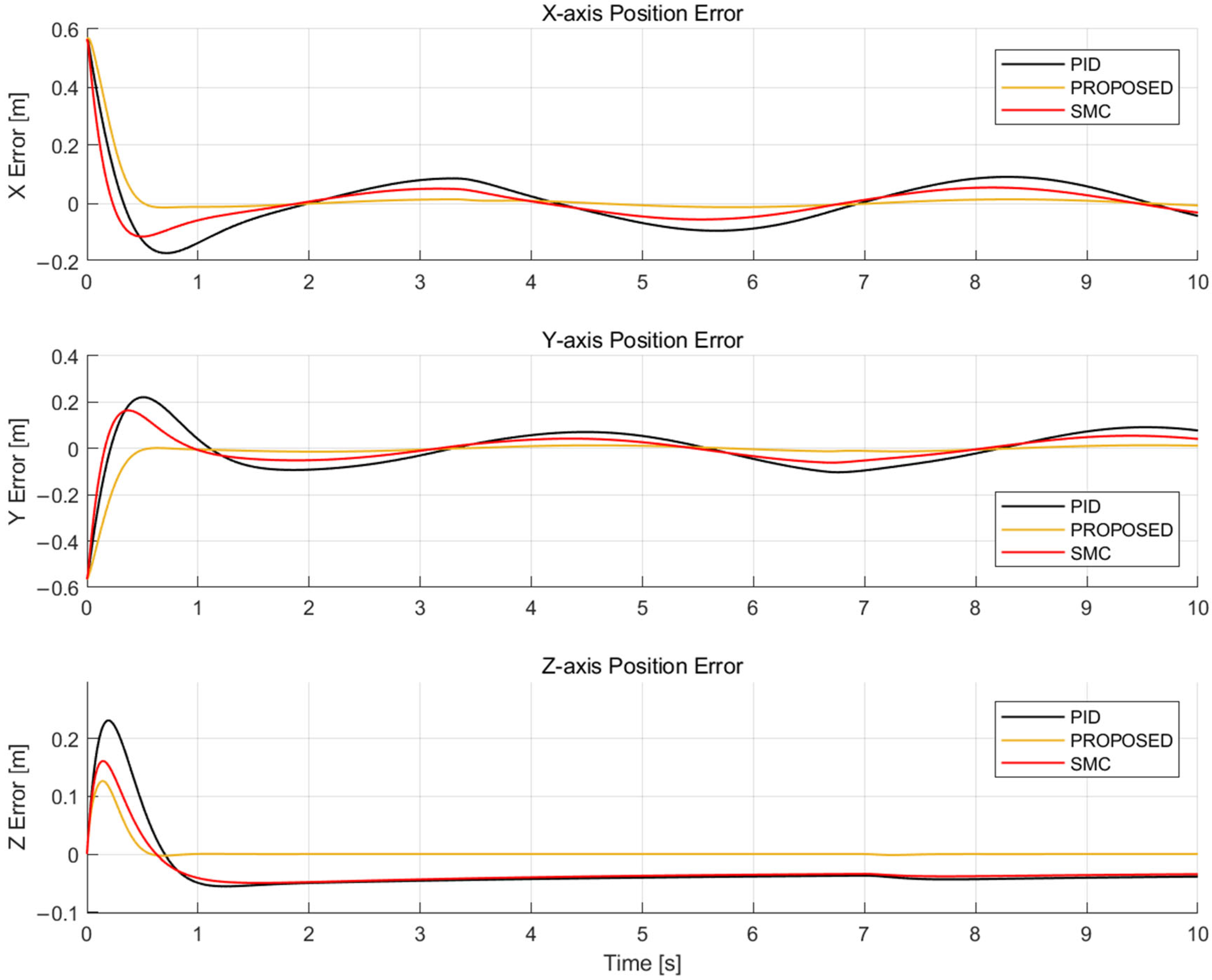
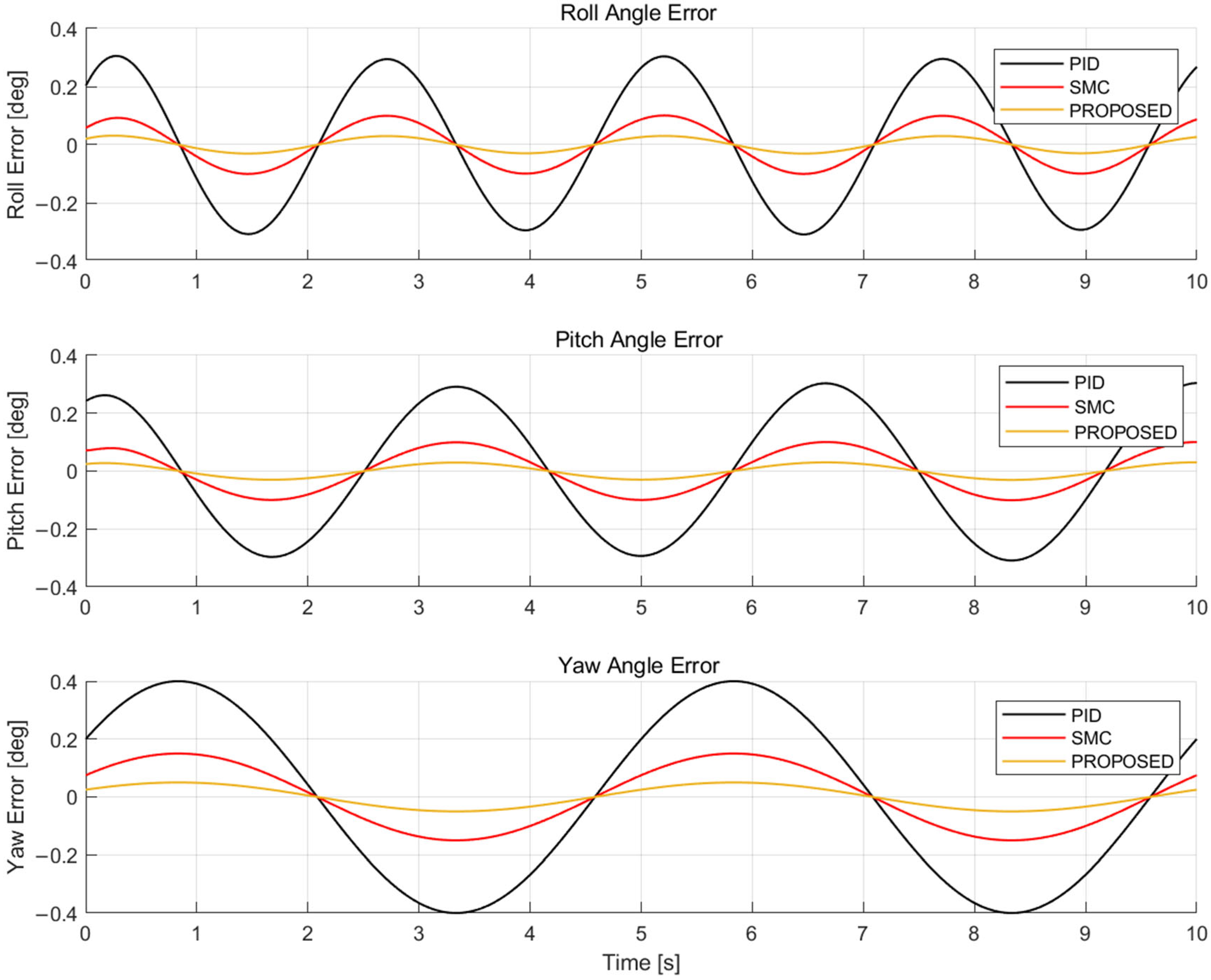
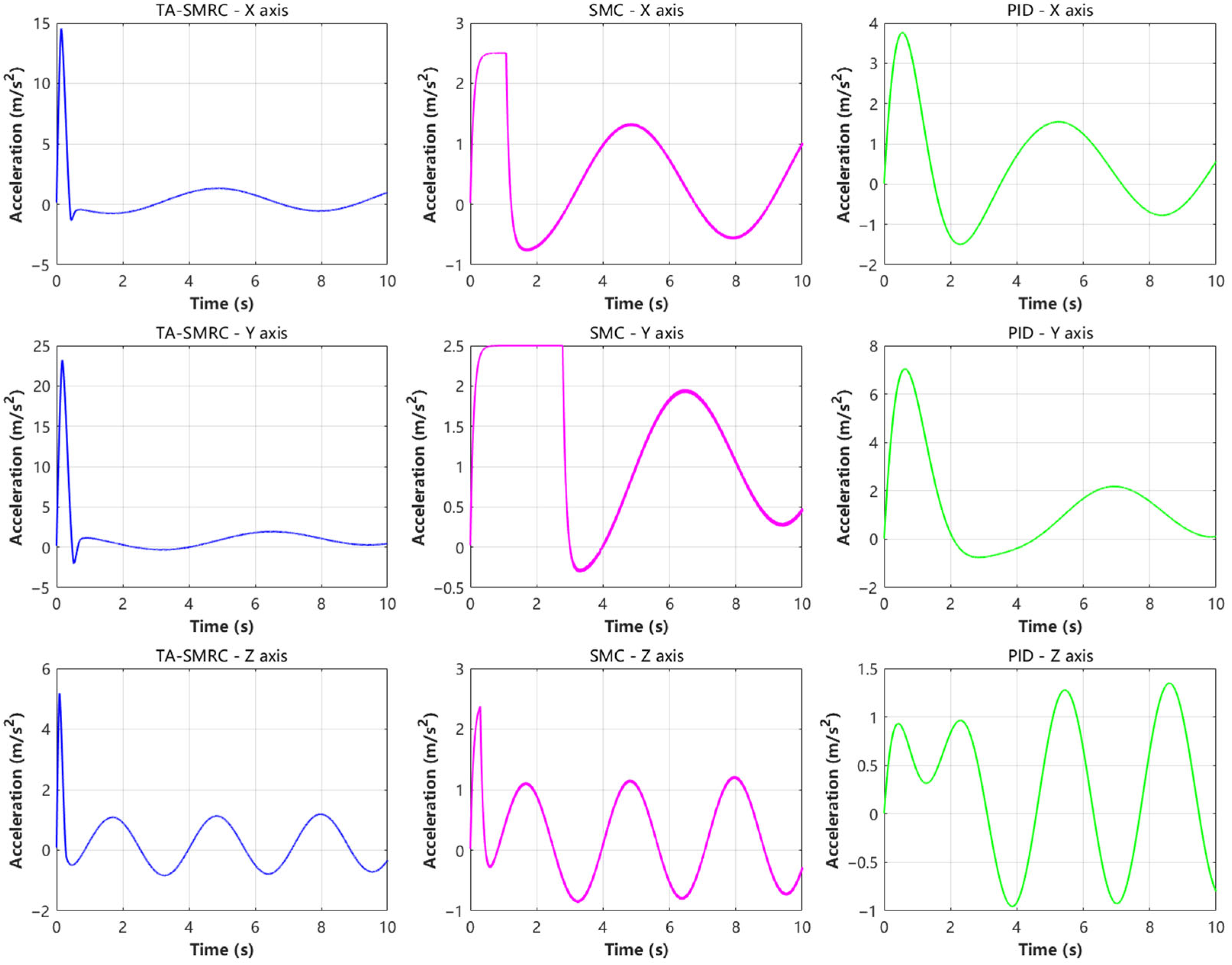
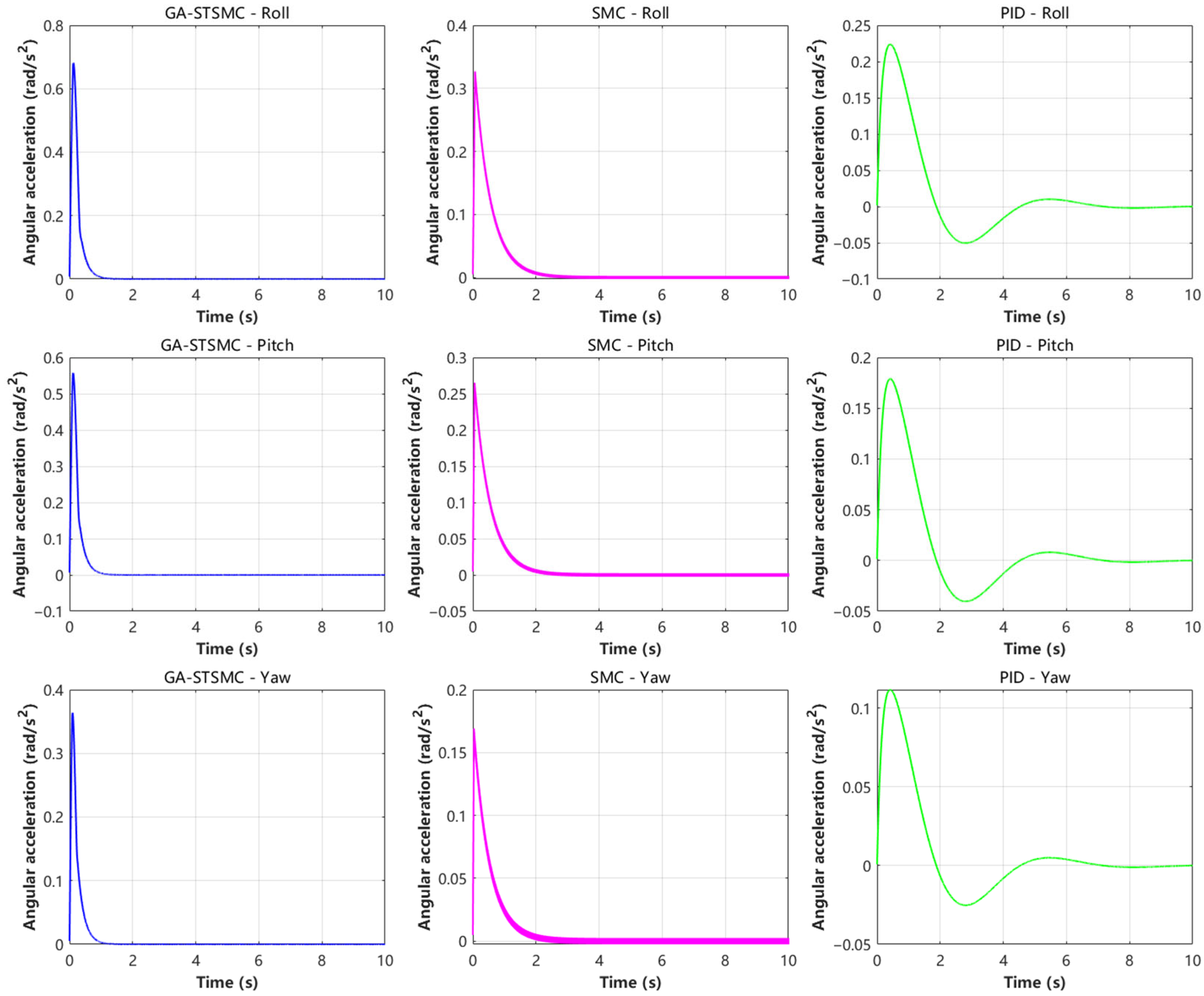
This paper addresses the issue of position and attitude stability control for hexarotor UAVs under external disturbances, proposing a hierarchical composite adaptive sliding mode control approach. A TSMRC is designed for the position loop, and an adaptive rate is introduced to estimate the external disturbances in the absence of interference. For attitude control, a STSMC is designed, with an adaptive rate introduced to adjust the sliding mode parameters in real-time. To validate the feasibility and advantages of this approach, a spiral trajectory tracking experiment was performed and compared with SMC and PID control. The experimental results indicate that the TA-SMRC controller can track the position command signal stably and accurately within 0.4 s, with the steady-state error consistently remaining within ±0.05 m under disturbance. In comparison to traditional sliding mode and PID control, it enhances the tracking speed, accuracy, and robustness. The GA-STSMC controller reaches the desired angle within 0.65 s, with the steady-state error consistently remaining within ±0.2°. The attitude channel control input reaches its peak in 0.18 s. In comparison to traditional sliding mode control and PID control, it exhibits faster dynamic response speed and enhanced stability. In conclusion, this composite control scheme shows significant advantages in dynamic tracking accuracy, steady-state robustness, and control smoothness.

