Abstract
Accurate modeling and performance analysis of brushless DC (BLDC) motors are essential for high-efficiency control in modern drive systems. In this article, a BLDC motor was modeled using system identification techniques. In addition, experimental data were collected from the BLDC motor, including its speed response to various input signals. Using system identification tools, particularly those provided by MATLAB/Simulink R2024b, an approximation model of the BLDC motor was constructed to represent the motor’s dynamic behavior. The identified model was experimentally validated using various input signals, demonstrating its accuracy and generalizability under different operating conditions. Additionally, a series of mechanical load tests was conducted using the AVL eddy-current dynamometer to evaluate performance under practical operating conditions. Fixed load torques were applied across a range of motor speeds, and multiple torque levels were tested to assess the motor’s dynamic response. Electrical power, mechanical power, and efficiency of the entire system were computed for each case to assess overall system performance. Moreover, the real-time state of charge (SOC) of Lithium-ion (Li-ion) battery was estimated using the Coulomb counting method to analyze the impact of Li-ion battery energy level on the BLDC motor efficiency. The study offers valuable insights into the motor’s dynamic and energetic behavior, forming a foundation for robust control design and real-time application development.
1. Introduction
Brushless DC (BLDC) motors have gained significant attention in recent years due to their high efficiency, compact size, and reliability, making them suitable for electric vehicles (EVs), drones, robotics, and industrial drive systems [1]. Accurate modeling of BLDC motors is essential for the development of effective control strategies, energy-efficient operation, and system integration. Traditional physics-based models, although useful, often fail to account for nonlinearities such as friction, dead zones, and load variations under dynamic operating conditions. In contrast, system identification (SI) techniques provide a data-driven approach to derive simplified yet accurate models using experimental input–output data, making them well suited for embedded and real-time applications [2]. A comprehensive dynamic characterization of BLDC motors must consider both variable-speed input conditions and fixed-load torque levels, which are representative of real-world operational scenarios. Additionally, performance evaluation under these conditions is crucial for validating model generalizability and for quantifying system efficiency. In battery-powered applications such as EVs, the performance of BLDC motors is closely influenced by the state of charge (SOC) of the Lithium-ion (Li-ion) battery, necessitating a unified experimental framework that integrates motor modeling, validation, load testing, and battery analysis.
Several studies have highlighted the effectiveness of MATLAB-based system identification in modeling BLDC motors. Khan et al. [3] demonstrated that linear and nonlinear models identified using least-squares (LS) and NARX methods achieved over 98% accuracy in replicating motor dynamics, supporting the reliability of data-driven modeling approaches. Similarly, Hat et al. [4] proposed a modeling approach for a BLDC motor using a pseudo-random binary sequence (PRBS) excitation and system identification techniques in MATLAB. The resulting transfer function model, with over 90% accuracy, was used to design a PID controller implemented on an Arduino Mega for real-time control. A data-driven framework was developed for modeling, characterizing, and identifying key parameters of permanent magnet DC (PMDC) motors. Abouseda et al. [5] experimentally identified the electrical and mechanical parameters of a BLDC motor using DC/AC tests and dynamometer measurements. The resulting transfer function model was validated in real time, demonstrating accurate dynamic representation suitable for control design. Pandya et al. [6] presented a comprehensive framework for modeling, characterization, and parameter identification of PMDC motors. Their approach integrated simulation and experimental data, applying nonlinear optimization techniques to estimate key motor parameters. The study reported strong agreement between identified models and measured responses, validating the methodology’s accuracy. Although focused on PMDC motors, the modeling and identification strategy is also applicable to BLDC systems, highlighting the broader importance of precise parameter estimation for accurate motor modeling and control in electric drive applications.
Recent advances in parameter identification of electric motors have led to the development of intelligent and hybrid estimation techniques aimed at improving dynamic accuracy and robustness. Su et al. [7] proposed a multiparameter identification framework for permanent magnet synchronous motors (PMSMs) using a model reference adaptive system (MRAS) combined with a simulated annealing particle swarm optimization (SA-PSO) algorithm, which demonstrated improved convergence and reduced error under dynamic conditions. Yang et al. [8] introduced an energy-based modeling approach for PMSM-driven belt conveyors and applied an online recursive least squares (RLS) identification algorithm, which effectively captured changes in inertia and friction parameters under varying operational scenarios. Additionally, Zhu et al. [9] provided an overview of online parameter estimation methods for PMSMs, highlighting techniques such as EKF, RLS, and learning-based models, and emphasizing the role of hybrid approaches for real-time performance and noise robustness. Moreover, Kerem [10] employed an adaptive-network-based fuzzy inference system (ANFIS) to estimate motor torque in electric vehicle applications, showing enhanced accuracy under uncertain and nonlinear conditions. These studies collectively highlight the growing trend toward intelligent system identification strategies that can be extended to BLDC motors for enhanced modeling and control performance.
Intelligent control techniques have also been widely explored to enhance the modeling and performance analysis of BLDC motor systems. Al Mashhadany et al. [11] developed a BLDC motor model integrated with various intelligent controllers, including fuzzy logic and artificial neural networks, and demonstrated their effectiveness in improving system stability and transient response under different operating conditions. Similarly, El Sawy et al. [12] investigated the dynamic behavior of brushless AC motors using different sensorless control schemes, highlighting the trade-offs between accuracy and computational complexity. These studies emphasize the relevance of intelligent and sensorless techniques in real-time control of brushless motors, and their findings can be extended to BLDC applications for robust modeling and improved performance under varying load and speed profiles.
A closed-loop subspace identification method based on auxiliary variables was proposed by Zhang et al. to accurately model a permanent magnet BLDC motor under noisy conditions. The technique was experimentally validated using a chassis dynamometer, demonstrating high robustness and reliability under practical operating scenarios [13]. Arifin et al. [14] employed a PRBS input combined with the N4SID subspace identification method to develop a dynamic model of an electric power steering motor. The identified model was validated using PI and PID controllers tuned via various methods, where the Haugen-tuned PI controller exhibited superior tracking performance. Although their study focused on EPS motors, the methodology and controller evaluation approach are directly relevant to BLDC motor modeling and control strategies. Additionally, Marcos-Andrade et al. [15] introduced an online algebraic estimation method for identifying key parameters and external disturbances in BLDC motors. Their approach enables real-time estimation of variables such as load torque and speed using input–output measurements without requiring persistent excitation. The method was validated experimentally and demonstrated effective performance under variable operating conditions, making it suitable for embedded control and fault detection applications. A recent study proposed a chaotic Gaussian–Cauchy Rao algorithm (CGCRAO) to enhance the accuracy and efficiency of parameter identification in PMSMs. The method incorporates chaotic initialization using a Tent map to improve population diversity and convergence speed, along with a hybrid mutation strategy based on Gaussian and Cauchy distributions to balance global and local search capabilities [16]. Although originally applied to PMSMs, the CGCRAO algorithm’s structure makes it adaptable for BLDC motor identification due to the similar dynamic and electrical characteristics of both motor types.
A least squares-based optimization method was developed for estimating key parameters of DC motors using experimentally acquired data. The approach utilized the LS-ARX algorithm and nonlinear least squares optimization to accurately determine electrical and mechanical parameters such as resistance, inductance, and inertia. The method demonstrated high model fidelity and robustness, outperforming conventional techniques in terms of parameter accuracy and fitting performance [17]. An improved dynamic forgetting-factor recursive least squares (FFRLS) algorithm for DC motor parameter identification was proposed, aiming to enhance the performance of traditional RLS methods. By designing an adaptive forgetting-factor adjustment function, the improved algorithm avoids initial fluctuations and directly initiates identification from a stable phase. It successfully estimates key motor parameters, including moment of inertia and viscous friction. Simulation results demonstrate that the improved FFRLS achieves faster convergence and stronger robustness against disturbances compared to standard RLS and FFRLS methods [18]. Rodríguez-Abreo et al. [19] introduced a novel metaheuristic technique for motor parameter identification that incorporates dynamic-response equations—from both transient and steady-state phases—as constraints in the optimization process. Implemented in three algorithms (Grey Wolf Optimizer, Jaya, and Cuckoo Search), this approach reduced the search space by linking some unknowns via dynamic relations. Tests on two motors with simulated and experimental data showed the enhanced methods achieved equivalent estimation accuracy while reducing iterations by 10–50%. Furthermore, Cortés-Romero et al. [20] employed RLS to estimate the electrical parameters of a BLDC motor from voltage and speed measurements. Their model was validated in real time using Simulink and effectively integrated into a PI controller for speed regulation. This study demonstrated the practicality of RLS-based approaches for adaptive applications.
Recent efforts have focused on improving the accuracy and reliability of SOC estimation in Li-ion batteries through enhanced Coulomb Counting techniques and hybrid algorithms. Wu et al. [21] proposed an improved Coulomb counting method with adaptive error correction (ICC-AEC), integrated within a dual closed-loop control structure for Li-ion battery SOC estimation. Their approach combines a first-order RC battery model with a forgetting-factor RLS algorithm to continuously recalibrate the initial SOC and battery capacity in real time. Validated under dynamic load profiles and varying temperatures, the method demonstrated superior accuracy and robustness compared to conventional mixed and closed-loop estimation techniques. Pu and Wang [22] developed a combined SOC estimation framework integrating a Long Short-Term Memory (LSTM) neural network with an Unscented Kalman Filter (UKF). Their method demonstrated high prediction accuracy and robustness against noise, benefiting applications with irregular current profiles. Similarly, Fahmy et al. [23] proposed a hybrid SOC estimation method for Li-ion batteries that combines Coulomb counting with an adaptive unscented Kalman filter (AUKF). Battery model parameters are identified using a state-space representation optimized via the African Vultures Optimizer (AVOA). The hybrid method was tested under varying temperatures and operating conditions using a 2.6 Ah Panasonic cell. Simulation results demonstrated that this approach outperforms existing hybrid methods by achieving the lowest estimation error across different scenarios.
The influence of mechanical load torque on motor behavior has been investigated in various experimental settings. Noval et al. [24] evaluated a chassis dynamometer for light EVs by analyzing the accuracy of torque and speed measurements. The study confirmed a consistent relationship between load torque and motor speed, with low measurement errors, demonstrating the dynamometer’s reliability for performance testing. However, few studies have combined fixed-torque testing with model validation using system identification frameworks.
Battery SOC estimation has also become a key focus in recent research. Coulomb counting remains the most widely used method due to its real-time compatibility, though it is susceptible to integration drift. Kunatsa et al. [25] reviewed SOC estimation techniques and emphasized the importance of accurate SOC tracking for optimizing system efficiency and prolonging battery life.
Despite significant advancements in each of these areas, there is a lack of comprehensive experimental studies that combine system identification-based modeling, load testing using dynamometers, and battery SOC impact analysis into a unified framework. Most prior works focus on one or two of these aspects in isolation, limiting the understanding of their interdependence in practical applications.
This study aims to address current research gaps by proposing a unified framework for modeling, dynamic performance analysis under mechanical load, and SOC-aware energy evaluation of BLDC motors. The motor’s dynamic behavior is identified and modeled through data-driven system identification techniques using PRBS excitation implemented in MATLAB. The resulting model is validated with diverse input signals beyond the training dataset to assess its generalization and robustness. Mechanical performance is experimentally evaluated using an AVL eddy-current dynamometer under various fixed torque and variable speed conditions. Additionally, real-time SOC estimation of the Li-ion battery is performed via the Coulomb counting method to examine the impact of battery energy levels on motor efficiency and operational performance. This integrated framework provides valuable insights to support the design of robust control strategies and optimize energy management in BLDC-based drive systems. The main contributions of this study are as follows:
- Development of a comprehensive experimental modeling framework for BLDC motors combining PRBS-based system identification and MATLAB tools to derive dynamic transfer function models.
- Experimental validation of the identified model using multiple excitation signals, including sinusoidal, exponential, ramp, and chirp waveforms, demonstrating strong generalization beyond the training data.
- Detailed torque speed performance characterization under fixed load torque conditions using an AVL eddy-current dynamometer, revealing load-dependent motor behavior and efficiency trends.
- Measurement and analysis of electrical input power, mechanical output power, and overall system efficiency across different operating conditions.
- Integration of real-time SOC estimation via Coulomb counting to evaluate how battery energy levels influence motor current draw and efficiency.
- Presentation of a methodology adaptable to other BLDC motors and electric drive systems through tuning of motor-specific parameters, facilitating broader application in EVs, robotics, and industrial automation.
2. Mathematical Modeling of BLDC Motor
The BLDC motor is an electromechanical energy conversion device whose dynamic behavior is governed by the interaction of electrical, magnetic, and mechanical subsystems. While this study primarily adopts a data-driven system identification approach for model development, it is essential to present the classical mathematical formulation of the BLDC motor. This provides a theoretical foundation for understanding the system’s internal structure and facilitates comparison with the experimentally identified model.
2.1. Electrical Subsystem
In a three-phase star-connected BLDC motor, the electrical dynamics of each phase can be described by Kirchhoff’s voltage law. Neglecting mutual inductance, the voltage equations for the a, b, and c phases are given as follows:
In the above equations, represent the stator phase voltages applied to the motor windings, expressed in volts (V), while denote the corresponding phase currents, measured in amperes (A). The parameters and refer to the phase resistance (Ω) and phase inductance (H), respectively, both assumed to be identical for all three phases due to the motor’s symmetrical construction. The terms correspond to the back electromotive forces (EMFs) generated in each phase, also expressed in volts (V), which are functions of the rotor position and angular velocity.
Under balanced operating conditions, the sum of the three phase currents satisfies the following equation:
This constraint simplifies analysis and is commonly assumed in symmetric motor configurations.
2.2. Back EMF Generation
The back EMF in each phase is generated as a result of the rotor’s motion relative to the stator magnetic field. In BLDC motors, the back EMF typically exhibits a trapezoidal waveform, and its magnitude is proportional to the rotor speed. The back EMF for each phase can be modeled as follows:
where denotes the back EMF constant, measured in volts-second per radian , while represents the rotor angular velocity in radians per second . The variable corresponds to the electrical rotor position, also expressed in radians . The function is a normalized trapezoidal waveform that depends on the electrical angle, typically ranging between −1 and +1, and reflects the back EMF shape of each motor phase.
These waveforms are a function of rotor position and reflect the geometry of the motor and stator winding configuration. Accurate modeling of is critical for advanced control applications.
2.3. Mechanical Subsystem
The mechanical dynamics of the BLDC motor are governed by Newton’s second law for rotational systems. The net torque applied to the rotor determines its angular acceleration and is expressed as follows:
In the mechanical dynamics equation of the BLDC motor, represents the moment of inertia of the rotor, expressed in , which quantifies the rotor’s resistance to changes in angular velocity. Parameter denotes the viscous friction coefficient in , accounting for energy losses due to frictional forces opposing motion. Additionally, is the developed electromagnetic torque in generated by the motor as a result of current flow and magnetic interaction. Finally, refers to the external load torque applied to the motor shaft, which opposes the motor’s rotation. This relationship describes the balance of torques acting on the rotor and governs its acceleration or deceleration under dynamic operating conditions.
The electromagnetic torque produced by the BLDC motor is directly related to the interaction between back EMFs and phase currents. It can be formulated as follows:
In many practical applications, torque is alternatively modeled using the torque constant , assuming ideal linearity, and is expressed as follows:
where is the equivalent or average line current and in is typically equal to in SI units when mechanical losses are neglected.
2.4. Remarks on Model Limitations and Data-Driven Approach
The above set of differential equations constitutes the conventional analytical model of a BLDC motor. While useful for control system design and theoretical analysis, such models require precise knowledge of several motor-specific parameters, including resistance, inductance, back EMF profiles, and rotor inertia. In practical scenarios, these parameters are often difficult to measure accurately or may vary due to changes in operating conditions such as temperature, load, or aging.
To address these challenges, this study incorporates a data-driven system identification approach. Rather than relying solely on fixed physical parameters, the dynamic behavior of the motor is captured through experimental measurements under realistic operating conditions. By applying excitation signals to the motor and recording the system’s response, empirical transfer function models are derived that reflect the actual system performance. This methodology allows for more adaptable and accurate modeling, especially in the context of control system design, where real-world performance often deviates from idealized models.
The data-driven model complements the theoretical formulation by providing a validated, input–output representation of the motor dynamics that accounts for nonlinearities, unmodeled effects, and parameter uncertainties. It enables the development of more robust control strategies and provides a foundation for further analysis under different load conditions.
The following section describes the identification methodology, signal design, validation process, and performance evaluation of the experimentally derived BLDC motor model under no-load conditions.
3. Materials and Methods
This section describes the hardware configuration, signal design, data acquisition process, and experimental procedures used for dynamic modeling and performance analysis of the BLDC motor. The methodology was structured to facilitate both system identification conditions and comprehensive performance evaluation under fixed load torque conditions with variable speed inputs.
3.1. Model Identification and Validation
The data-driven modeling of the 2.2 kW BLDC motor using system identification techniques is organized into a sequence of well-defined steps to ensure clarity and reproducibility:
- Modeling Objective: The main goal is to develop an accurate empirical model that captures the dynamic behavior of the BLDC motor under no-load conditions. This model serves as a foundation for performance analysis and future control design.
- Data Acquisition: PRBS signal is applied as excitation input to the motor through a real-time interface. The corresponding output speed responses are recorded using the Kelly controller.
- Model Structure Selection: Using the System Identification Toolbox in MATLAB, different linear transfer function structures are explored to represent the input–output relationship of the system.
- Model Parameter Estimation: The model parameters are estimated based on a prediction-error minimization algorithm using least-squares fitting techniques.
- Model Validation and Performance Analysis: The BLDC motor model was identified using input and output data obtained under PRBS excitation. To evaluate the model’s ability to generalize beyond the identification dataset, various independent test signals, such as sinusoidal, exponential, ramp, and chirp waveforms, were applied experimentally to the physical system and to the identified model in MATLAB Simulink. The simulated responses were then compared with the corresponding experimental results to qualitatively assess the accuracy of the model across a range of dynamic operating conditions.
This structured methodology ensures a systematic representation of the motor’s dynamic characteristics based on experimental data.
3.2. Experimental Setup
The experimental platform was developed around a three-phase 2.2 kW BLDC motor, controlled via a Kelly KLS12301-8080I controller (Kelly Controller Inc., Shanghai, China). The motor was mechanically coupled to an AVL eddy-current dynamometer (AVL List GmbH, Graz, Austria), capable of applying precise, programmable load torques while simultaneously measuring shaft speed and torque with high accuracy. The experimental configuration is depicted in Figure 1, and the main technical specifications of the BLDC motor are listed in Table 1.
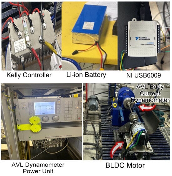
Figure 1.
Experimental setup of components used for BLDC motor testing.

Table 1.
Specifications of the BLDC motor used in this study.
3.3. Signal Design and Data Acquisition
To evaluate the dynamic response of the BLDC motor under open-loop conditions, a set of voltage input signals was generated using MATLAB/Simulink and transmitted to the analog input of the Kelly KLS12301-8080I controller via an NI USB-6009 data acquisition (DAQ) device (National Instruments, Austin, TX, USA). These signals modulated the duty cycle of the motor drive, enabling precise control of motor speed. Five distinct excitation waveforms were employed to stimulate the system across a wide range of dynamic behaviors:
- Sinusoidal signal was applied to evaluate the frequency response characteristics of the system.
- Exponentially rising signal was used to replicate smooth acceleration profiles.
- Chirp signal was employed to excite the system across a continuously varying frequency range.
- Ramp signal was utilized to analyze the system’s response to linearly increasing inputs and to detect any lag or rate limitations.
- PRBS signal was introduced to provide broadband excitation for system identification, enabling accurate modeling across a wide frequency spectrum.
Each excitation waveform was carefully generated in MATLAB and applied in real time using Simulink’s analog output blocks connected to the NI USB-6009 data acquisition device. The corresponding motor speed responses were measured using a Hall-effect sensor and recorded in MATLAB for subsequent offline analysis.
All tests in this phase were conducted under no-load conditions to isolate the motor’s inherent electrical and mechanical dynamics, free from external resistive torques. Although the BLDC motor was mechanically coupled to an AVL eddy current dynamometer (operated in passive mode), no active loading was applied during this stage. The resulting input–output datasets were subsequently used for system identification and model validation, as detailed in the following section.
3.4. System Identification Procedure
The acquired datasets were directly used in MATLAB’s System Identification Toolbox to derive an empirical model representing the input–output dynamics of the BLDC motor. No preprocessing, such as offset removal, detrending, or filtering, was applied to the raw data to preserve the original system behavior during model estimation.
The transfer function of the BLDC motor was evaluated to obtain a simplified, continuous-time representation of its input–output behavior. This approach enables the characterization of key dynamic properties such as gain, time constants, and system order, and provides a foundation for designing classical control strategies. Moreover, the transfer function model facilitates validation by comparing its simulated response to experimental speed data under various test inputs.
Multiple excitation signals were assessed to determine the most suitable input for system identification. A separate transfer function was estimated for each signal type, and the resulting models were compared based on their ability to generalize to other test conditions. The excitation signal that yielded the most accurate and consistent model performance across different input scenarios was selected for use in the final identification and validation process.
3.5. Load Testing Procedure: Torque–Speed Characterization
To evaluate the performance of the BLDC motor under realistic loading conditions, a series of controlled mechanical load tests was conducted using an AVL eddy-current dynamometer. The objective was to assess the motor’s behavior under varying speeds at fixed load torques and to quantify its efficiency across different operating points. The test methodology involved applying a variable reference speed at several discrete torque levels. Specifically, the dynamometer applied constant torque values ranging from 0 to 4 . For each fixed torque level, the motor was driven through a speed range from 0 to approximately 2900 rpm, allowing for detailed characterization of its dynamic and steady-state performance. The Kelly KLS12301-8080I controller regulated the motor speed via analog input, while the programmable torque was applied through the dynamometer.
During each test run, the terminal voltage and current of the Li-ion battery, along with the rotational speed of the BLDC motor, were monitored using the Kelly controller and logged in real time via a custom Python 3.12 script over RS232 communication.
This procedure enabled high-resolution mapping of the torque–speed relationship and provided the necessary data to compute electrical input power, mechanical output power, system efficiency, and SOC. The data collected was used in the subsequent analysis to evaluate performance trends and identify operating regions with optimal energy efficiency.
4. Electrical and Mechanical Power Analysis, Efficiency Assessment, and SOC Estimation
To assess the performance of the BLDC motor and the associated battery system, both energy efficiency and the SOC of the Li-ion battery were evaluated based on the data collected during load testing. The analysis was conducted using the electrical and mechanical measurements obtained under fixed torque levels with varying reference speed conditions, as described in the previous section.
4.1. Efficiency Calculation
The BLDC motor’s efficiency was determined by comparing the mechanical output power to the electrical input power at each operating point. The electrical input power was calculated as follows:
where is the battery terminal voltage and is the discharge current, both measured through the Kelly controller.
The mechanical output power was computed using the measured shaft torque and angular speed , obtained from the AVL eddy-current dynamometer and Kelly controller, respectively. Angular speed was derived from the motor’s rotational speed as follows:
The overall efficiency of the entire system was then calculated using Equation (12):
Efficiency was evaluated across all combinations of fixed torque levels and variable speeds, enabling a detailed analysis of the system’s operating characteristics and energy conversion behavior.
4.2. SOC Estimation
The SOC of the Li-ion battery was estimated using the Coulomb counting method, which integrates the discharge current over time to track charge depletion. The SOC at a given time was calculated as follows:
where is the initial state of charge, is the nominal battery capacity (in ampere-hours), and is the discharge current (in amperes). The integration was performed numerically using the logged current data sampled during testing [26].
This combined analysis enabled a comprehensive evaluation of the system’s energy performance, supporting the identification of optimal operating points for torque–speed control and battery utilization.
5. Results and Discussion
This section presents the results of system identification, model validation, and experimental load testing of the BLDC motor. The accuracy of the identified transfer function model is evaluated, and the motor’s performance is analyzed under fixed load torque levels with variable speed inputs. In addition, the system’s electrical and mechanical efficiencies are examined.
5.1. System Identification Results and Model Validation
The dynamic characteristics of the BLDC motor were identified using a continuous-time transfer function derived from experimentally acquired input and output data. To evaluate the system’s response under a range of conditions, various excitation signals, including PRBS, sinusoidal, exponential, ramp, and chirp waveforms, were applied. Each excitation signal was evaluated based on its ability to generate a model that generalizes well across different operating conditions. Among them, the transfer function estimated using the PRBS signal demonstrated the highest accuracy and consistency in terms of generalization. Figure 2 shows the waveform of the PRBS signal used for identification.
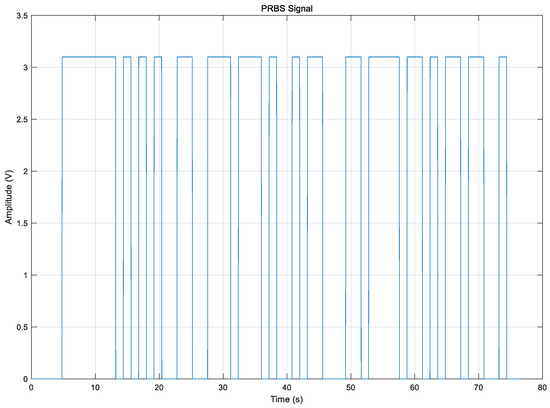
Figure 2.
PRBS signal used for identification.
The transfer function model of the BLDC motor was identified using experimental data obtained from PRBS signal excitation. The resulting model achieved a normalized root mean square error (NRMSE) of approximately 85.38%, indicating strong agreement between the simulated and measured behavior. The final transfer function is presented in Equation (14):
The transfer function in Equation (14) was obtained using MATLAB’s System Identification Toolbox (ident) by fitting a linear model structure to experimental voltage (input) and rotational speed (output) data of the BLDC motor. This data-driven approach eliminates the need to derive physical parameters directly, instead producing a compact, experimentally validated model that reflects the motor’s dynamics. Although the model is expressed in the Laplace domain, it corresponds to the following time-domain third-order differential equation, as follows:
where is the motor’s angular speed and is the input voltage. This representation captures both the dynamic and steady-state behavior of the BLDC motor system and is used throughout this study for performance evaluation and simulation.
Moreover, to evaluate its generalization capability, the identified model was validated against experimental results obtained using other excitation signals, such as sinusoidal, exponential, ramp, and chirp signals. Figure 3 illustrates the MATLAB/Simulink model used for the validation of the identified BLDC motor model. In addition, a dead zone nonlinearity was incorporated into the BLDC motor model using the Dead Zone block in Simulink to account for the threshold input voltage below which the motor does not respond. This behavior reflects the real characteristics of the motor, which requires a minimum input of approximately 1.1412 volts to overcome internal friction and control delays. As shown in Figure 4, this improves the model’s accuracy, particularly in the low-input region.
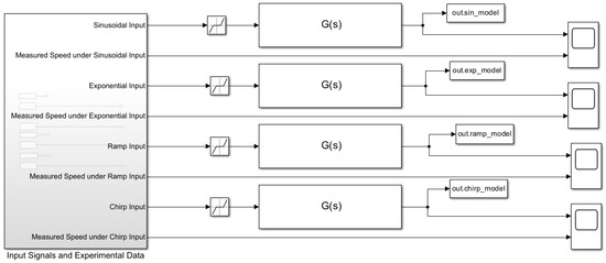
Figure 3.
MATLAB/Simulink model used for validation of the identified BLDC motor model.
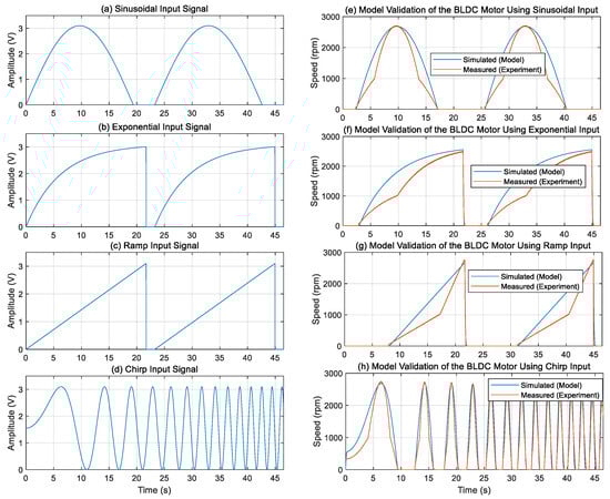
Figure 4.
Model validation under different excitation signals. (a–d): Input signals applied to the BLDC motor. (e–h): Corresponding measured and simulated speed responses.
Figure 4 shows the validation of the identified BLDC motor model using several excitation signals to evaluate its ability to generalize beyond the PRBS identification dataset. The input waveforms, including sinusoidal, exponential, ramp, and chirp signals, were generated in MATLAB Simulink and applied experimentally to the motor through the NI USB 6009 data acquisition device. The measured speed responses were compared with the simulated outputs from the transfer function model identified using the PRBS excitation.
Figure 4e highlights the response to the sinusoidal input, demonstrating excellent agreement between the simulated and experimental speed profiles. The simulation closely follows the periodic behavior of the motor speed, with minimal phase delay and amplitude deviation over the tested frequency range. These results confirm the model’s capability to accurately capture the motor’s oscillatory dynamics and validate its applicability to scenarios involving sinusoidal or cyclic speed inputs.
Figure 4f illustrates the system behavior under exponential excitation, which simulates smooth acceleration profiles commonly encountered in practical motor control scenarios. The identified model effectively reproduces the gradual increase in motor speed observed experimentally, particularly during the initial phase where acceleration is most prominent. Minor deviations near steady state likely stem from unmodeled nonlinearities or measurement noise; however, the overall close alignment validates the model’s capability to represent time-varying inputs with slow dynamics.
Figure 4g depicts the motor response to a ramp input, representing a linearly increasing speed reference. The model captures the general linear trend and steady-state speed with reasonable accuracy. The observed discrepancies during initial acceleration and transient transitions highlight limitations due to unmodeled effects such as frictional variations or controller nonlinearities. These findings emphasize areas for potential model refinement while confirming the model’s utility in approximating linear speed trajectories.
Figure 4h shows the validation under chirp excitation, where the input frequency continuously varies over time, testing the model’s dynamic fidelity across a broad frequency spectrum. The model successfully tracks both low-frequency and high-frequency oscillations in the motor speed, demonstrating its robustness in capturing complex frequency-dependent dynamics. This validation provides strong evidence that the model can be reliably used for control design tasks involving varying operating conditions.
Collectively, these results demonstrate that the PRBS-identified model generalizes well to diverse input signals, capturing key dynamic behaviors essential for practical BLDC motor applications. The close correspondence between simulation and experiment across different excitation types confirms the model’s accuracy and reliability, supporting its use for advanced control development, performance analysis, and real-time system implementation.
5.2. Torque–Speed Performance Under Load
Figure 5 illustrates the BLDC motor’s open-loop speed response under varying reference speed profiles and fixed mechanical load torques ranging from 1 to 4 N·m. In each subplot, a stepwise speed input signal ramping from 0 to approximately 2900 rpm was sent to the BLDC motor via the Kelly controller. The actual motor speed was measured experimentally to assess how the system responds to changes in demand under different load conditions.
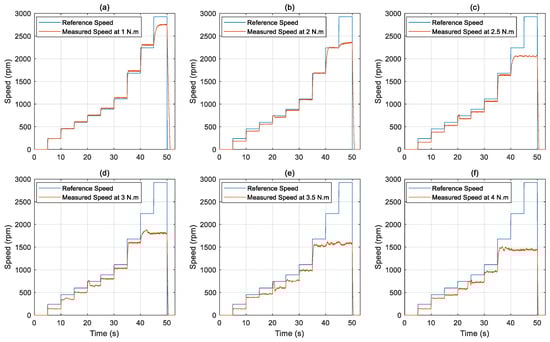
Figure 5.
Reference and measured speed responses of the BLDC motor under fixed load torques: (a) 1 N·m, (b) 2 N·m, (c) 2.5 N·m, (d) 3 N·m, (e) 3.5 N·m, (f) 4 N·m.
At a 1 N·m load torque, as shown in Figure 5a, the motor speed closely follows the reference input across the entire operating range, with minimal lag and deviation, indicating that the system behaves linearly and predictably under light mechanical loading. The measured speed rises steadily in response to each step without significant overshoot or oscillation. Similarly, in Figure 5b (2 N·m load), the motor still responds well to the increasing speed input, though minor delays become noticeable during transitions. These slight discrepancies suggest a growing influence of mechanical resistance on the system’s dynamic response.
As the load increases to 2.5 N·m, as shown in Figure 5c, the response begins to show more visible lag, particularly at higher reference speeds. The motor exhibits slower acceleration and reduced peak speed compared to the commanded profile, indicating the onset of torque-related performance limitations.
In Figure 5d, with a load of 3 N·m, under-speed behavior becomes more pronounced. The motor fails to reach the highest reference levels within the same timeframe, reflecting the combined effects of increased back EMF and current limitations that hinder performance at elevated speeds under load.
At 3.5 N·m and 4 N·m, the impact of mechanical loading becomes critical, as illustrated in Figure 5e and Figure 5f, respectively. The motor’s actual speed significantly diverges from the reference speed, particularly in the upper speed ranges. This reduced responsiveness likely results from the system reaching its voltage and current delivery limits, coupled with intensified back EMF effects and the finite torque capacity of the motor-driver setup.
These observations confirm that the BLDC motor and Kelly controller combination maintains acceptable performance under light to moderate load conditions. However, as mechanical torque increases, the system exhibits reduced responsiveness, especially during rapid acceleration or high-speed operation. These trends highlight the importance of accounting for load-dependent behavior in performance analysis and in the design of future closed-loop control strategies or hardware selection for high-demand applications.
Figure 6 presents the variation in battery terminal voltage of the Li-ion battery under different mechanical load torque conditions during speed ramp tests. The results reveal a distinct correlation between load torque and voltage behavior, providing critical insight into the battery’s dynamic response under varying operating conditions. At lower torque levels, such as 1 and 2 N·m (Figure 6a,b), the terminal voltage remains relatively stable across the full speed range, with only minor fluctuations during acceleration phases. This stability reflects lower current demands and reduced internal losses within the battery under light loading conditions.
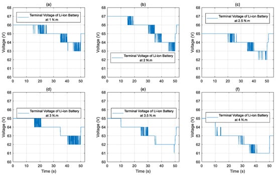
Figure 6.
Terminal voltage of the Li-ion battery during BLDC motor operation under variable reference speed and fixed load torque conditions: (a) 1 N·m, (b) 2 N·m, (c) 2.5 N·m, (d) 3 N·m, (e) 3.5 N·m, (f) 4 N·m.
As the torque demand increases, the voltage profile begins to exhibit more pronounced and sustained drops. In Figure 6c,d, corresponding to 2.5 and 3 N·m, transient voltage dips become apparent during acceleration intervals, indicating elevated current draw due to the increased mechanical load. The most significant effects are observed at the highest torque levels of 3.5 and 4 N·m (Figure 6e,f), where the terminal voltage declines below 62 V during high-speed operation. These voltage reductions are not only deeper but also more sustained, pointing to the increased electrical stress placed on the battery. This behavior is primarily attributed to the internal resistance of the battery and its interaction with the peak current demands during rapid speed changes.
The results underscore the importance of incorporating battery dynamics into system-level modeling and design. The observed sensitivity of voltage behavior to mechanical load conditions highlights potential limitations in high-demand scenarios and the need for effective energy management strategies. Such considerations are essential in BLDC motor drive applications, particularly where performance, efficiency, and reliability must be maintained under varying load conditions.
Figure 7 illustrates the variation in battery current drawn by the BLDC motor under variable speed conditions and fixed mechanical load torques ranging from 1 to 4 N·m. The results clearly demonstrate that battery current increases with both the applied torque and motor speed, highlighting the dynamic electrical demand placed on the power supply during different loading scenarios.
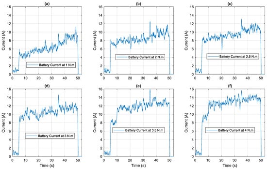
Figure 7.
Li-ion battery current under variable reference speed and fixed load torque conditions: (a) 1 N·m, (b) 2 N·m, (c) 2.5 N·m, (d) 3 N·m, (e) 3.5 N·m, (f) 4 N·m.
At lower torque levels (Figure 7a,b), the current profiles exhibit a gradual increase in magnitude as the speed ramps up, with only minor fluctuations. This behavior reflects stable operation with low energy consumption and minimal stress on the power supply. As the torque increases (Figure 7c–e), the current traces reveal a noticeable elevation in both average current and peak values, particularly during acceleration phases. The transient oscillations observed are indicative of the motor’s effort to overcome higher mechanical resistance and maintain speed tracking.
At the highest load torque of 4 N·m (Figure 7f), the battery current peaks at approximately 15 A, indicating the system’s maximum electrical load during the test sequence. The sharper current spikes and increased variability further suggest that the drive system is operating near its performance boundaries under this condition. These observations underscore the significant influence of mechanical load on current demand, which directly impacts system efficiency, battery heating, and overall energy management.
Overall, the results from Figure 7 reinforce the need for careful coordination between torque–speed profiles and power delivery capabilities. Effective control and thermal management strategies become increasingly critical at higher loads to ensure system reliability, protect battery health, and optimize energy utilization in BLDC motor drive systems.
Figure 8 presents the electrical input power characteristics of the BLDC motor during variable-speed operation under fixed mechanical load torque conditions. The input power was computed using real-time measurements of terminal voltage and current of the Li-ion battery, obtained via the Kelly controller’s RS232 interface and processed through a Python-based acquisition system. This analysis enables a comprehensive evaluation of the system’s energy demand in response to varying torque and speed levels.
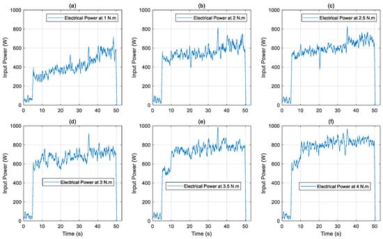
Figure 8.
Electrical input power of the BLDC motor under variable reference speed and fixed load torque conditions: (a) 1 N·m, (b) 2 N·m, (c) 2.5 N·m, (d) 3 N·m, (e) 3.5 N·m, (f) 4 N·m.
At a low load torque of 1 N·m (Figure 8a), the electrical input power increases gradually with speed, remaining below 650 W throughout the operating range. This relatively modest power consumption reflects reduced current draw and low mechanical resistance, leading to efficient motor operation. As the torque increases to 2 N·m and 2.5 N·m (Figure 8b,c), the power demand rises more steeply, with peak values nearing 780 W. This trend is consistent with increased electrical loading needed to sustain the desired speed under greater mechanical resistance.
At higher torque levels of 3 N·m, 3.5 N·m, and 4 N·m (Figure 8d–f), the input power exceeds 850 W during the higher-speed segments, revealing a significant escalation in energy consumption. These operating points represent more strenuous loading conditions, where both the current demand and the back EMF effects increase, thereby amplifying the required input power. Minor fluctuations in the power signal are particularly evident during acceleration phases and are attributed to transient current surges as the motor responds to changes in speed and load.
The results confirm a strong nonlinear dependency of electrical input power on both mechanical torque and speed. As the torque increases, the electrical efficiency of the system tends to decline due to elevated current demand and associated internal losses. These findings highlight the importance of integrating power analysis into motor control and energy management strategies, particularly for applications where sustained operation at high torque and speed is required. The power trends presented in Figure 8 provide a critical foundation for assessing the overall performance and efficiency of BLDC motor drive systems under realistic operational constraints.
Figure 9 presents the mechanical output power of the BLDC motor under variable speed operation and fixed load torque levels ranging from 1 to 4 N·m. The mechanical power was computed in real time as the product of the measured angular speed and the applied torque. The results demonstrate a clear dependency of mechanical power on both speed and torque, with a generally linear trend as expected from fundamental electromechanical principles.
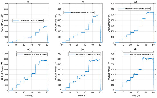
Figure 9.
Mechanical output power of the BLDC motor under variable reference speed and fixed load torque conditions: (a) 1 N·m, (b) 2 N·m, (c) 2.5 N·m, (d) 3 N·m, (e) 3.5 N·m, (f) 4 N·m.
In Figure 9a, at a load torque of 1 N·m, the mechanical power increases incrementally with each step in reference speed, reaching a peak value of approximately 280 W. The power trace is smooth and consistent, reflecting stable system operation under light loading. As the load torque increases to 2 N·m and 2.5 N·m in Figure 9b,c, the mechanical power output correspondingly rises, peaking at around 480 W and 550 W, respectively. While the profiles remain generally linear, slight ripples are observed during acceleration phases, attributable to minor transient deviations in motor speed and torque application.
At higher load torque levels, specifically 3 N·m, 3.5 N·m, and 4 N·m, as shown in Figure 9d–f, the mechanical power continues to increase, with values exceeding 600 W at higher speeds. However, the fluctuations in the measured power signals become more noticeable at these load conditions. These variations are primarily driven by the dynamic response of the motor and increased difficulty in maintaining speed regulation under higher torque demands. The fluctuations also reflect the system’s response to elevated current draw and associated back EMF and voltage drop effects, which slightly impact the consistency of power delivery during rapid speed changes.
Overall, the results in Figure 9 confirm that the BLDC motor is capable of delivering progressively higher mechanical power as load torque and speed increase, while also highlighting the onset of dynamic effects under heavier loading. The consistency and scalability of power output validate both the reliability of the experimental setup and the accuracy of the measurement methodology. Furthermore, the increasing signal fluctuations at higher torques underscore the importance of incorporating load-dependent performance characteristics into motor control design and system-level energy optimization strategies.
Figure 10 presents the efficiency profiles of the system, comprising the Li-ion battery, power electronics, and BLDC motor under variable speed conditions and fixed mechanical load torques ranging from 1 to 4 N·m. The results indicate a strong dependence of system efficiency on both load torque and operating speed, revealing distinct trends in the motor’s electro-mechanical energy conversion performance.
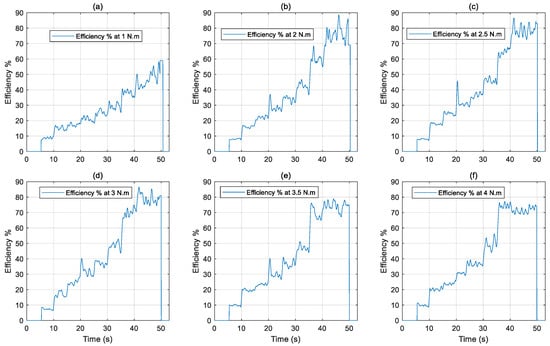
Figure 10.
Overall efficiency of the system under variable reference speed and fixed load torque conditions: (a) 1 N·m, (b) 2 N·m, (c) 2.5 N·m, (d) 3 N·m, (e) 3.5 N·m, (f) 4 N·m.
At a low load torque of 1 N·m (Figure 10a), the system exhibits a gradual increase in efficiency with speed, peaking at approximately 57% during high-speed operation. This relatively modest efficiency can be attributed to the mismatch between the electrical input power and the low mechanical output power, resulting in a higher proportion of losses, particularly at lower operating points.
As the torque increases to 2 N·m and 2.5 N·m (Figure 10b,c), the efficiency improves significantly, reaching peak values of 86% and 83%, respectively. This enhancement reflects a more favorable load condition where the motor operates closer to its optimal efficiency region, with reduced relative losses and better utilization of the supplied electrical energy.
Under heavier load conditions of 3 N·m and 3.5 N·m (Figure 10d,e), the motor continues to demonstrate strong performance, achieving peak efficiencies of around 86% and 78% within the system under tested conditions. Although the efficiency remains high, slight reductions are observed, particularly at higher speeds, likely due to increased current-induced losses and potential thermal effects.
At the maximum tested load of 4 N·m (Figure 10f), the motor sustains a system efficiency above 70% across most of the operating range. The relatively stable efficiency profile under this high torque level underscores the motor’s robustness and its capacity to maintain effective energy conversion despite elevated electrical and thermal stress.
These experimental findings confirm that the BLDC motor achieves optimal efficiency under moderate to moderately high torque conditions, where electrical input and mechanical output are better matched. However, at both very low and very high torque levels, efficiency tends to decline due to inherent system losses and thermal limitations. This analysis emphasizes the importance of operating the motor within its optimal torque–speed envelope to maximize performance and energy efficiency in real-world applications.
Figure 11 presents the estimated SOC of the Li-ion battery during variable-speed operation under six different fixed torque levels. These results provide valuable insight into how mechanical loading influences battery depletion dynamics over short operational intervals.
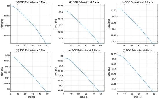
Figure 11.
SOC estimation of the Li-ion battery during variable speed operation of the BLDC motor under different fixed load torque levels: (a) 1 N·m, (b) 2 N·m, (c) 2.5 N·m, (d) 3 N·m, (e) 3.5 N·m, (f) 4 N·m.
At the lowest load condition of 1 N·m (Figure 11a), the SOC exhibits a slow and nearly linear decline, falling from approximately 99% to 98.81%. This behavior reflects low current draw, minimal internal losses, and stable energy consumption during light-duty operation. The system operates efficiently under these conditions, with negligible stress imposed on the battery.
As the load torque increases to 2 N·m and 2.5 N·m (Figure 11b,c), the SOC curves show a more noticeable downward trend, ending near 98.56% and 98.28%, respectively. This gradual increase in energy consumption is consistent with the higher electrical demands placed on the motor to counteract the greater mechanical load. Despite the steeper slopes, the SOC remains within a relatively stable range, suggesting that the battery can handle moderate load variations without significant energy strain.
At higher load levels of 3 N·m and 3.5 N·m (Figure 11d,e), the rate of SOC depletion becomes more pronounced. The SOC drops from approximately 98.28% to 97.98% and from 97.98% to 97.64%, respectively. These changes reflect a more dynamic battery response as the system operates under increased stress. The elevated current draw required to maintain speed under heavier torque causes faster energy drain, revealing a nonlinear relationship between load torque and SOC decay.
Under the maximum torque condition of 4 N·m (Figure 11f), the SOC experiences the steepest decline, falling from about 97.64% to 97.27% over the test duration. Although the overall drop appears small, the increased slope indicates that sustained high-load operation would result in significantly faster battery depletion over extended periods. This test condition approaches the battery’s performance limits, emphasizing the need for cautious management of load profiles in practical applications.
Overall, the SOC trends across Figure 11 clearly demonstrate a direct correlation between mechanical load and battery discharge behavior. The findings confirm that as torque increases, the motor’s current demand rises accordingly, accelerating SOC consumption. These results highlight the importance of incorporating real-time battery monitoring and load-aware energy management strategies to ensure reliable operation, prolong battery lifespan, and enhance overall system efficiency in BLDC motor drive applications.
Although the experimental results are based on a 2.2 kW BLDC motor, the proposed modeling, validation, and performance evaluation framework is broadly applicable to other BLDC motors and electric drive systems. The system identification approach relies on data-driven methods that are independent of motor power rating, and the PRBS excitation, validation with various input signals, and dynamometer-based load testing are standard techniques that can be adapted to motors of different sizes and specifications. Furthermore, the SOC estimation via Coulomb counting is based on measured current and time integration, making it transferable to other Li-ion battery-powered systems. By applying the same data-driven methodology and experimental procedures, this framework can be employed to model and analyze a wide range of BLDC motors across diverse applications, including EVs, robotics, and industrial automation.
6. Conclusions
This study introduced a comprehensive experimental framework for the modeling, validation, and performance analysis of a 2.2 kW BLDC motor under varying fixed load torque levels and variable speed inputs. A dynamic model of the motor was identified using a system identification approach based on a PRBS excitation signal. The accuracy of the identified model was validated through experimental testing using a diverse set of input profiles, including sinusoidal, exponential, ramp, and chirp signals. The results revealed a strong correlation between the model predictions and the measured motor responses, confirming the model’s effectiveness in capturing the dynamic characteristics of the motor across a wide range of operating scenarios.
Furthermore, torque–speed characterization was conducted under fixed load torques ranging from 1 N·m to 4 N·m. The experimental results included measurements of terminal voltage, battery current, electrical input power, mechanical output power, and system efficiency. The analysis revealed that increasing load torque resulted in a proportional rise in electrical power consumption and current draw. Mechanical output power increased with load, while system efficiency improved significantly up to 3 N·m before beginning to stabilize, indicating an optimal operating range for high-efficiency performance.
In terms of Li-ion battery performance, the SOC behavior observed under different load torque levels highlights how mechanical demands directly influence battery usage in BLDC motor systems. As the load increases, the motor draws more current, leading to a gradual but noticeable rise in energy consumption. While the SOC changes remain modest over a short operating window, the trend is clear and consistent, with higher torque levels resulting in faster battery discharge. These insights reinforce the need for intelligent and load-aware energy management strategies to maintain system efficiency and extend battery life, especially in applications requiring sustained operation under varying mechanical loads.
Finally, the outcomes of this study demonstrate strong practical relevance. The experimentally identified model and performance analysis provide a foundation for designing advanced control strategies in EVs and hybrid electric vehicles (HEVs), where precise and energy-efficient operation is essential. In industrial automation and robotics, the load-dependent torque–speed behavior enables the development of accurate motion control systems. Moreover, the integration of real-time SOC estimation highlights the relationship between load torque and battery discharge, which is crucial for smart battery management and energy management strategies in EVs and HEVs. This experimental framework is adaptable to other BLDC motors and drive systems, contributing to improved control, performance optimization, and energy efficiency in electric mobility, robotics, and industrial applications.
Author Contributions
Conceptualization, A.I.A.; Methodology, A.I.A. and A.E.; Software, A.I.A., A.E., and O.A.; Validation, A.I.A.; Formal analysis, A.I.A.; Investigation, A.I.A.; Resources, A.I.A., R.D., and O.A.; Data curation, A.I.A.; Writing—Original draft preparation, A.I.A.; Writing—Review, A.I.A., R.D., and A.E.; Visualization, A.I.A.; Supervision, R.D. and A.E. All authors have read and agreed to the published version of the manuscript.
Funding
This research received no external funding.
Data Availability Statement
The experimental data supporting the findings of this study are not publicly available but may be obtained from the corresponding author upon reasonable request.
Conflicts of Interest
The authors declare no conflicts of interest.
References
- Zeraoulia, M.; Benbouzid, M.E.H.; Diallo, D. Electric motor drive selection issues for HEV propulsion systems: A comparative study. IEEE Trans. Veh. Technol. 2006, 55, 1756–1764. [Google Scholar] [CrossRef]
- Ljung, L. System Identification—Theory for the User; Prentice Hall: Upper Saddle River, NJ, USA, 1999. [Google Scholar]
- Khan, M.A.; Baig, D.; Ali, H.; Albogamy, F.R. Optimized system identification of brushless DC motor using data-driven modeling methods. Sci. Rep. 2025, 15, 8497. [Google Scholar] [CrossRef]
- Hat, M.K.; Ibrahim, B.S.K.K.; Mohd, T.A.T.; Hassan, M.K. Model Based Design of PID Controller for BLDC Motor with Implementation of Embedded Arduino Mega Controller. ARPN J. Eng. Appl. Sci. 2015, 10, 8588–8594. [Google Scholar]
- Abouseda, A.I.; Doruk, R.O.; Amini, A. Parameter Identification and Speed Control of a Small-Scale BLDC Motor: Experimental Validation and Real-Time PI Control with Low-Pass Filtering. Machines 2025, 13, 656. [Google Scholar] [CrossRef]
- Pandya, V.; Mehta, S.; Pramod, P. Modeling, Characterization, and Identification of Permanent Magnet DC Motors. In Proceedings of the 2023 IEEE International Electric Machines & Drives Conference (IEMDC), San Francisco, CA, USA, 6 September 2023; IEEE: Minneapolis, MN, USA, 2023; pp. 1–7. [Google Scholar]
- Su, G.; Wang, P.; Guo, Y.; Cheng, G.; Wang, S.; Zhao, D. Multiparameter Identification of Permanent Magnet Synchronous Motor Based on Model Reference Adaptive System—Simulated Annealing Particle Swarm Optimization Algorithm. Electronics 2022, 11, 159. [Google Scholar] [CrossRef]
- Yang, C.; Bu, L.; Chen, B. Energy Modeling and Online Parameter Identification for Permanent Magnet Synchronous Motor Driven Belt Conveyors. Measurement 2021, 178, 109342. [Google Scholar] [CrossRef]
- Zhu, Z.; Liang, D.; Liu, K. Online Parameter Estimation for Permanent Magnet Synchronous Machines: An Overview. IEEE Access 2021, 9, 59059–59084. [Google Scholar] [CrossRef]
- Kerem, A. Torque Estimation of Electric Vehicle Motor Using Adaptive-Network Based Fuzzy Inference Systems. Int. J. Automot. Eng. Technol. 2021, 10, 33–41. [Google Scholar] [CrossRef]
- Al Mashhadany, Y.I.M.; Abbas, A.K.; Algburi, S.S. Modeling and Analysis of Brushless DC Motor System Based on Intelligent Controllers. Bull. Electr. Eng. Inform. 2022, 11, 2995–3003. [Google Scholar] [CrossRef]
- El Sawy, M.A.; Kamel, O.M.; Mohamed, Y.S.; Mossa, M.A. Dynamic Performance Evaluation of a Brushless AC Motor Drive Using Different Sensorless Schemes. Int. J. Robot. Control Syst. 2024, 4, 1306. [Google Scholar]
- Zhang, J.; Liu, Y.; Chen, T.; Dou, G. Research on Model Identification of Permanent Magnet DC Brushless Motor Based on Auxiliary Variable Subspace Identification Algorithm. World Electr. Veh. J. 2025, 16, 297. [Google Scholar] [CrossRef]
- Arifin, B.; Nugroho, A.A.; Budisusila, E.N.; Khosyi’n, M. System Identification and Control Strategy on Electric Power Steering DC Motor. J. Robot. Control 2024, 5, 655–666. [Google Scholar] [CrossRef]
- Marcos-Andrade, D.; Beltrán-Carbajal, F.; Castelan-Pérez, A.; Rivas-Cambero, I.; Hernández, J.C. Online Algebraic Estimation of Parameters and Disturbances in Brushless DC Motors. Machines 2025, 13, 16. [Google Scholar] [CrossRef]
- Li, H.; Jian, X. Parameter Identification of Permanent Magnet Synchronous Motor Based on CGCRAO Algorithm. IEEE Access 2023, 11, 124319–124330. [Google Scholar] [CrossRef]
- Tolun, O.C.; Tutsoy, Ö. Estimation of DC Motor Parameters Using Least Square–Based Optimization Algorithm. Proc. Innov. Intell. Syst. Appl. 2023, 6, 18–23. [Google Scholar]
- Gao, D.; Wu, S.; Yu, J.; Wang, M.; Wang, Y. Parameter Identification of DC Motor Model Based on Improved Dynamic Forgetting Factor Recursive Least Squares Method. In Proceedings of the 2022 IEEE 8th International Conference on Smart Instrumentation, Measurement and Applications (ICSIMA), Melaka, Malaysia, 26–28 September 2022; pp. 282–286. [Google Scholar]
- Rodríguez-Abreo, O.; Rodríguez-Reséndiz, J.; Álvarez-Alvarado, J.M.; García-Cerezo, A. Metaheuristic Parameter Identification of Motors Using Dynamic Response Relations. Sensors 2022, 22, 4050. [Google Scholar] [CrossRef]
- Jimenez-Gonzalez, J.; Gonzalez-Montañez, F.; Jimenez-Mondragon, V.M.; Liceaga-Castro, J.U.; Escarela-Perez, R.; Olivares-Galvan, J.C. Parameter identification of BLDC motor using electromechanical tests and recursive least-squares algorithm: Experimental validation. Actuators 2021, 10, 143. [Google Scholar] [CrossRef]
- Wu, K.H.; Seyedmahmoudian, M.; Mekhilef, S.; Shrivastava, P.; Stojcevski, A. Lithium-Ion Battery State of Charge Estimation Using Improved Coulomb Counting Method with Adaptive Error Correction. Proc. Inst. Mech. Eng. Part D J. Automob. Eng. 2023, 239, 693–705. [Google Scholar] [CrossRef]
- Pu, L.; Wang, C. Combined State-of-Charge Estimation Method for Lithium-Ion Batteries Using Long Short-Term Memory Network and Unscented Kalman Filter. Energies 2023, 18, 1106. [Google Scholar] [CrossRef]
- Fahmy, H.M.; Swief, R.A.; Hasanien, H.M.; Alharbi, M.; Maldonado, J.L.; Jurado, F. Hybrid State of Charge Estimation of Lithium-Ion Battery Using the Coulomb Counting Method and an Adaptive Unscented Kalman Filter. Energies 2023, 16, 5558. [Google Scholar] [CrossRef]
- Noval, R.; Sumarsono, D.A.; Adhitya, M.; Heryana, G.; Zainuri, F.; Tullah, M.H.; Todaro, M. Performance Evaluation and Accuracy Analysis of a Chassis Dynamometer for Light Electric Vehicles. World Electr. Veh. J. 2025, 16, 170. [Google Scholar] [CrossRef]
- Oloyede, M.O.; Akpakwu, G.A.; Myburgh, H.C.; De Freitas, A.; Kunatsa, T. A Review on State-of-Charge Estimation Methods, Energy Storage Technologies and State-of-the-Art Simulators: Recent Developments and Challenges. World Electr. Veh. J. 2024, 15, 381. [Google Scholar] [CrossRef]
- Movassagh, K.; Raihan, A.; Balasingam, B.; Pattipati, K. A Critical Look at Coulomb Counting Approach for State of Charge Estimation in Batteries. Energies 2021, 14, 4074. [Google Scholar] [CrossRef]


Disclaimer/Publisher’s Note: The statements, opinions and data contained in all publications are solely those of the individual author(s) and contributor(s) and not of MDPI and/or the editor(s). MDPI and/or the editor(s) disclaim responsibility for any injury to people or property resulting from any ideas, methods, instructions or products referred to in the content. |
© 2025 by the authors. Licensee MDPI, Basel, Switzerland. This article is an open access article distributed under the terms and conditions of the Creative Commons Attribution (CC BY) license (https://creativecommons.org/licenses/by/4.0/).