1. Introduction
On 25 February 2020, the Eight Chinese Ministries and Commissions, including the National Development and Reform Commission and National Energy Administration, jointly issued the “Guiding Opinions on Accelerating the Intelligent Development of Coal Mine”. The Opinions point out that coal mines are developing towards intelligence. However, intelligent tunneling is one of the most challenging problems that need to be addressed in the current coal industry [
1]. The full-width horizontal-axis roadheader [
2] is a crucial device for rapid and smart excavation, and autonomous deviation correction control [
3,
4,
5,
6] plays a key role in realizing intelligent tunneling. Due to positioning errors, the external environment, and track self-slip, the actual driving trajectory of the full-width horizontal-axis roadheader will deviate from the middle line of the tunnel. It is necessary to implement deviation correction control to make the roadheader return to the tunnel center line, which can ensure the quality of tunnel forming. Therefore, research on deviation correction control methods for full-width horizontal-axis roadheaders is of great significance for intelligent tunneling.
Scholars have researched the deviation correction control of roadheaders. Ma et al. [
7] investigated the deviation correction control approach of walking equipment and developed a deviation correction control method based on roadway excavation technology. Deviation correction control experiments were implemented to verify the effectiveness of the method. Fang et al. [
8] presented an intelligent optimization strategy for the dynamic adjustment of a cantilever roadheader and combined it with the collaborative optimization strategy to achieve accurate adjustment of deviation. Qu et al. [
9] proposed a machine correction method based on a position and azimuth deviation model, which is feasible through simulation analysis. Ahmadi et al. [
10] took the longitudinal slip rate of a tracked vehicle under severe working conditions as the starting point and designed the path following control of a dual-tracked vehicle. Thomas [
11] unified and standardized the dynamic evaluation method of mobile robots and completed its deviation correction control. Keiji et al. [
12] autonomously tracked the linear and directional movements of a mobile robot based on the method of visual ranging and carried out experimental verification. Shiller et al. [
13] proposed a method for calculating the force of a tracked vehicle driving on a horizontal road surface at a predetermined speed and carried out circular trajectory tracking control on both a plane and an inclined plane. Zhang et al. [
14] proposed a roadheader autonomous correction method based on a regional grid. A PID controller based on neural networks has a rapid dynamic response and steady-state accuracy. Qu et al. [
15] established a position deviation model of the roadheader walking system. The path planning methods of the roadheader were studied, and the results show that the deviation control can be implemented. Zhang et al. [
16] designed a deviation correction control system based on vision measurement, which successfully finds a solution for tracing control of a roadheader. Ling [
17] proposed a large trajectory planning algorithm for roadheaders, and trajectory studies were conducted based on the optimal control effects. Chen [
18] discussed the implementation of automatic steering by controlling the roadheader walking motor and studied the control process of the stepping motor. Fan et al. [
19] used a fuzzy BP PID method to regulate the speed of the hydraulic motor. Its response is faster, and the robustness is better, which can more effectively satisfy the speed control requirements of vibration hydraulic motors. Jiang et al. [
20] optimized the particle swarm BP. It is used in motor fault diagnosis to check the operation of a shearer. Aiming to enhance the properties of the PID controller of the deviation control system, Wang et al. [
21] presented an improved artificial bee colony algorithm to adjust the PID controller’s gain for significant performance, which verified its superiority in convergence, dynamic adjustment, and robustness. Wang et al. [
22] proposed a hybrid sparrow search algorithm for PID parameter optimization to improve the stability and safety of industrial robots by suppressing motion-induced jitter.
All in all, the study of deviation correction control of full-width horizontal-axis road-headers [
23] is scarce in the academic field. The operational environment of the roadheader is closed. The allowable adjustment angle is limited, which requires higher precision of deviation correction control. BP neural networks demonstrate a superior trade-off between online learning capability and implementation complexity when benchmarked against radial basis function neural networks (RBFNN) [
24] and extreme learning machines (ELM) [
25]. While ELM offers rapid training, its reliance on random initialization and lack of online adaptation limit its effectiveness in dynamic environments. In contrast, BP’s iterative weight-tuning capability makes it more suitable for real-time calibration, particularly when adjusting to variable geological conditions. RBFNN, which depends on predefined kernel centers, often underperforms in high-noise scenarios, whereas BP’s gradient-based optimization inherently mitigates noise through error backpropagation. Therefore, this study adopts BP neural network. But the empirical selection of its initial weights will significantly affect the convergence speed and control accuracy. To solve the problems, the starting weight parameters of BP are optimized using the PSO algorithm to enhance the convergence speed of BP, and the online self-adjustment of PID parameters is realized through the optimized BP to realize deviation correction control of roadheaders accurately and rapidly.
This study aims to address the high-precision correction control problem of full-width horizontal-axis roadheaders in confined spaces, proposing the application of the PSO-BP PID control algorithm to deviation control tasks. This algorithm enhances the global search and local optimization capabilities of the control system by introducing dynamic inertia weights and a 3-5-3 network structure. At the same time, the controller is deeply coupled with the hydraulic system model of the roadheader, which improves the overall control response performance. A coupled modeling method for kinematics and control systems was used to achieve the joint solution of trajectory error and dynamic response of hydraulic systems. Finally, a system simulation model was constructed based on the Simulink platform, providing a feasible and efficient solution for the high-precision autonomous correction of a roadheader.
The subsequent sections of this article are arranged as follows:
Section 2 develops the trajectory error model of the walking system through kinematic analysis;
Section 3 establishes the transfer function model of the hydraulic system by analyzing the working mechanism;
Section 4 proposes the innovative PSO-BP neural network PID control method, detailing both controller architecture and algorithm implementation;
Section 5 comprehensively validates the method’s effectiveness through comparative simulations and experimental tests on an actual roadheader platform; finally, the conclusion summarizes key findings and suggests future research directions.
2. Establishing the Error Model of the Trajectory of the Roadheader Walking System
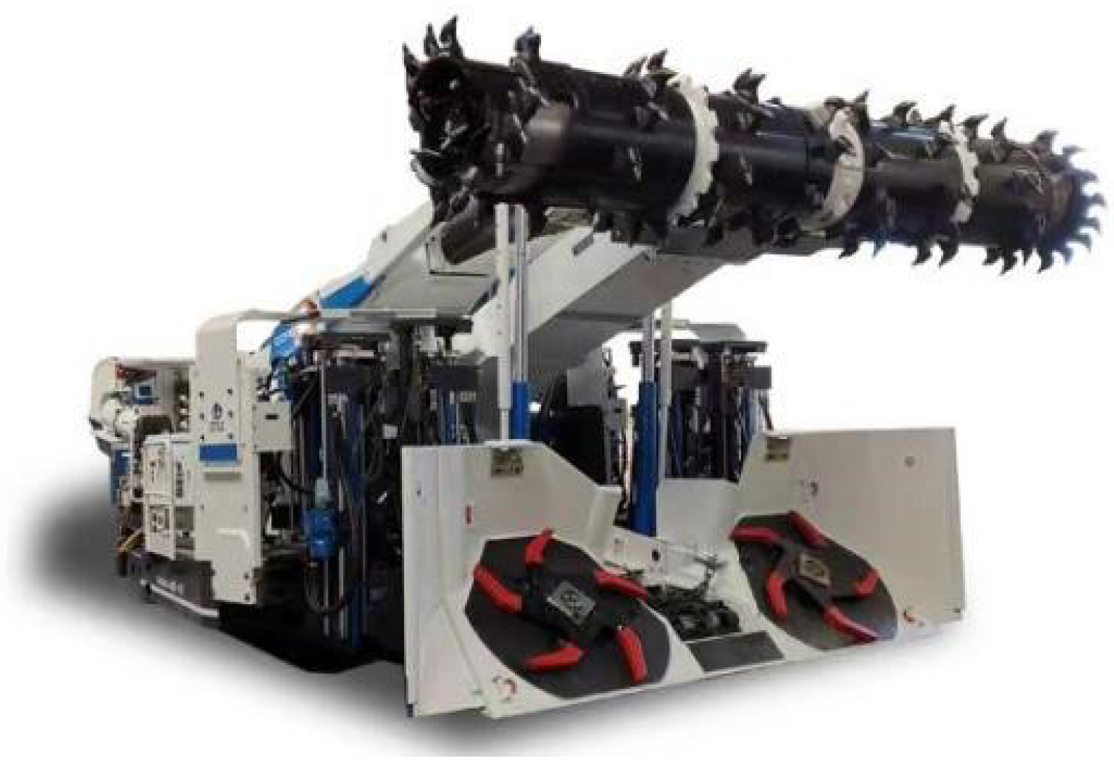
The full-width horizontal-axis roadheader is presented in
Figure 1. The driving and correction of the roadheader can be regarded as the directional driving process of steering and correction of slow, large tracked vehicles. Therefore, the roadheader’s motion can be converted into a two-dimensional sports problem in the horizontal tunnel space.
In the operation process, due to the internal slippage of the roadheader and the influence of changes in the external environment, the actual route will be far from the preset trajectory, affecting the working process and operation efficiency. Therefore, some specific control measures can be taken to monitor the position and posture of the roadheader center in real time. By actively adjusting the linear speed and angular speed of the roadheader, the error between the real route and the preset trajectory can be reduced, which allows the roadheader to automatically move along the desired trajectory and maintain consistency with the virtual target track. The consistency includes position, posture, linear velocity, and angular velocity on the preset trajectory.
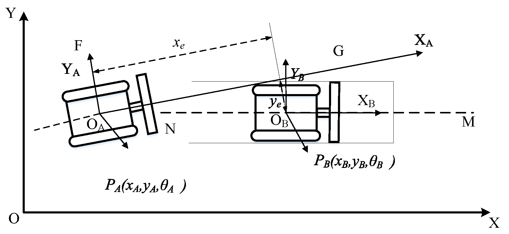
Figure 2 is a schematic tracking diagram of the trajectory tracking of the roadheader. The roadheader on the right is the target position. It is a virtually nonexistent roadheader, which always follows a trajectory path MN set within the global reference frame. At any time, its position and posture always match the preset values. Within the framework of the global coordinate system, the position and posture of the target roadheader are expressed as
, and the linear velocity and angular velocity are indicated
. The roadheader deviates from the preset trajectory MN and arrives at point OA. At this point, the position and posture of the actual roadheader are represented as
, and the linear and angular velocities are expressed as
.
According to
Figure 2, the posture error equation of the target and actual roadheader is solved by Equation (1).
where
is the location and attitude of the target roadheader.
is the location and attitude of the actual roadheader.
Equation (1) is the posture error equation under the global coordinate system. Under the local reference frame, the trajectory error is presented in Equation (2).
where
is the horizontal error of the roadheader in the tunnel.
is the vertical error.
is the angular error of the roadheader. The position error is presented in Equation (3).
where
is the angular velocity of the roadheader in the real position.
is the linear velocity of the roadheader in the real position.
and
are the linear and angular speed of the roadheader in the target position, and the corner error is
.
According to the analysis presented, the track tracking of the roadheader can be termed as the problem of moving the roadheader to the target position by finding the appropriate and under the action of the control law, that is, .
4. Correction Control Method for Roadheaders
4.1. BP Neural Network
The determination of conventional PID parameters mainly relies on a large number of repeated experiments, which not only increases experimental time but also cannot guarantee accuracy [
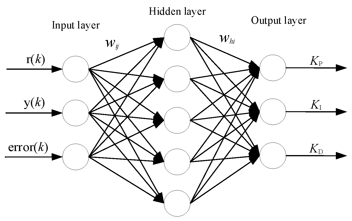
27]. The BP neural network features nonlinear mapping and adaptive learning capabilities. It is well-suited to address issues that have intricate inner workings. The layout of the BP neural network is presented in
Figure 4. It [
28] includes an input layer, a hidden layer, and an output layer. Considering the characteristics of the roadheader, the total number of neurons in the hidden layer is 5, and the neural network structure of “3-5-3” is used for analysis.
Set the input layer’s input to match its output:
where
refers to the projected driving speed,
y(
k)
refers the current driving speed,
error(
k)
denotes the discrepancy between the feedback of the system output and the anticipated value. The inputs and outputs are presented in Equations (16) and (17).
where
refers to the input of the activation function for the
ith hidden layer neuron.
refers to the link weight.
refers to the activation value of the
jth neuron.
refers to the output of the
ith neuron.
The activation function of the hidden layer adopts the hyperbolic tangent function presented in Equation (18).
The input and output functions of the output layer are presented in Equations (19) and (20)
where
refers to the input of the
hth neuron.
refers to the link weight.
refers to the output of the
hth neuron.
4.2. PSO Algorithm
The PSO initializes a group of particles. The paper assumes that there are n particles, and the location and speed of the ith particle are represented as , .
During each iteration, the particles update their velocities and positions through the specific extreme value
and the aggregate extreme value
with the following update formula:
where
is the inertia weight.
is the total iterations.
and
are the domestic and overall best locations, respectively.
and
are the learning factors.
and
are the arbitrary variables in the range [0, 1].
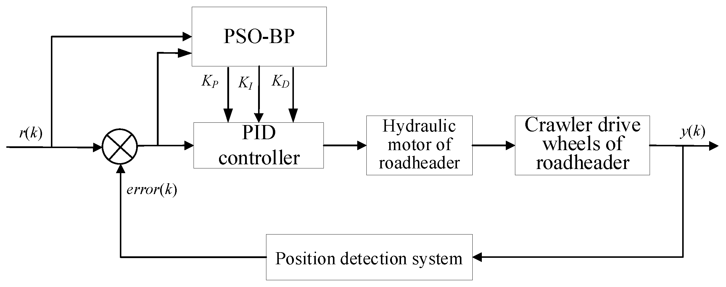
4.3. Design of PID Controller Based on PSO-BP Neural Network
The operating environment of the roadheader is closed, and the allowed adjustment angle is limited, which requires higher precision of deviation correction control. The PID algorithm cannot meet the requirements of control accuracy. BP control can deal with the complex problem. It can adapt the controller parameters. PSO is capable of addressing the initial parameter selection issue for BP [
29], which improves the control performance and robustness of the system and makes the effect of deviation correction control reach its best level [
30]. The PSO-BP neural network framework follows Tang et al.’s methodology [
31], where particle swarm optimization dynamically initializes BP network weights. For PID control implementation, we adopt the PSO-BP hybrid algorithm proposed by Si et al. [
32], which synergizes PSO’s global optimization with BP’s gradient descent for enhanced control stability. The full-width horizontal-axis roadheader PID controller framework involving PSO-BP is presented in
Figure 5.
The PSO algorithm first optimizes the initial weight parameters of the BP network, ensuring a more effective starting point for training. These refined weights are then passed to the BP network, which dynamically adjusts the three PID parameters in real time.
As a population-based stochastic optimization technique, PSO exhibits strong global search capabilities. It employs a linear decreasing inertia weight strategy to balance global exploration and local exploitation [
33], with symmetrically configured learning factors that ensure rapid convergence while maintaining optimization precision. This approach significantly improves the algorithm’s efficiency.
The BP network adaptively generates PID parameters by minimizing prediction error via gradient descent. While traditional BP networks suffer from slow convergence and sensitivity to initial weights [
34], the integration of PSO-optimized initialization mitigates these issues. By providing near-optimal starting weights, the hybrid PSO-BP framework accelerates convergence and enhances generalization, preventing suboptimal local minima.
The combined PSO-BP approach ensures rapid initial parameter optimization through PSO, followed by adaptive fine-tuning via the BP network. This dual-stage mechanism delivers high-precision deviation correction control, meeting the stringent requirements of roadheader operation.
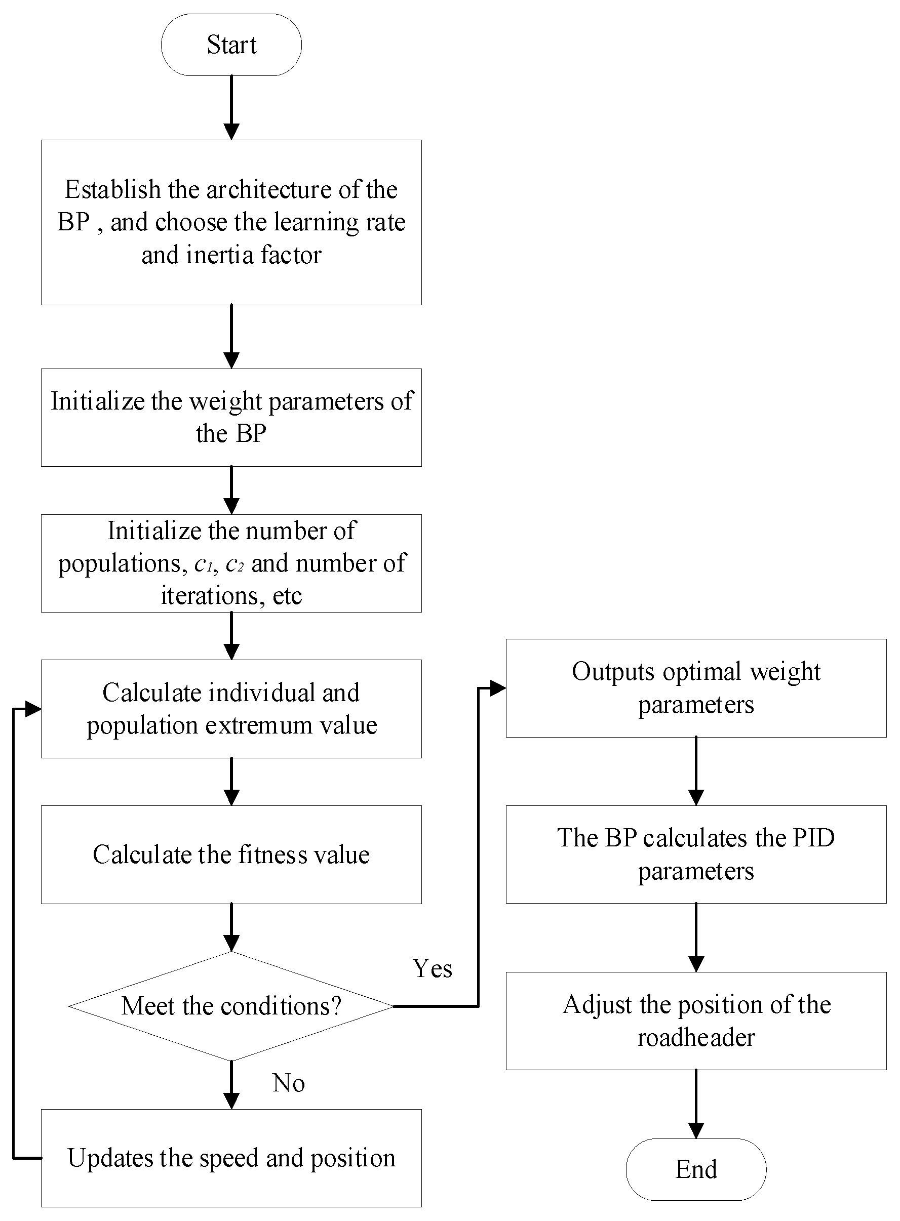
The following describes the sequence of the algorithm and the selection of some parameters for the PSO-BP. A flow diagram of PSO-BP PID is presented as
Figure 6.
(1) Selection of the parameters of the PSO algorithm
The dimension D of the particle is presented in Equation (23).
where H, I, and
O represent the counts of hidden, input, and output layers. The population size, denoted by n, equals 50; the total number of iterations is 80; the learning factor is chosen as
c1 =
c2 = 1.49. The weight is presented in Equation (24).
where the inertia weights of the particle are between 0.4 and 0.9, and
m is the count of the present iteration.
(2) Constructing the fitness function
To measure the effect of particle swarm optimization on the full-width horizontal-axis roadheader, the output variance of BP and the expected value are used as a fitness function to evaluate the quality of the particle position.
(3) Each particle moves with the individual finest location and the team’s finest location as the target, and the speed and location of the particle are regularly updated to obtain the initial weight parameters.
(4) The BP calculates the output signal based on the input signal and weight information to obtain the best parameters. The BP tunes the linking weights through backpropagation to realize the automatic online update of the PID parameters of the roadheader.
5. Experimental Validation and Analysis of Deviation Correction Control of Roadheaders
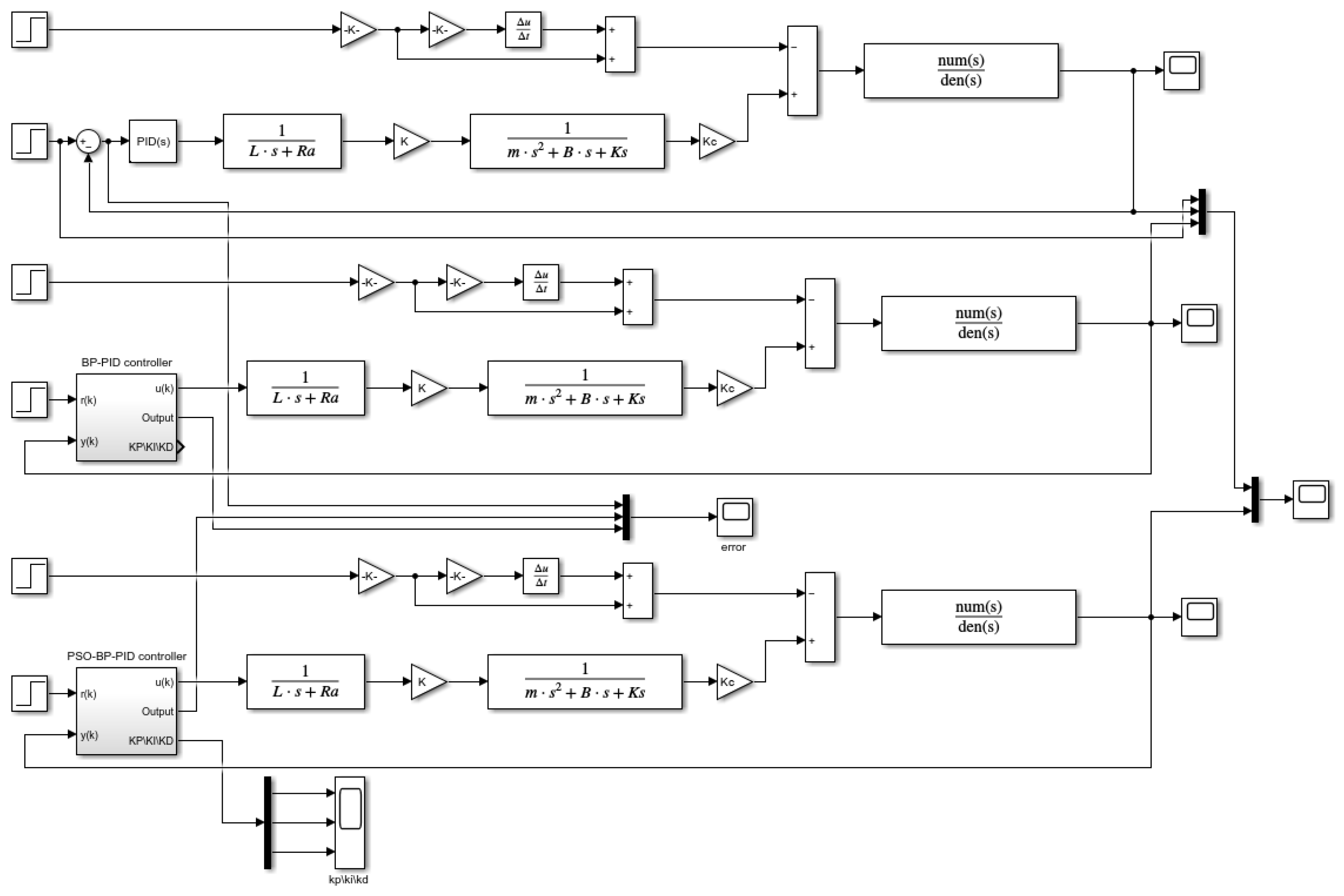
5.1. Simulation Model of Deviation Correction Control System
To investigate the performance of the PSO-BP PID algorithm, simulation experiments were conducted in Simulink, and the model of deviation correction control is presented in
Figure 7.
The controller employs a PID algorithm optimized via PSO-BP, where the PSO component is configured with a dimension of 30, a population size of 50, learning factors
c1 =
c2 = 1.49, and an inertia weight adopting a linear decreasing strategy (0.9–0.4) to achieve a smooth transition from global exploration to local convergence. The BP neural network features a three-layer 3-5-3 structure, with the input layer receiving the desired value, current value, and error signal and the output layer generating PID parameters
,
, and
. The simulation solver utilizes the variable-step ode45 method, with a maximum step size set to 0.01 s and a relative tolerance of 1
to meet control accuracy requirements. Key parameters of the hydraulic system strictly adhere to the measured data listed in
Table 1 and are precisely configured in each Simulink submodule, ensuring the accuracy of the system dynamics modeling. This design comprehensively considers system dynamic response characteristics, algorithm convergence requirements, and actual engineering conditions, enabling a complete representation of system performance under typical input signals such as step, sinusoidal, and square waves.
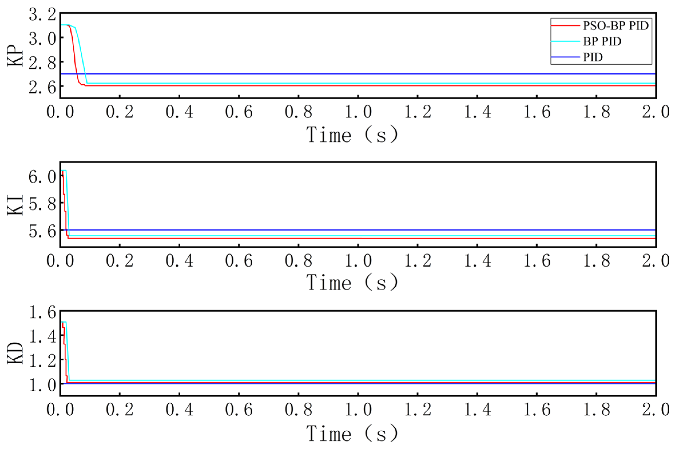
5.2. Simulation Verification and Analysis of Deviation Correction Control
The parameter graph of PSO-BP PID control is presented in
Figure 8. The PSO-BP can tune proportional, integral, and differential parameters to converge rapidly and remain stable in a short time. It has been demonstrated that the PSO-BP has reliable tuning ability.
To confirm the efficiency of the PSO-BP PID algorithm, the step signal, sinusoidal signal, and square wave signal are input into it. The PSO-BP PID is contrasted with the PID and BP PID algorithms.
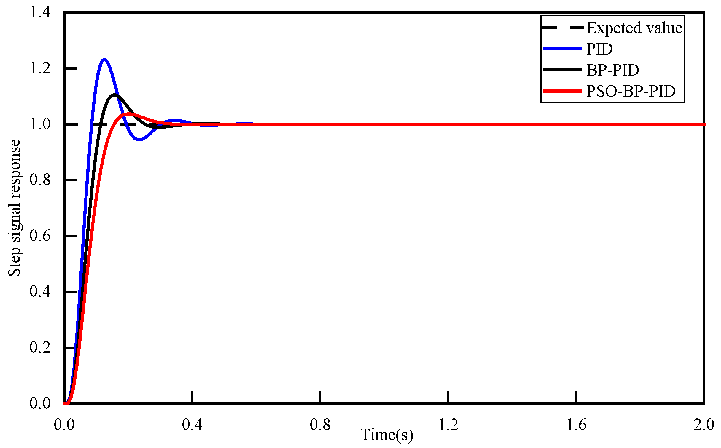
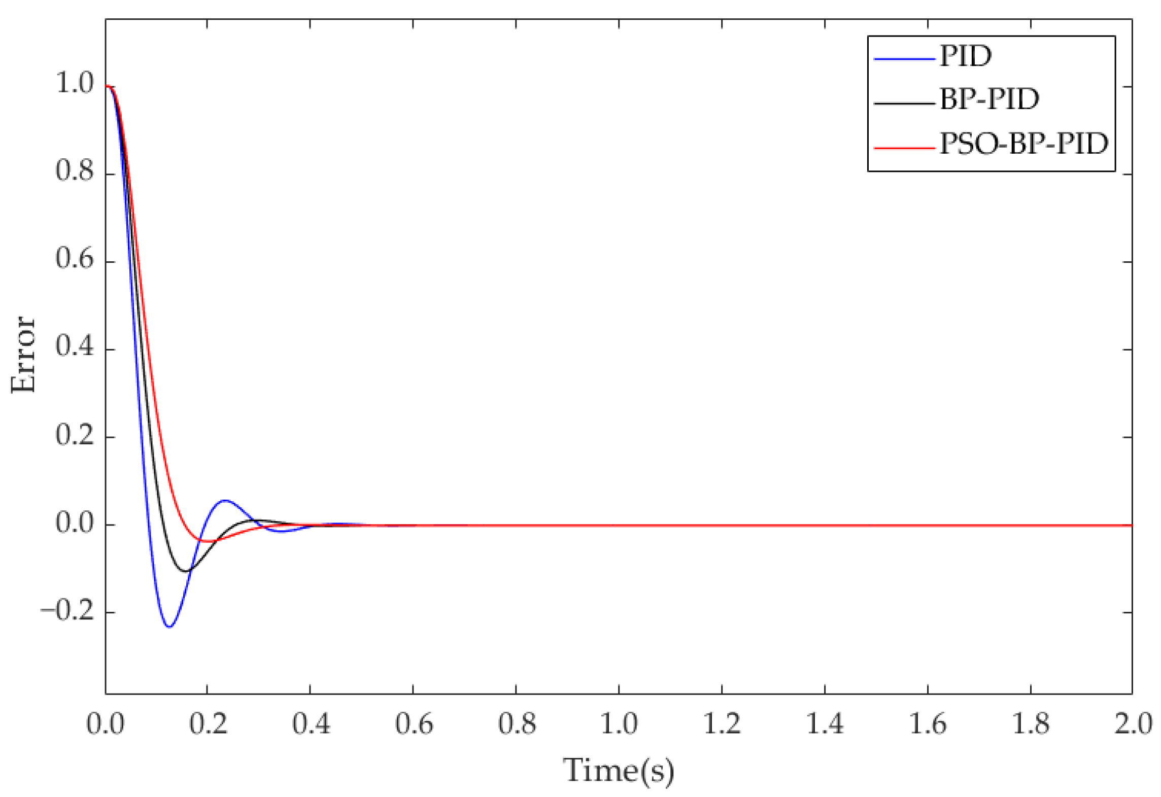
The step response curves of three PID algorithms are presented in
Figure 9. The error curves of the step signal response are presented in
Figure 10. The traditional PID control reaches a stable state after 0.63 s. When BP PID is used, the system stabilizes at 0.40 s. When the PSO-BP PID is used, the system stabilizes at 0.35 s. PSO-BP PID reduces steady-state time by 44.44% and overshoot by 83.47% compared to PID. PSO-BP PID decreases steady-state time by 12.50% and overshoot by 58.76% compared to BP PID.
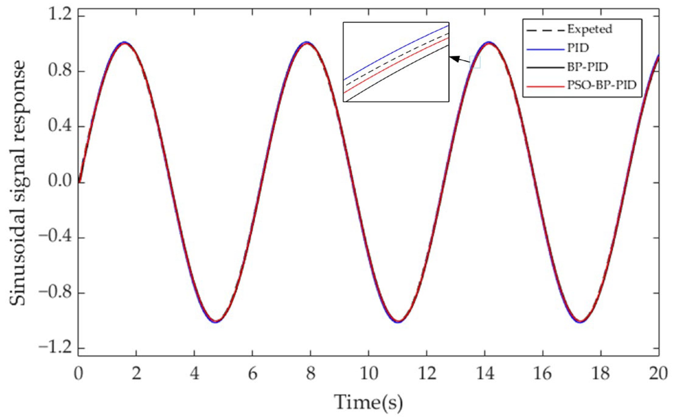
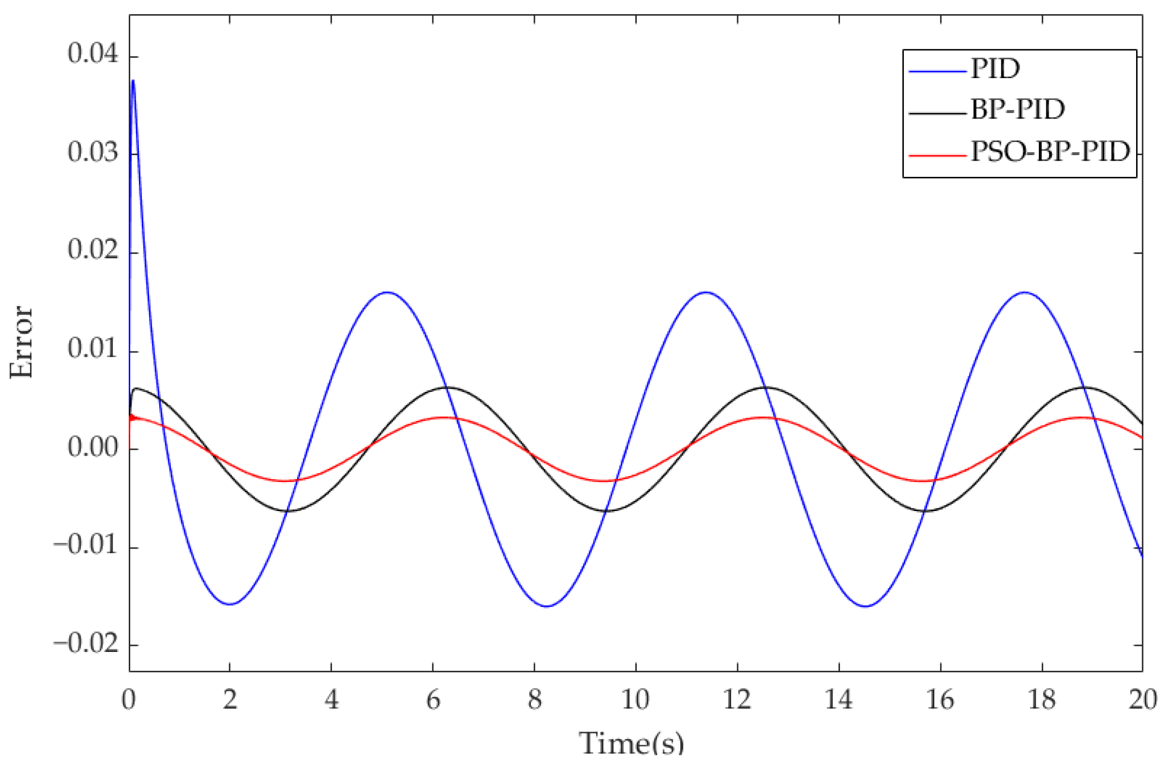
The sinusoidal response curves of three PID control algorithms are presented in
Figure 11. The error curves of the sinusoidal signal response are presented in
Figure 12. The PSO-BP PID control still maintains good tracking and control performance under the sinusoidal signal. The steady-state response time of PSO-BP PID control is 66.96% and 41.54% less than that of PID and BP PID control. The overshoot is reduced by 89.47% and 42.86%, respectively.
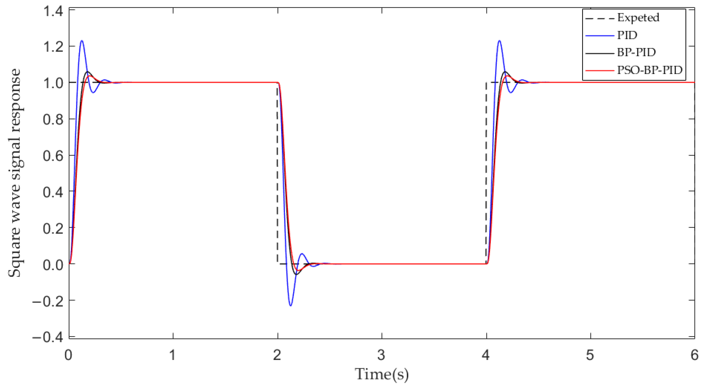
The square wave response curves of three PID control algorithms are presented in
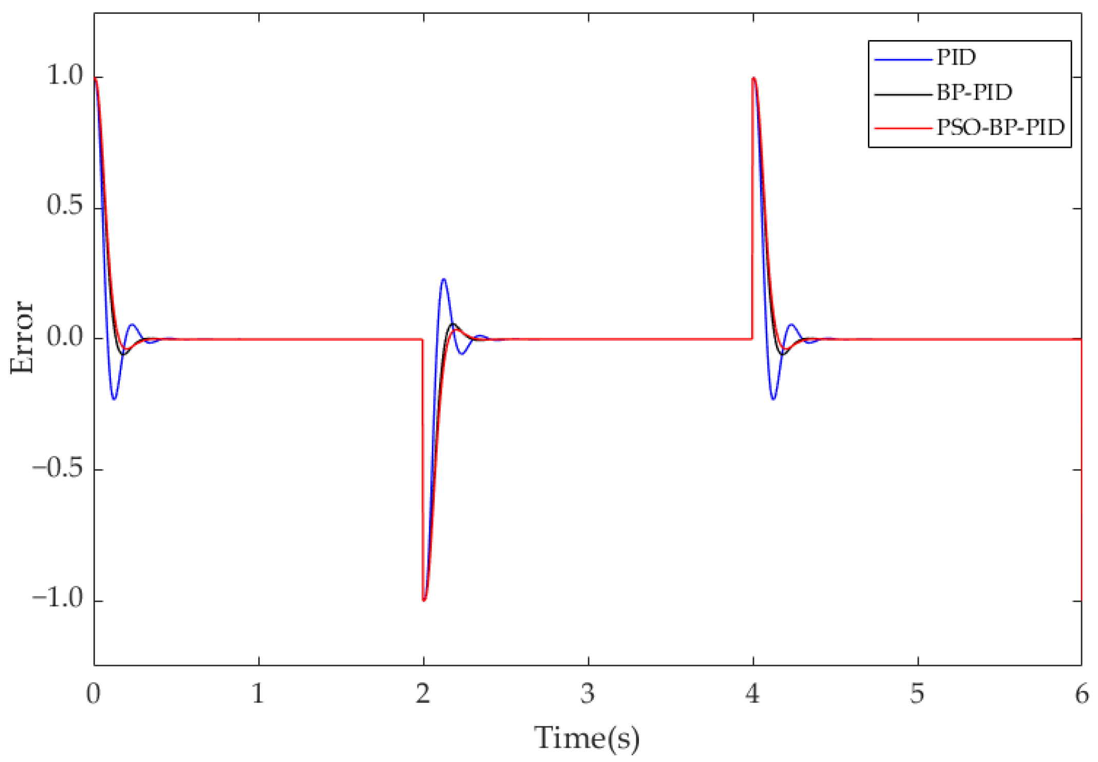
Figure 13. The error curves of the square wave signal response are presented in
Figure 14. The PID reaches a stable state after 0.77 s, which is a slow response. The regulation time of the system with PSO-BP PID is 0.34 s, which is shorter than the time required for the PID and BP PID control to reach the steady state. The overshoot of PSO-BP PID control is reduced by 87.11% and 49.12%, respectively.
The comparative results of three PID control algorithms are presented in
Table 2. PSO-BP PID control has a shorter response time, which can rapidly and accurately realize deviation correction control.
5.3. Experimental Verification of Roadheader Deviation Correction Control
To demonstrate the performance of the PSO-BP PID control algorithm in deviation correction control, a roadheader is used as an experimental subject, with a length of 11.6 m, a width of 5 m, and a height of 2.6 m. The tunnel center line is set as the reference trajectory for roadheader movement. According to our team’s previous research [
35], the initial declination angle of −2° is taken as an example to implement the experiment.
(1) Construction of a walking mechanism control system for the experimental prototype of the roadheader
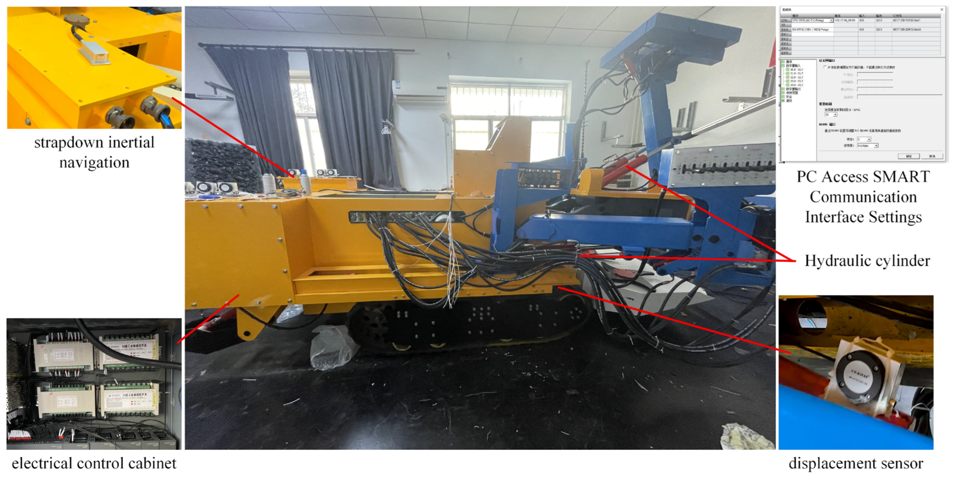
The experimental platform consists of strapdown inertial navigation, displacement sensor, remote intelligent industrial control machine, onboard PLC, electrical control cabinet, and pushing cylinder, which are presented in
Figure 15. The information to be collected in this experiment includes the spatial coordinates, deflection angle, and angular velocity of the roadheader.
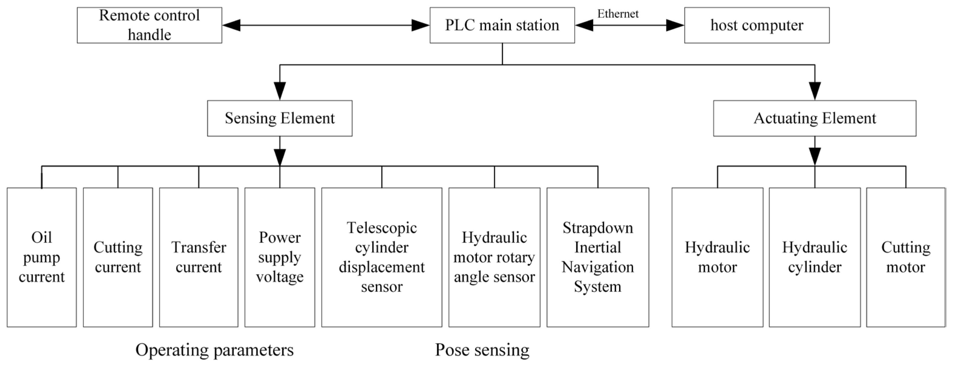
The system structure is shown in
Figure 16. The onboard PLC communicates with the remote intelligent industrial control computer through Ethernet, and the neural network PID correction control algorithm is imported into the upper computer for PLC compilation. Then, a connection is established between the upper computer and the S7-200 SMART CPU, and control instructions are downloaded to the onboard PLC controller to control the movement of the tunneling machine.
The control instructions configured by the upper computer are analyzed by the PLC to adjust the hydraulic servo system of the tunneling machine in real time, driving it to move on the preset trajectory. The closed-loop control of state variables is realized.
The real-time operation data of the roadheader is collected by sensors and uploaded to the upper computer. The system dynamically compares it with the target value set internally by the controller and calculates the error amount.
The system outputs new PID control parameters based on real-time error results, achieving online adaptive adjustment of the excavation process. The control effect will be applied in the next control cycle, thus achieving a closed loop of self-learning and self-optimization correction control.
With the target declination angle, the roadheader steering is controlled based on the angle deviation to adjust the roadheader’s declination angle. Finally, the deviation correction control is implemented.
(2) Analysis of experimental results
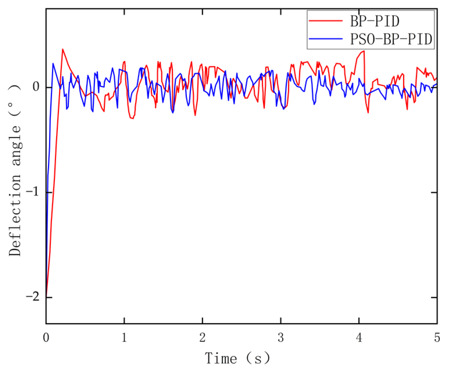
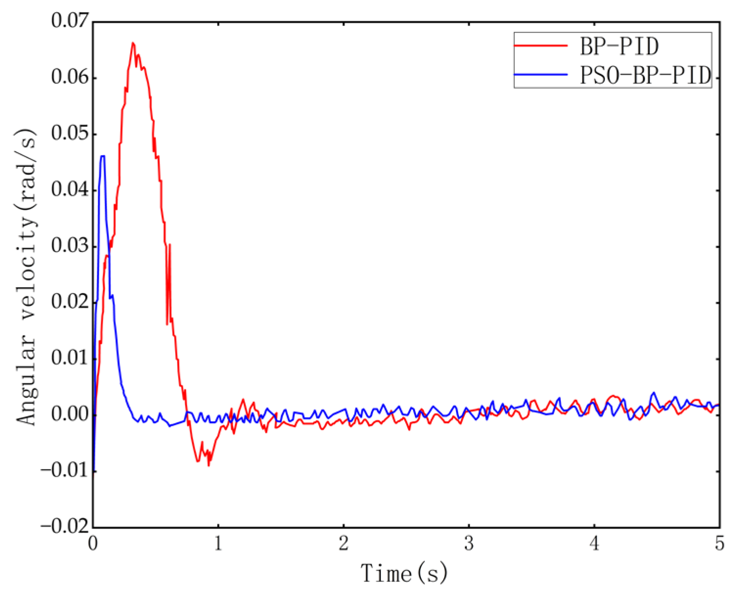
Based on the strategy of control, when the roadheader is misaligned with the center line of the tunnel, it is necessary to deflect a certain angle to make the roadheader return to the center line. Firstly, when the roadheader is in the initial position, its left and right tracks move in reverse to perform in situ steering at an angle of 2°. The change in the deflection angle and the change in the angular velocity of the roadheader are presented in
Figure 17 and
Figure 18.
Figure 17 illustrates that, after the deviation correction control, the angle deviation of the roadheader gradually decreases, and the angle deviation of the roadheader generates a certain overshoot. The fluctuation in the process of deviation correction is due to the instability of the fuselage and the interference of external factors such as inertial guidance accuracy. The BP PID control needs 0.77 s to stabilize the error at around 0°, and its rise time is too long. However, the PSO-BP PID control only needs 0.29 s and has a shorter rise time.
Figure 18 illustrates that the angular velocity increases rapidly at the beginning and then decreases rapidly after receiving the stop control signal until the deflection angle is stabilized at about 0°. Regarding response speed and error variation, although effective deviation correction can be implemented by using BP PID control, the delay of angular velocity adjustment is larger, and the adjustment time is longer. Therefore, PSO-BP PID control is more effective. The data are presented in
Table 3.
6. Conclusions
To address the issue of trajectory deviation in full-width horizontal-axis roadheaders under complex and variable tunnel conditions, a PSO-BP PID-based deviation correction control method is proposed. The conclusions from simulations and experimental analyses indicate the following:
(1) The kinematic analysis of the roadheader walking mechanism is carried out, and a trajectory error model of the walking system is established. Combined with the hydraulic system of the roadheader walking mechanism, the transfer function of the hydraulic system is solved. The PSO-BP PID controller’s architecture is in place.
(2) Three different signals are input to the control system for simulation verification. The findings demonstrate that the PSO-BP PID can realize deviation correction control with faster speed and higher accuracy. The control effect surpasses both BP PID and PID control.
(3) Taking a full-width horizontal-axis roadheader as the experimental object, a deviation correction control experiment was carried out. The experiment concluded that the PSO-BP PID control mechanism achieves a maximum steady-state error of 0.23° in deflection angle and 0.0038 rad/s in angular velocity. This control mechanism can better accommodate the deviation correction control needs of the roadheader.
The current experimental validation was conducted in a controlled environment, but future studies should implement underground field tests to evaluate the system’s performance under real mining conditions with complex geological factors such as uneven road surfaces and rock fragmentation interference. This study enhances roadheader safety through real-time collision risk correction, optimizes resource utilization by minimizing over-excavation and under-excavation via precise control, and advances the development of unmanned tunneling technology.

