1. Introduction
Developing renewable energy resources and achieving long-distance energy transmission constitutes a fundamental strategy for future energy and power industry construction. This helps maintain optimal resource allocation and stable energy supply [
1]. For long-distance and large-capacity power transmission systems, high-voltage direct current (HVDC) has emerged as the preferred solution for power delivery [
2]. Considering that thyristors have control flexibility [
3], line-commutated converter (LCC)-based HVDC technology is currently widely used in large-capacity power transmission [
4]. However, commutation failure (CF) is an inherent challenge in LCC-HVDC systems. According to the statistics in [
5], from 2004 to the end of 2018, a total of 1353 CF incidents occurred in the DC transmission system of the State Grid in China, with an average of 9.1 CFs per DC transmission system per year. Among the 1353 CFs, 1209 were caused by alternate current (AC) system failures, accounting for 89.36% of the total failures, indicating that AC system failures are the primary causes of CFs [
6].
In [
7], the commutation mechanisms and causation of CFs are analyzed, and existing CF suppression strategies are classified into the optimization of HVDC control systems, fault current limiting, and series-parallel reactive power compensation equipment. Nevertheless, this taxonomy does not highlight the main methods for solving CF. In existing research, the solutions for resolving CF include the addition of reactive power compensation equipment on the AC side, the promotion of system control, and the transformation of the LCC topology. Among the aforementioned solutions, the new LCC topology is the most promising solution.
In terms of adding reactive power compensation equipment, the influence of synchronous capacitors on the mitigation of CFs is analyzed in [
8]. In [
9], a static synchronous compensator is proposed as a parallel reactive power compensation solution connected to the weak AC terminal on the inverter side of an HVDC transmission system. The coordinated power control of electrochemical energy storage is proposed in [
10] to alleviate the consequent commutation faults of HVDC transmission systems. While series-parallel reactive power compensation equipment can improve the voltage drop on the AC side to a certain extent and have a positive impact in terms of resisting CFs, using a large quantity of reactive power compensation equipment increases the investment cost.
In terms of system control, a new method for calculating the commutation voltage under unbalanced faults is proposed in [
11], which can significantly improve the accuracy of CF prediction. Ref. [
12] proposes a CF suppression technique based on the dynamic tracking of the extinction angle. A new CF prediction and prevention strategy is proposed in [
13], which takes into consideration the probabilistic characteristics of CF to predict CF more accurately than traditional methods. In [
14], a method for lowering the risk of CF in HVDC systems is proposed, which requires continuous voltage monitoring and calculating changes in observed voltage. Some control methods proposed by other scholars are characterized by the direct control of the inverter’s firing angle to ensure a sufficient commutation margin during forward voltage recovery, while minimizing the negative impact of increased reactive power consumption by avoiding the “excessive leading” of the inverter’s early trigger angle [
15]. The algorithm discussed in [
16] takes into consideration the AC voltage drop, DC current increase, phase voltage crossover offset, and control characteristics of the HVDC transmission system.
In terms of the topology transformation of an LCC-HVDC system, the controllable commutation converter proposed in [
17] was implemented in the Gezhouba–Shanghai project, but the system cost was high. In [
18], resistor–capacitor sub-modules were connected in series with the thyristor arm to compensate for AC voltage drop and prevent the increase in fault currents. In [
19,
20], sub-modules with different structures were connected in series with the inverter bridge arm to increase the commutation voltage and resist CF. In contrast to [
18], the characteristics of thyristors were taken into consideration and a path was provided for the reverse freewheeling current. However, this resulted in an increase in the number of fully controlled devices and an increase in the system cost. Instead of connecting sub-modules in series with the valve arm, hybrid converters were proposed in [
21,
22] in which full-bridge sub-modules realized using an insulated gate bipolar transistor (IGBT) were connected in series with an integrated gate-commutated thyristor (IGCT) between the AC transformer and the LCC. The full-bridge sub-module enabled the dynamic series insertion of capacitors during commutation to increase the effective commutation voltage, eliminating the commutation voltage drop in the event of a severe fault. In [
23,
24], an evolved capacitor-commutated converter based on a bidirectional full-bridge sub-module was proposed to alleviate the CF. In [
17,
18,
19,
20,
21,
22,
23,
24], although the turn-off characteristics of the thyristor were analyzed, the influence of the dynamic insertion of the sub-module’s capacitor on the thyristor’s turn-off angle was not studied.
A novel sub-module-based CF suppression method for LCC-HVDC systems is proposed in this paper, which can actively mitigate CF by providing the auxiliary commutation voltage to the AC side, and the sub-module is conducive to the rapid recovery of the thyristor’s forward blocking ability; furthermore, the proposed LCC has better economic efficiency comparing with existing strategies. The research results can be applied to all LCC projects in the world, thereby improving the ability of LCC systems to resist to CF.
The remaining part of this article is organized as follows:
Section 2 presents the topology and working principle of the proposed sub-module;
Section 3 discusses the control strategy based on the proposed sub-module structure;
Section 4 studies the electrical stress and economic analysis of the proposed sub-module;
Section 5 analyses the extinguishing angle of the new sub-module; simulation verification is presented in
Section 6; and finally,
Section 7 provides a summary of the article.
2. LCC Topology Based on the Proposed Sub-Module
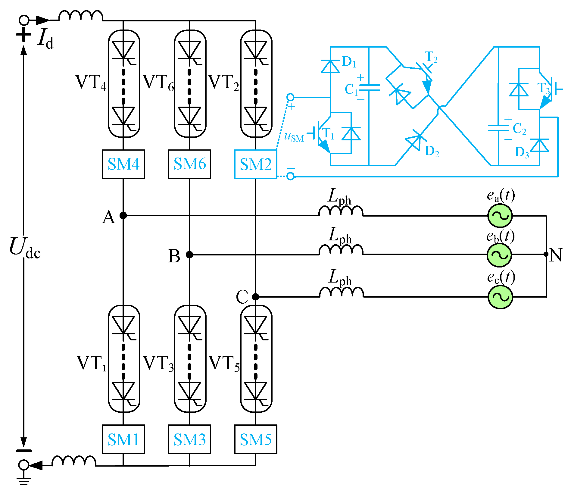
Figure 1 illustrates the proposed LCC topology incorporating the novel sub-module. Unlike the traditional LCC, each valve arm is connected in series with a high-power thyristor and a new auxiliary commutation sub-module. The auxiliary commutation sub-module is a multi-functional sub-module, which consists of three groups of fully controlled devices (T
1–T
3, using IGBTs in this paper), three diodes (D
1–D
3), and two capacitors (C
1–C
2).
uSM is the output of the sub-module.
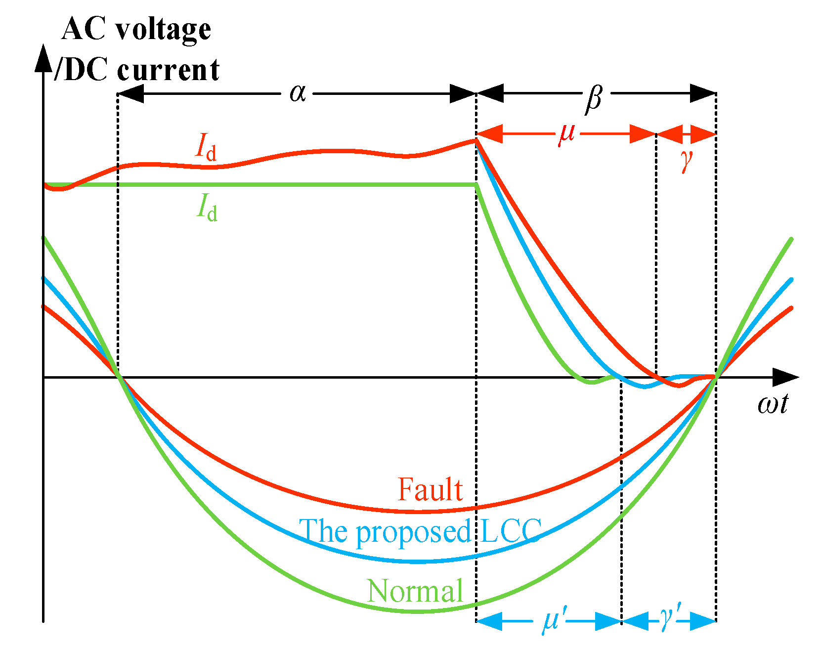
When the LCC inverter is in normal operation, the DC side current is kept constant, and the AC-side line voltage provides a sufficient commutation area in the commutation process. The corresponding commutation voltage curve is shown in green in
Figure 2.
When an AC fault occurs on the AC side of the inverter, the AC voltage drops, resulting in an insufficient commutation area during the commutation process; as a result, the DC current increases. It takes a longer commutation time, μ, to complete the commutation, so the extinguishing angle,
γ, of the thyristor is reduced. When
γ is less than the minimum extinguishing angle,
γmin, the thyristor that needs to be turned off does not fully recover its forward blocking ability within the predetermined time. In such scenarios, when the AC bus voltage changes from negative to positive, if the closing thyristor that has to be in a blocking state is in a conducting state, CF definitely occurs. The commutation voltage curve in this case is shown in red in
Figure 2.
For the LCC with the proposed sub-module, when an AC fault occurs on the AC side of the inverter, the proposed sub-module accelerates the commutation process by providing the auxiliary commutation voltage to the AC side. As a result, the commutation time is reduced, the extinguishing angle is increased, and the probability of successful commutation is improved. The AC voltage and DC current for the proposed case are presented in
Figure 2 in a cyan color.
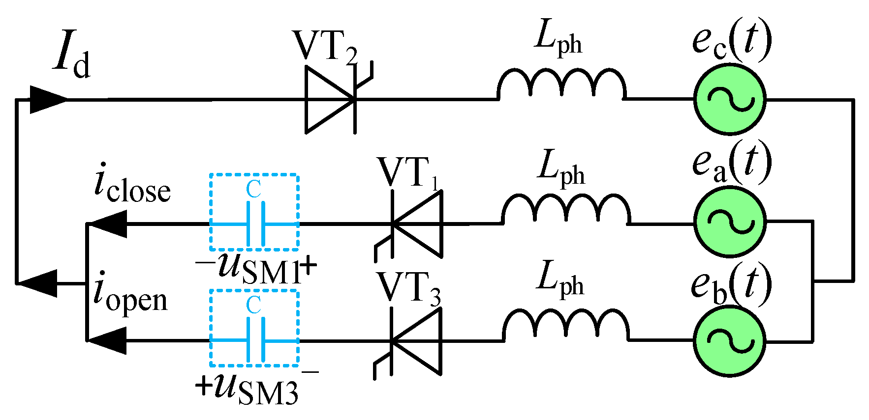
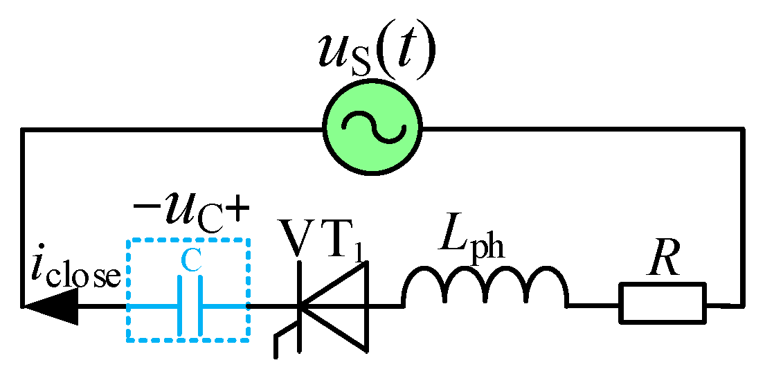
The equivalent circuit of the proposed LCC during commutation is shown in
Figure 3, with the transition from VT
1 to VT
3 analyzed as an example.
According to Kirchhoff’s law,
where
Lph is the equivalent commutation inductance;
iopen (
t) and
iclose (
t) are the arm currents of the opening and closing valves, respectively;
uL (
t) is the line voltage on the AC side;
uSM (
t) is the output voltage of the sub-module; and I
d is the DC current.
From Equations (1) and (2), it can be seen that by controlling the switching of the capacitor voltage of the sub-module, the output voltage of the sub-module can compensate for the voltage drop on the AC side during the fault.
For the proposed sub-module topology, there are eight operational modes, and the switching state of each IGBT in different modes is shown in
Table 1.
It can be seen from
Table 1 that the modes of the proposed sub-module are very flexible. The capacitors can be bypassed, charged, and discharged in different modes, and the sub-module can output five levels of voltage: 0,
uc, −
uc, 2
uc, and −2
uc. The modes of the sub-module can be elaborately selected on the basis of the control strategy of the LCC-HVDC system.
3. Control Strategy of the Proposed Sub-Module
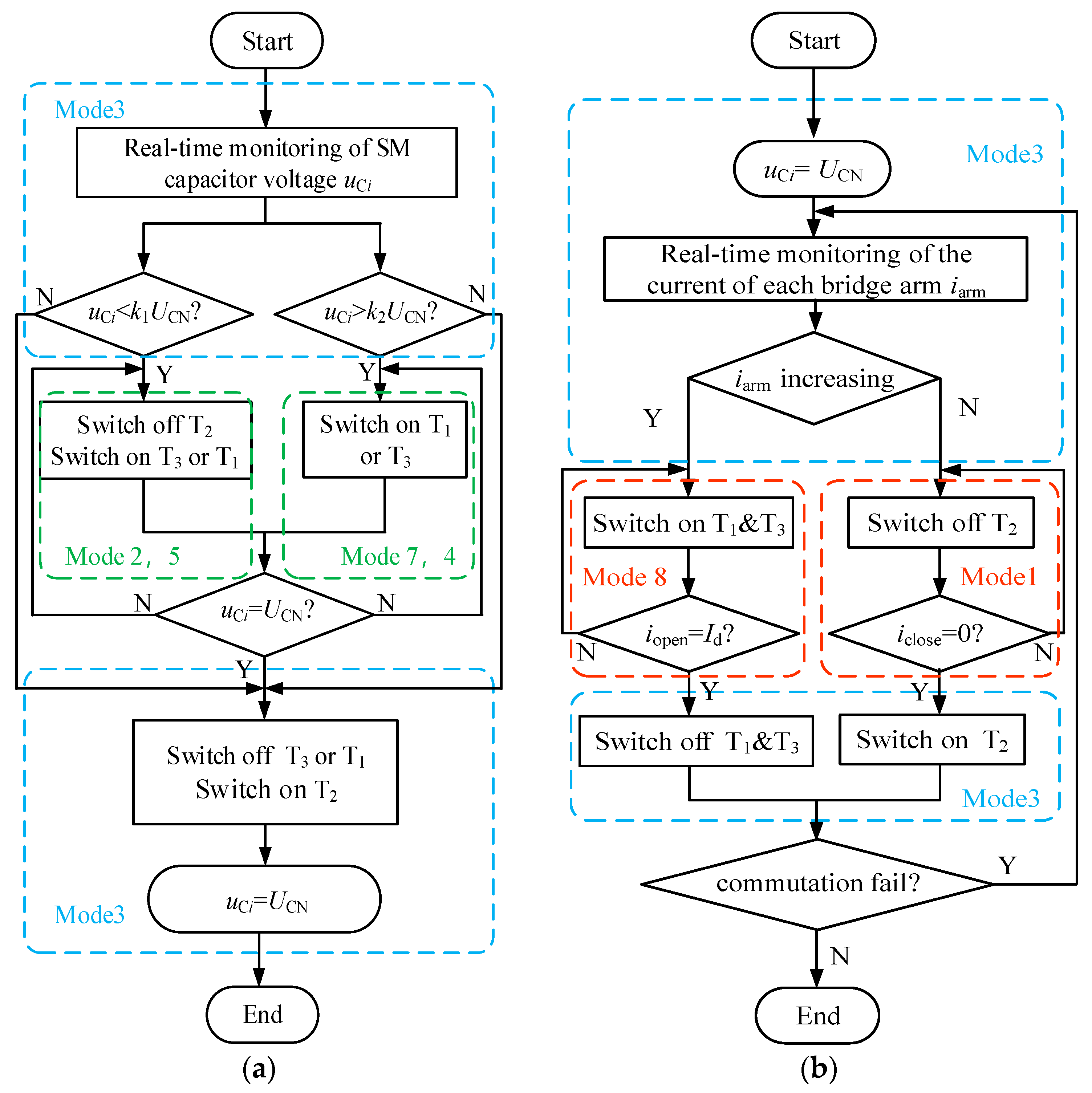
The operation strategies of the proposed sub-module include a capacitor voltage equalization strategy and auxiliary commutation strategy. When the system detects the fault on the AC side, the auxiliary commutation strategy is put into operation to actively accelerate the commutation process and resist CF.
In the auxiliary commutation process, the capacitor voltage needs to be maintained and balanced within a specified range, usually close to the rated voltage of the capacitor. The corresponding control strategy is illustrated in
Figure 4a. When an AC-side fault occurs, the auxiliary commutation strategy is put into operation, as shown in
Figure 4b.
Considering the turn-off characteristics of the thyristor, there is a transient reverse current after the voltage reverses until the thyristor completely recovers the reverse blocking capability because the internal electrons and holes are not completely recombined before the current crosses zero. The proposed sub-module provides a freewheeling path for the reverse current in Mode 8, which facilitates the thyristor’s recovery of its reverse blocking capability and is conductive to accelerating the commutation process.
4. Electrical Stress and Economic Analysis
Since the LCC with the new sub-module is designed with two capacitors, the maximum voltage stresses of T
2 and D
2 are twice the capacitor voltages, while the maximum voltage stresses of other IGBTs and diodes are the same as the capacitor voltage. The voltage stresses of all devices are summarized in
Table 2.
Modes 2, 4, 5, and 7 can work in both normal states and fault conditions, so the current stress analysis of the device was performed under fault conditions. Therefore, when the proposed sub-module works in Modes 1, 2, 4, 5, 7, and 8, the current stress of the switching device is directly related to the fault current
ik. The contemporary stress of the device is consistent with the DC current when the proposed sub-module works in a bypass state and the capacitor voltage-balancing state in Modes 3 and 6. The current stresses of the switching devices under different modes are given in
Table 3.
The operational losses in LCC mainly include switching loss and on-state loss, and on-state loss accounts for a large proportion of the system operational losses. The number of power electronic components required to process the power for the same voltage can be used as the measure of the operational losses of the sub-module.
While existing topologies in [
18,
19] require 2 power electronic devices during commutation, the proposed LCC-HVDC’s sub-module configuration achieves equivalent functionality with only 1.5 devices through shared component utilization. Therefore, the new sub-module proposed in this paper has about 3/4 of the operational losses compared to the other two types of sub-modules discussed in [
18,
19].
5. Commutation Mechanism Analysis
5.1. Commutation Mechanism
The primary cause of CF, which mainly occurs on the inverter station side of the LCC-HVDC system, is the drop in the AC-line voltage when a fault occurs on the AC side, which increases the commutation time and reduces the reverse voltage of the closing thyristors. Therefore, connecting sub-modules in series with the bridge arm to compensate for the voltage drop on the AC line during a fault is the most feasible method of resisting CF [
18,
19,
20,
21]. However, the charging and discharging processes of capacitors are not considered in the commutation theoretical analysis in these studies.
It is noted in [
19] that when there is a fault on the AC side, based on the shunt impedance of the parallel branch, only the negative capacitor voltage is inserted in the closing arm used for the discharging capacitor. Because the DC current
Id can be seen as constant, that is
dId/d
t = 0, it is obtained from Equations (1) and (2) as
Replacing
uL(t) and
uSM3(
t) with their analytical formulas, we obtain
The solution for Equation (4) is given as
where
E is the amplitude of the line voltage;
XL =
ωLph is the equivalent commutation reactance;
ω is the fundamental angular frequency of the AC system; U
CN is the initial capacitor voltage; and
τ is the equivalent commutation time constant.
At the begining moment of the commutation process,
ωt =
π −
β,
t = (
π −
β)/
ω =
α/
ω, and the current does not change abruptly:
iclose1 =
Id. Hence, A
1 can be expressed as follows:
Substituting Equation (6) into Equation (5), we obtain
At the ending moment of the commutation process,
ωt =
π −
β +
μ;
t = (
π −
β +
μ)/
ω = (
α +
μ)/
ω; and
iclose2 = 0. Rearranging Equation (7), we obtain
where
γ1 is the extinguishing angle;
α is the firing angle;
μ is the commutation overlap angle; and
β =
α +
γ.
Compared with the general expression of the extinguishing angle, the value of γ1 from Equation (8) is clearly increased after taking into account the capacitor discharging process of the sub-module.
Based on the above derivation, the system commutation equivalent circuit under the control strategy proposed in this paper is shown in
Figure 3. When a fault occurs on the AC side, the sub-module capacitors are inserted in the commutation circuit to compensate for the AC voltage drop. The corresponding circuit equation can be obtained from Equations (1) and (2) as
where
We assume the sub-module capacitor voltage initially equals zero, such that the charging process represents a pure zero-state response. The equivalent circuit during the charging process is shown in
Figure 5, where
us (
t) is the virtual electromotive force in the zero state response, and R is the commutation equivalent resistance. The expressions that correspond to the zero state are in Equation (11).
where C is the capacitance value and
uC∞ is the capacitor voltage during the steady state. Substituting
iC (0) =
Id when
t = 0 into Equation (11), we obtain
Combining Equations (9)–(12), we obtain
The solution for Equation (13) is given as
At the starting moment of the commutation process, A
2 can be expressed as
Substituting Equation (15) into Equation (14) yields the following expression for
iclose2 (
t):
At the ending moment of the commutation process,
ωt =
π −
β +
μ;
t = (
π −
β +
μ)/
ω = (
α +
μ)/
ω; and
iclose2 = 0.
In HVDC transmission systems, the value of R is generally very small, as can be seen from the distribution parameters. Comparing Equations (8) and (17), it can be clearly seen that the extinguishing angle, γ2, of the proposed LCC-HVDC system is further increased, which provides a longer time for the thyristor to recover its forward blocking ability so as to promote the system’s ability to resist CF.
5.2. Design of Capacitor of Sub-Module
In order to achieve the auxiliary commutation of the LCC via the proposed sub-module, so as to improve the ability of the proposed LCC to resist CF, it is necessary to balance and set an appropriate initial value of the capacitor voltage before the sub-module is put into auxiliary commutation. The optimal initial voltage of the capacitor in the discharging branch is studied in [
19], but the initial optimal voltage of the capacitor in the charging branch is not studied. The capacitor states in the proposed sub-module during the commutation process are analyzed below.
During the VT
1-to-VT
3 commutation transient, Equations (1) and (2) can be used to obtain
According to Equations (11) and (18),
Applying the Laplace transform to Equation (19), we obtain
At the initial moment of the sub-module capacitor’s charging, the boundary condition is
Substituting Equation (21) into Equation (20), we obtain
Applying the inverse Laplace transformation to Equation (22), we obtain
where
ωt ∈ [0,
μ].
In order to realize auxiliary commutation, the sub-module capacitor is inserted and charged to compensate for the AC voltage drop. To prevent the charging voltage from being too high, damaging the sub-module capacitors, the following condition is imposed on the charging time [0,
μ]:
It can be seen from Equation (25) that in order to make the sub-module capacitor voltage in the closing branch not exceed 2UCN during the charging process, there is a maximum value of the initial voltage uC(0), which is related to the rated capacitor voltage of the sub-module UCN, the commutation inductance Lph on the AC side, the capacitance value C, the system angular frequency ω, the firing angle α, the commutation overlap angle μ, the AC line voltage E, and the DC current Id. In a steady state, these eight parameters are constant, and there is an optimal initial capacitor voltage. In a transient state, the AC line voltage amplitude decreases while the DC current rises; that is, uC (t) < 2 UCN. Therefore, the initial capacitor voltage should be lowered to ensure successful commutation while ensuring the capacitor voltage is not overcharged.
6. Simulation Results and Discussion
6.1. Simulation Model
To verify the effectiveness of the LCC topology with the proposed sub-module, this paper built the proposed LCC based on the CIGRE standard test model. The electrical stress and the ability of the proposed LCC system to actively resist CF were verified on the MATLAB R2020a/Simulink R2020a simulation platform. In terms of the control mode, the control strategy of the proposed LCC system is the same as the CIGRE standard test model. The rectifier side adopts constant current control and is equipped with low-voltage current limiting control. The inverter side adopts fixed extinguishing angle control, and the parameters of the inverter side are given in
Table 4.
6.2. Electrical Stress
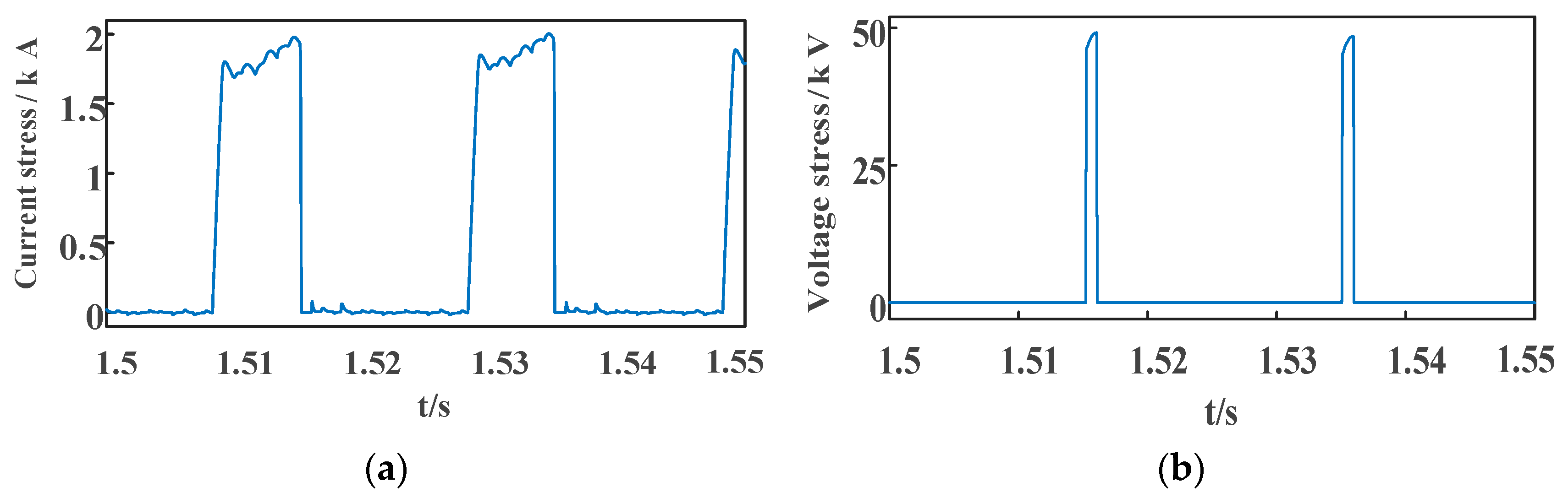
The proposed LCC-HVDC system was subjected to a phase inductive short-circuit grounding fault on the AC side of the inverter, in which the fault grounding inductance value was 0.25 H and the rated sub-module capacitor voltage was 25 kV. The fault was switched on at 1.5 s, and the assisting commutation control strategy was activated after a delay of 0.01 s. The fault with a duration of 50 ms ended at 1.55 s, and the system was successfully commutated. The electrical stress of switching device T
2 in the proposed sub-module is illustrated in
Figure 6.
It can be observed in
Figure 6 that in the case of the single-phase short-circuit grounding fault, the maximum current stress of the switching device T
2 is 2.01 kA, which meets the current design requirements. The maximum voltage stress is 49.1 kV, which is nearly 2 U
CN, which verifies the voltage stress analysis described in
Section 3. For practical purposes, the voltage stress of T
2 is twice that of T
1 and T
3. Considering the investment cost, T
2 can be realized with two identical (in terms of voltage-withstanding capability and characteristics) series-connected switches. In this case, the voltage stress of each switch can be maintained within U
CN.
6.3. Actively Resisting CF
The proposed strategy is compared with other solutions in detail in
Table 5. It can be seen that only the proposed strategy has a freewheeling pathway; Ref. [
19] and the proposed strategy are the most similar, so this article compared them through simulation.
To verify the ability of the proposed LCC-HVDC system to actively resist CF, we conducted a simulation and comparative analysis in terms of six aspects: DC current, DC voltage, active transmission power, extinguishing angle, bridge arm current, and sub-module capacitor voltage. In particular, the following three cases were considered:
Case 1: a traditional LCC-HVDC system (the CIGRE standard system test model);
Case 2: the model discussed in [
19];
Case 3: the proposed LCC-HVDC system.
The parameters of the rectifier sides of the above three cases were the same, and the parameters of the inverter sides were the same as those discussed in
Section 5.1.
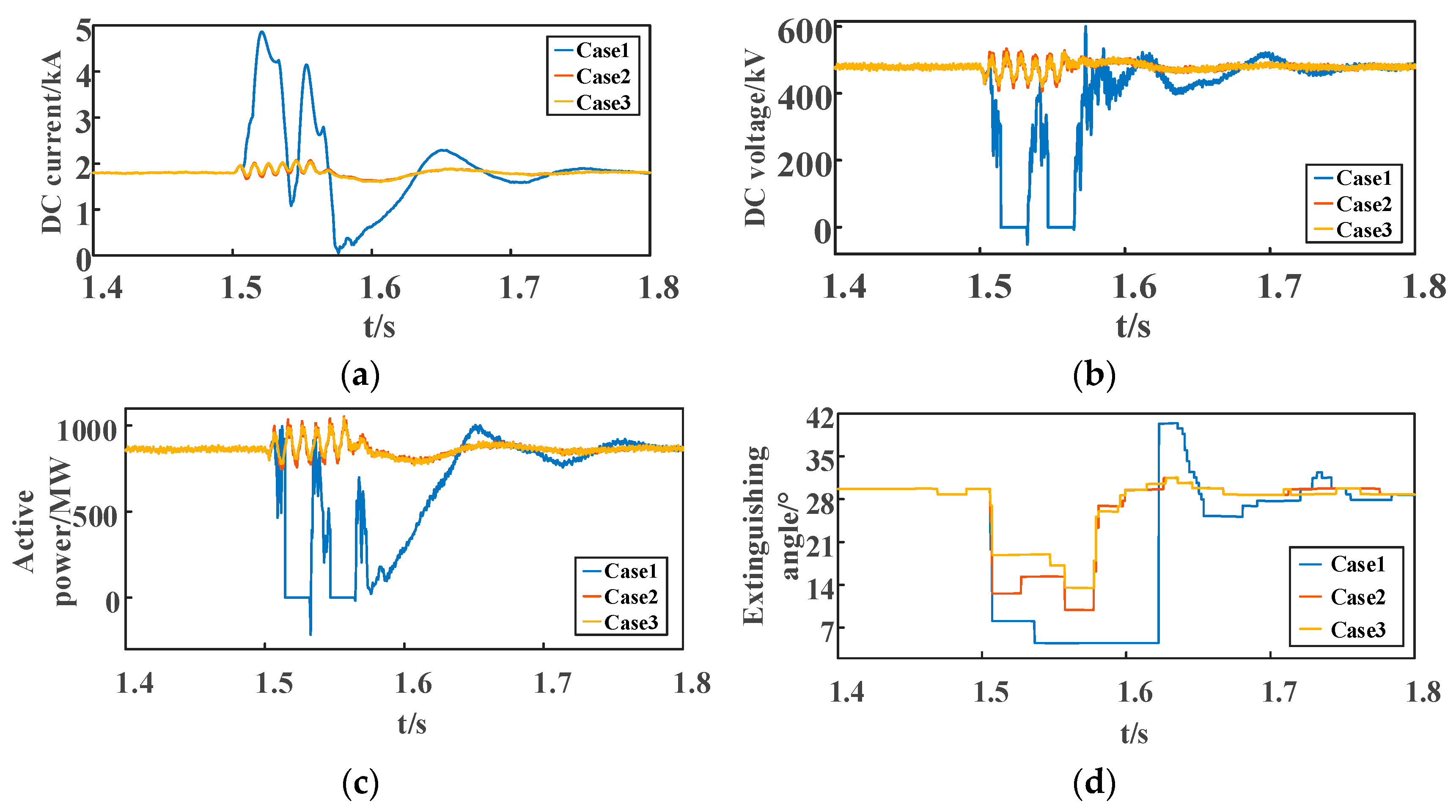
The ground fault inductance was set to 0.25 H, and the simulation results are presented in
Figure 7. It can be seen from
Figure 7 that the DC current on the inverter side of the traditional LCC-HVDC system in Case 1 rises rapidly to 4.86 kA, the DC voltage drops to 0 and even a negative value, and the active power transmission is interrupted and even reversed. Further, the minimum system extinguishing angle reaches 4.5°, and the system commutation fails.
For Case 2, under the control strategy proposed in [
19], the maximum DC current of the LCC-HVDC system increases to 2.07 kA, while the minimum value drops to 1.61 kA; the minimum value of DC voltage reaches 407 kV, while the maximum value increases to 533 kV; and the active power fluctuates between 750 MW and 1050 MW. Further, the minimum value of the system extinguishing angle reaches 9.9°, and the system does not have the problem of CF.
For Case 3, the proposed LCC-HVDC has a maximum DC current of 2.05 kA, while the minimum value drops to 1.60 kA; the minimum value of DC voltage reaches 420 kV, while the maximum value reaches 522 kV; and the active power fluctuates between 770 MW and 1046 MW. The minimum system extinguishing angle is 13.4°, and the system realizes successful commutation.
Compared with Case 1, the proposed LCC-HVDC ensures successful commutation in the event of a fault, stabilizes the transmission power, and increases system reliability. Compared with Case 2, the system has a higher value of minimum system extinguishing angle under the same fault conditions, and has an abundant commutation margin to ensure successful commutation, which improves the reliability and stability of the LCC system.
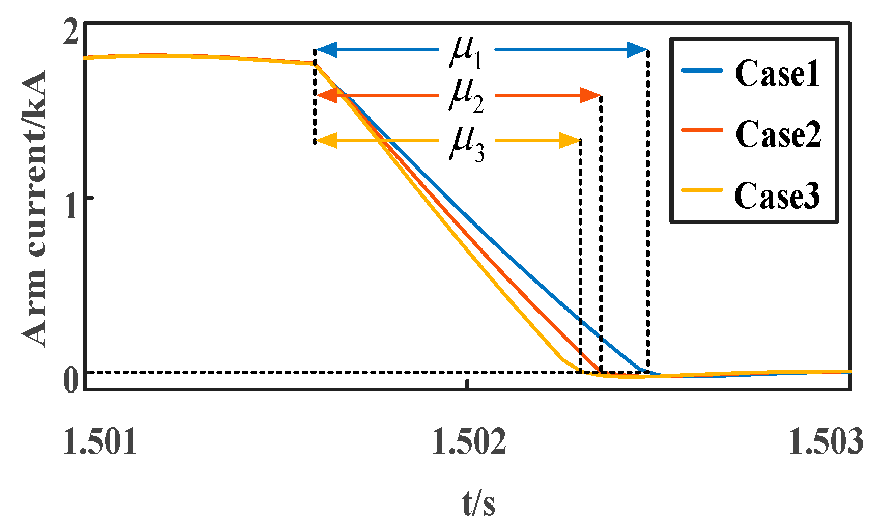
The arm current of the closing arm is shown in
Figure 8. It can be seen that in the first commutation process after a fault occurs, for the closing bridge arm, because there is a freewheeling pathway, the proposed LCC-HVDC system has a faster response speed, which means a smaller commutation overlap angle
μ and a larger commutation margin. Therefore, the proposed strategy has more powerful ability of resisting to CF.
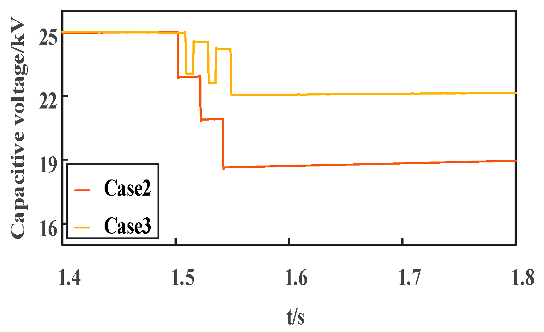
The fluctuations in the sub-module capacitor voltages are illustrated in
Figure 9. For Case 2, under the proposed control strategy, the sub-module is always inserted in the opening arm, and the sub-module capacitor continuously discharges, with its voltage dropping to 18.53 kV during the fault time. If the sub-module capacitor voltage drops too low, the system cannot resist CF. Therefore, accurate calculation of the initial capacitor voltage is critical.
Figure 9 demonstrates that the designed LCC-HVDC control strategy successfully maintains capacitor voltage within stable limits via alternating charge-discharge cycles, unlike the significant voltage drop observed in Case 2. Therefore, the proposed LCC system has a greater commutation margin, which increases the ability of the system to resist CF.


