1. Introduction
Systems with multiple inputs and degrees of freedom are common in everyday life. An underactuated system results when the number of control inputs of the original system is less than the system freedom number [
1,
2,
3,
4,
5,
6,
7,
8,
9]. The benefits of an underactuated system include low weight, low cost, and low energy consumption. When some devices of the fully actuated system fail, the underactuated control method can improve reliability and ensure continuous operation. The underactuated robot is a typical system in an underactuated system. Underactuated robots can be categorized into two cases based on whether or not they are affected by gravity: vertical underactuated robots [
10,
11,
12] and planar underactuated robots [
13,
14,
15]. This paper focuses on planar underactuated robots.
Planar underactuated robots have several potential applications in space research [
16] and deep-sea exploration [
17,
18]. Since deep sea and space are microgravity environments, robots have more advantages than humans in terms of operation and safety when performing some command operations. Therefore, researching this type of system’s control method has enormous practical implications. The motion process of the planar robot is through the control method designed to make the robot arrive from any position in the plane to any position we need. According to prior studies of planar underactuated robots, the nonlinear approximation model is found to be uncontrollable at any equilibrium point during the control process. Therefore, the realization of this kind of robot position control is more complicated and difficult than other robot systems. As a matter of fact, the characteristics of control for the underactuated robot are closely related to the number of links and the passive joint positions. The control characteristics of an underactuated robot will vary depending on the position and number of passive joints. According to whether there is a complete integrable property and constraint relationship between underactuated links, they can be divided into holonomic systems and non-holonomic systems [
19,
20].
Planar 2R underactuated robots are divided into planar Acrobot robots and planar Pendubot robots. In planar Acrobot robots, if the first joint fails or is damaged, it becomes a passive joint. It possesses holonomic characteristics and a relationship defined by angular constraints. Lai [
21] et al. deduced the angular constraint of the link based on integrability, and achieved position control by regulating the active joint with the aid of the angle constraint. In [
22], good position control was achieved by using the method of model reduction and energy attenuation. In [
23], a position control strategy is proposed for the planar Acrobot robot. Under the coupling constraint between the systems, the goal position of the robot is realized by using two stages of control. The planar Pendubot robot, a 2R underactuated robot whose second joint is passive, is a member of the nonholonomic system that is subject to an angular acceleration restriction [
24]. It is challenging to intuitively determine the mathematical connection between these links, which are active and passive due to the intricate nonlinear features of such systems. To accomplish stable control of the system, an open-loop iterative control approach was created by Luca [
25] on account of the nilpotent approximation model. In addition, an innovative optimization technique based on Fourier transform was put forth in [
26] to realize the stability control for planar Pendubot. The above research focuses on planar Acrobot and planar Pendubot. The following is the unified control method. In [
27], the unified control of the planar 2R underactuated robot is studied, and a control strategy that incorporates trajectory planning alongside tracking control is introduced, which successfully realizes the control objectives of the system. For 2R underactuated robots, Wang [
28] proposes a trajectory planning tracking control strategy based on the basis function superposition method and intelligent optimization algorithm, and only relied on the second-order nonholonomic constraints commonly possessed by 2-DOF rotary underactuated robots to achieve unified control of such systems, simulation tests verified the efficacy of the strategy.
Based on the above analysis of previous studies, the research of planar 2R underactuated robots lays a foundation for the control theory research of underactuated robots. Currently, most previous studies have only proposed control methods for robots with specific structures and functions. Due to the uncertainty of passive joint position, it is necessary to explore a unified control strategy for both planar Acrobot and planar Pendubot in order to realize effective control of planar 2R underactuated robots. However, when a joint of a planar full actuated joint fails and becomes a passive joint, if the position of the passive joint cannot be directly determined, the present control methods are relatively simple and the control stability time is longer. Therefore, in order to realize the effective control of the planar 2R underactuated robot, in this case, it is essential to investigate a more simple and general method to realize the unified control strategy of the two robots above.
Based on the above analysis, this paper presents a simple planar 2R underactuated robot control strategy. By optimizing the PD parameters of the controller, the time required for the 2R underactuated robot to stabilize to the ideal state is shortened. The structure of the subsequent chapters of this paper is elaborated from the following aspects: A dynamic model of a planar 2R underactuated robot system is established in
Section 2.1, and the characteristics of the system are described in
Section 2.2. Then, in
Section 3, a PD controller with adjustable parameters is designed. To attain the desired control objective, in
Section 4, the differential evolution algorithm (DEA) [
29] is used to continuously enhance the parameters to obtain the optimal control effect, so as to ensure that each link can best achieve the control objective. Finally, in
Section 5, three sets of simulation experiments with different initial conditions and target conditions are carried out for the 2R underactuated robot Acrobot and Pendubot, respectively, to assess the efficacy and universal applicability of the method.
3. Controller Design
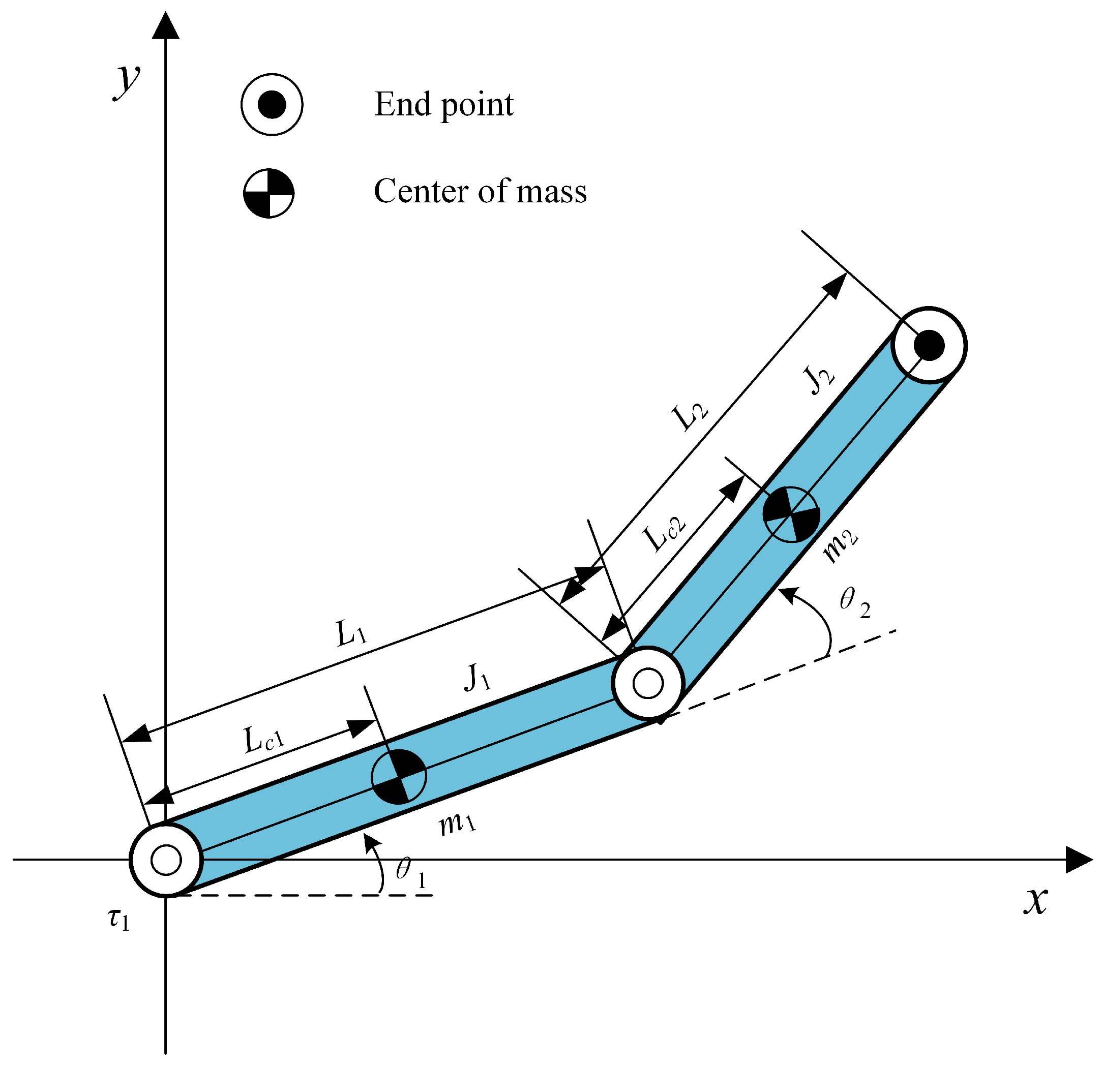
We design a PD controller in this subsection in order to steer all links toward their desired states. Let the
, in which
represent
, the angles of the two links of the robot and
are
, the angular acceleration at the two linking joints. The following state space expression can be further obtained as
In this state space Equation (
7),
The active link’s control goal determines the selection of the Lyapunov function, and it is given in Equation (
10).
where
represents the positive constant, and
;
represents the angular state of the link,
represents the angular target state of the link,
;
represents the angular velocity of the link,
.
Then, the derivative of
is going to be
Therefore, the controller design of the system is as follows
where
,
is the principal diagonal element of the matrix of Equation (
9), which is
and
. Since
is a positive definite matrix, the elements of the principal diagonal are not zero, that is,
is nozero, which effectively avoids the control torque singularity problem.
is divided into
and
, which correspond to the control torque of planar Pendubot and planar Acrobot, respectively.
Bringing Equation (
12) into Equation (
11) gives
When Equation (
12) is substituted for Equation (
7), the system which is closed loop will be
Equation (
14) is a closed-loop control system with a PD controller. It is obvious from Equation (
13) that
is bounded. Then, we define the following conditions
in which
. Any solution
x of Equation (
15) coming from
still remains in
for all
. By setting
as the invariant of Equation (
14), we obtain
Set
,
, then substitute it into Equation (
7) and obtain the following result.
According to the different positions of the passive joints,
can be specifically divided into
and
in Equation (
8). The passive joint is
in the first link, and the passive joint is
in the second link. Substituting Equation (
17) into Equation (
12) obtains
. Then, the maximum invariant set is
According to the LaSalle invariability principle [
31], when Equation (
16) reaches the predetermined control goal, the state of the actuated link is
,
.
Therefore, when the following conditions are satisfied, the linkage of the planar 2R underactuated robot system is controlled to the target state.
where
and
are small positive error coefficients.
According to the above analysis, the underactuated link is still rotating when the actuated link stabilizes to the desired state, and the underactuated link is the one containing the underactuated joint. Therefore, this paper designed a simple PD controller for the actuated link, optimized the controller parameters through DEA, and successfully realized the stability of the whole system.
4. Controller Parameter Optimization
The active link’s control objectives could be achieved by the intended controller because the controller (
12) forces the actuated link to remain stable at its goal position. Therefore, the DEA is used to calculate
and
to guarantee that the unactuated link successfully attains its intended state.
The DEA’s evaluation function, as explained in [
29].
where
, and
.
The following are the steps of the designed controller calculated by DEA.
Process 1: Random initialization of and .
Process 2: Submit
and
into Equations (
12) and (
5). Then, calculate
and
by means of numerically integrating Equation (
6) according to
,
and
,
,
, and
.
Process 3: If h is less than (a tiny positive constant), the optimization operation is completed. The result of the promotion are and . If not, the program moves on to the next phase.
Process 4: Update and through mutation, crossover, and selection procedures by using (mutation factor) and (crossed factor). The procedure then turns to Process 2.
The basic operation flow of DEA is shown in
Figure 2.
Based on the optimized controller parameters and , the link controller can be determined, and then the initial and target state parameters can be set to verify the designed controller by simulation.
5. Simulations
In this section, the proposed control strategy is verified by Matlab simulation, and three sets of simulations are carried out on the plane Acrobat and plane Pendubot for a planar 2R underactuated robot under different initial and target states, respectively, to assess the efficacy of the proposed control strategy. We choose the same length, weight, and moment of inertia for both links.
Table 1 shows the unified parameters of the planar 2R underactuated robot model.
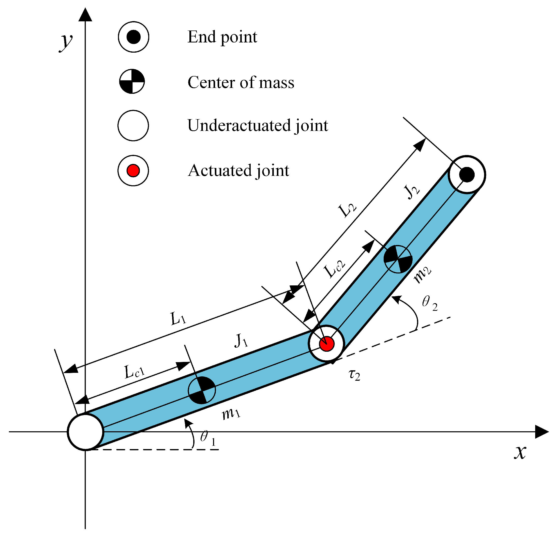
5.1. The Simulation for Planar Acrobot
When the first link fails or is damaged, the planar 2R underactuated robot has underactuated characteristics. In this case, the main drive is the second link, and torque is applied to link 2, i.e.,
. How to use the motion of the second actuated link to control the first link to stabilize the target state is a problem that the simulation experiment must take into account. The model structure is transformed into a planar underactuated robot Acrobot. The converted Acrobot model is shown in
Figure 3.
Therefore, we consider that we will first move the second link to the target state under the action of torque. At the same time, according to the above constraints of the planar Acrobot underactuated robot, under the action of a PD controller, the appropriate parameters are optimized to control the first underactuated connecting rod to move to the target state and finally realize the stability control of the whole planar Acrobot.
5.1.1. Simulation Result 1 for Planar Acrobot
The parameters of the DEA are selected as follows: maximum number of iterations
= 100, the
is generally used as the termination condition of the evolutionary process; population number
N = 50, the greater the population number, the greater the probability of obtaining the optimal solution, but the calculation time is longer; mutation factor
= 0.5, the mutation factor
is an important parameter for controlling population diversity and convergence; crossover factor
= 0.7, the crossover factor
can control the degree of participation of each dimension of the individual parameters in the crossover, as well as the balance of global and local search capabilities;
= 0.005,
is used as the judgment threshold for the final optimization success. DEA is used to control parameters calculated and optimized in Equation (
12) so that it can attain optimal control efficacy on the planar Acrobot. The results of parameter optimization are as follows
The initial and target states of our chosen simulation 1 are shown in Equation (
22).
where
,
,
,
represent the starting angle and desired angle of the first link and the second link, respectively, and
,
,
,
represent the initial angular velocity and target angular velocity of the two links, respectively.
The control of planar Acrobot has achieved the target shown in the simulation results 1, and each state variable is primly convergent to the predetermined value. As shown in
Figure 4a,b, both the angle and angular velocity of the two links converge steadily from the initial state set by Equation (
22) to the target state.
Figure 4c shows the torque variation of the second actuated link.
As can be seen from the
Figure 4, the planar Acrobot has reached the target state and remained stable before
t = 5 s, the maximum angular velocity does not exceed
rad/s, and the torque range is maintained at
. The control strategy has good rapidity and system stability.
5.1.2. Simulation Result 2 for Planar Acrobot
Under the condition that the algorithm parameters remain unchanged, we transform different starting conditions and desired condition parameters to continue the optimization. DEA parameters are as follows: maximum number of iterations
= 100, population number
N = 50, mutation factor
= 0.3, crossover factor
= 0.7, convergence judgment threshold
= 0.005. The optimization parameters of simulation result 2 are shown as follows.
In simulation result 2, the starting state and the desired state are
As shown in
Figure 5a,b, both the angle and angular velocity of the two links converge steadily from the initial state set by Equation (
24) to the target state.
Figure 5c shows the torque variation of the second actuated link. The planar Acrobot before
t = 4 s achieves the target state and maintains stability, the maximum absolute angular speed does not exceed
= 10 rad/s, the value of the torque is still maintained in the range of
, and planar Acrobot fast stability control requirements are achieved.
5.1.3. Simulation Result 3 for Planar Acrobot
To assess the validity of the suggested control strategy, we set up a set of simulations, set state parameters, and optimized PD controller parameters. DEA parameters are as follows: maximum number of iterations
= 100, population number
N = 50, mutation factor
= 0.3, crossover factor
= 0.8, convergence judgment threshold
= 0.005. The parameters of simulation result 3 are
In simulation 3, the starting and desired states of the planar Acrobot are
As shown in
Figure 6a,b, both the angle and angular velocity of the two links converge steadily from the initial state set by Equation (
26) to the target state.
Figure 6c shows the torque variation of the second actuated link. The final results indicate that the control method successfully converges to the target state within
t = 3 s, the angular velocity range is
rad/s, and the range of torque is maintained at
. The control goal can still be achieved.
In simulations 2 and 3 of the planar Acrobot, we set different parameters and different target states, but in the end, it is ideal in terms of speed and stability. In addition, compared with reference [
27], this method is simpler and can control the target state quickly without the need for trajectory planning.
5.2. The Simulation for Planar Pendubot
When the second link of the planar 2R underactuated robot fails or is damaged, then the model has underactuated characteristics, and the model structure is transformed into the planar Pendubot underactuated robot. The specific structure is shown in
Figure 7, and simulation experiments are carried out on the planar Pendubot model.
Also, three sets of different starting state parameters and desired state parameters are selected to carry out simulation on the planar Pendubot underactuated robot. For the planar Pendubot underactuated robot model, in this case, the main driver is the first link, and torque is applied to link . The first link moves to the target state under the action of torque. At the same time, according to the constraint relation of the planar Pendubot underactuated robot, the second underactuated link is controlled to move to the desired state, and the stability control of the entire planar Pendubot is finally realized.
5.2.1. Simulation Result 1 for Planar Pendubot
Similarly, the parameters of the DEA are selected as follows: maximum number of iterations
= 100, population number
N = 50, mutation factor
= 0.5, crossover factor
= 0.7, convergence judgment threshold
= 0.005. Using DEA for the controller parameters, we calculated and optimized Equation (
12), so that it can attain optimal control efficacy on the planar Pendubot. The results of parameter optimization are as follows
In simulation result 1, the starting state and the desired state are
The control of planar Pendubot reaches the target shown in simulation results 1, and each state variable basically converges to the predetermined value. As shown in
Figure 8a,b, both the angle and angular velocity of the two links converge steadily from the initial state set by Equation (
28) to the target state.
Figure 8c shows the control torque variation of the first link. Before
t = 5 s, the planar Pendubot has reached the target state and maintained stability. The angular velocity range is
, and the control torque range is within
, which meets the control requirements of the system. Therefore, this control strategy has good rapidity and system stability for planar Pendubot.
5.2.2. Simulation Result 2 for Planar Pendubot
In the same case that the algorithm parameters are unchanged, different starting state parameters and desired state parameters are transformed to continue the optimization. DEA parameters are as follows: maximum number of iterations
= 100, population number
N = 50, mutation factor
= 0.3, crossover factor
= 0.7, convergence judgment threshold
= 0.005. Optimization parameters of simulation result 2 are as follows:
In simulation result 2, the starting state and the desired state are
The planar Pendubot control achieves the target shown in simulation result 2, and each state variable basically converges to the predetermined value. As shown in
Figure 9a,b, both the angle and angular velocity of the two links converge steadily from the initial state set by Equation (
30) to the target state.
Figure 9c shows the control torque variation of the first link. Under the second set of state parameters, the changes of state variables of the planar Pendubot double links mechanism and the changes of torque of the movable link mechanism are analyzed. Before
t = 4 s, the planar Pendubot has reached the target state and remains stable. The angular velocity range is
, and the control torque range is within
, which reaches the control goal of the system.
5.2.3. Simulation Result 3 for Planar Pendubot
To confirm the general applicability of the strategy to the planar Pendubot underactuated robot, the third set of simulation experiments was conducted, and the following state parameters were selected to optimize the PD controller by differential evolution algorithms. DEA parameters are as follows: maximum number of iterations
= 100, population number
N = 50, mutation factor
= 0.3, crossover factor
= 0.8, convergence judgment threshold
= 0.005. The parameters of simulation result 3 are
In simulation result 3, the initial and target states of each state variable of the planar Pendubot are
Under the third set of state parameters, the planar Pendubot control reaches the target shown in the simulation results, and each state variable basically converges to the predetermined value. As shown in
Figure 10a,b, both the angle and angular velocity of the two links converge steadily from the initial state set by Equation (
32) to the target state.
Figure 10c shows the control torque variation of the first link. Before
t = 3 s, the planar Pendubot has reached the target state and remains stable. The angular velocity range is
, and the control torque range is within
.
In simulations 2 and 3 of planar Pendubot, different parameters and different target states are set, and the simulation results indicate that the results are good in terms of speed and stability. In addition, compared with reference [
27], this method is simpler and can control the target state quickly without the need for trajectory planning.
5.3. Analysis of Simulation Results
For planar Arcobot and planar Pendubot underactuated robots, three groups of different state parameters were selected to design a simple PD controller, and the parameters of the PD controller were successfully optimized by the differential evolution algorithm. Different mutation factor
and crossover factor
parameters are set to verify the effect on the convergence rate and show the sensitivity of the algorithm to the parameters. The proposed control strategy’s effectiveness was validated through simulation. The following are three different groups of parameter indicators in the control process of planar Arcobot and planar Pendubot underactuated robots, as shown in
Table 2 and
Table 3.
The results of
Table 2 and
Table 3 show that the rotation angle of all the links in the simulation successfully converges, and the stable control of the target state is achieved. The change in angular velocity is proportional to the change in torque. The larger the variation factor pm, the slower the convergence rate and the increased stabilization time required. The larger the crossover factor pc, the faster the convergence rate, and the less time it takes to reach stability.
In optimization design, DEA has the following main characteristics compared with traditional optimization methods:
(1) The DEA searches from a group of multiple points rather than from a single point, which is the main reason why it can find the overall optimal solution with a high probability;
(2) The evolutionary criterion of DEA is based on adaptive information and does not need to rely on other auxiliary information (such as requiring the function to be derivable or continuous), which greatly expands its application scope;
(3) DEA has inherent parallelism, which makes it very suitable for large-scale parallel distributed processing and reduces the overhead of inter-cost;
(4) DEA adopts probabilistic transition rules and does not require deterministic rules.
6. Conclusions
A simple PD control strategy is proposed for a planar 2R underactuated robot. The appropriate controller parameters are obtained by DEA, and the PD controller makes the whole system move from the initial state to the target state under the actuated link. Finally, the effectiveness and universality of the proposed strategy are verified by simulation, and the potential relationship between angular velocity variation and torque magnitude, as well as the influence of mutation factor and crossover factor on the convergence rate, are obtained.
In future work, we will use this simple and effective control method to deal with multi-degrees of freedom underactuated robots, cluster underactuated robot control, and multi-passive joint underactuated robots. This control method expands the theory of nonlinear control and underactuated control and provides a theoretical basis and reference for subsequent research.


