Abstract
This work introduces two cooperative dielectric elastomer actuator (DEA) array designs, enabling comparison between a fully soft, wearable-oriented system and a rigid, high-performance platform. The soft silicone-based array achieves strokes up to 1.9 mm and maintains 44% displacement under strong bending, demonstrating suitability for haptic feedback in wearable applications. The rigid prototype, based on thermoformed buckling beams, provides strokes up to 2.8 mm, reduced hysteresis, improved stability, and reproducible fabrication, while allowing fine-tuning of preload conditions. Experiments revealed frequency-dependent coupling, enabling stimulation of defective actuators via neighboring elements and amplification of single-element strokes through cooperative excitation. Furthermore, self-sensing effects were exploited for error detection. These results underline the potential of DEA arrays for decentralized control, fault-tolerant actuation, and future applications in soft robotics and wearable systems.
1. Introduction
The term cooperative system refers to devices in which several, mostly independent, units work together to perform complex tasks, leveraging on decentralized communication and distributed control approach. Such paradigm offers a number of potential advantages, such as increased failure or fault tolerance of the single units, lower computing costs, and improved flexibility in the system layout as there is no need to create a central node connected to all units. Cooperative systems usually comprise a hardware part (agents/entities to be controlled), communication paradigms among these agents [1], and a control strategy, which uses the communicated information to determine the appropriate actions to fulfill the task [2]. Examples of research areas in which cooperative systems have found successful applications include smart grids with decentralized and non-hierarchal voltage regulation [1,3], as well as communication in sensor networks, multi-robot systems, autonomous connected vehicles, or unmanned aerial vehicles [4,5,6,7]. Further examples include conveyor systems [8,9,10], position control for two-dimensional displacements [11], crawling robots [12], and reconfigurable structures or fluid flow control [13,14] that are based on arrays of multiple actuators. Most of these approaches require a visual feedback system which is processed in real time by a central control to perform a global control task. This type of architecture, however, is not exploiting the full potential of a cooperative system, in which a decentralized control is considered as more favorable in terms of both simplified measurement hardware and resilience to sensor failures.
An approach to overcome this issue is using actuator systems based on smart materials. This type of material can offer new possibilities to implement a novel generation of cooperative systems, due to their inherent ability to function simultaneously as an actuator and a sensor, thus making external probes or feedback systems obsolete and further offering great potential for miniaturization and integration. To date, dielectric elastomers (DEs) represent one of the most commonly used smart materials in mechatronic applications. DEs are based on a thin and highly stretchable polymeric membrane that is coated with a likewise stretchable conductive material on both sides, resulting in a deformable capacitor. Researchers have shown various actuator applications based on DEs, ranging from classical industrial devices like pumps or valves [15,16] to contemporary topics like soft robots and wearable devices [17,18,19,20,21,22,23]. The latter examples show the great potential of this technology for human-interaction applications, due to its overall low stiffness and weight. Several DE-based cooperative actuator systems have also been proposed, such as refreshable Braille displays using pressured air or hydrostatic biasing [24,25], fluidic devices such as micro-mixers and peristaltic pumps [26,27], micro lenses [28], cell-stretchers [29,30] or haptic devices that are in direct skin contact [31,32]. Combining the actuation and sensing capabilities of DEs makes it possible to develop self-sensing smart material systems, offering innovative possibilities for a new generation of autonomous and cooperative devices. As an example, self-sensing allows us to develop compact cooperative DE systems in which each active unit can also simultaneously record data on the status of the overall system [33]. However, current DE-based cooperative systems usually do not utilize the self-sensing effect. Therefore, they do not exploit the full potential of DEs as a smart material. The aim of this work is to develop a cooperative actuator array that offers new possibilities for using self-sensing. The main difference from previously presented DE-actuator systems is that all the actuator elements in this work are integrated into a single silicone membrane. This means that all the actuators are mechanically coupled to each other. This coupling means that the actuation of a single element influences the physical state of all mechanically coupled elements, opening new possibilities in terms of cooperative control strategies. For instance, inactive actuator elements can be activated by controlling neighboring elements specifically, or the self-sensing effect can be employed to verify whether a stimulated actuator is intact or blocked.
The focus of this study is on the hardware implementation and the analysis of electromechanical coupling effects. While parallel research efforts address FEM- or model-based simulations of coupled DEAs [34], these aspects are not considered in detail here, as their complexity warrants a separate and dedicated investigation.
In this paper, we present novel types of DE-driven cooperative actuator systems based on two different types of fully polymeric arrays with mechanically coupled units, both using so-called non-linear biasing elements to drastically increase the stroke output of the individual actuator elements. Firstly, we introduce a fully polymeric and flexible DE-array with a one-by-three layout, almost entirely based on silicone materials which uses silicone-based biasing elements. By using only polymeric materials for the structure, the whole array is made soft and flexible and thus shows suitability to be used in wearable haptic devices or in interactive soft robots. Secondly, we present an improved and more robust version of this array, by designing a more rigid system that offers more possibilities for subsequent fine-tuning, which is based on thermoformed, polymeric biasing systems. Compared to the first-generation array, the improved one exhibits a higher stroke output and a stronger mechanical coupling among the actuation units, while offering more options for a subsequent performance tuning. For both arrays, we investigate the mechanical coupling and the resulting possibilities for cooperative actuation and demonstrate that defective actuators can be stimulated via neighboring elements and that the stroke of individual actuators can be amplified by selectively exciting adjacent units. Additionally, we characterize the performance of the flexible array while being heavily deformed, proving that this type of system can be effectively used in soft wearable devices.
The remainder of the paper is structured as follows. Section 2 focuses on the basics of DE-actuators, by explaining the general functionality as well as the details of the used biasing systems and of the two presented array versions. Section 3 starts with an explanation of the used experimental setup followed by a detailed characterization of both array versions, which focuses on their performance and the effects of the mechanical coupling on cooperative control strategies. In Section 4, a final conclusion of the conducted experiments and their results is given.
2. Materials and Methods
2.1. Dielectric Elastomer Actuators
The two most frequently used materials used for DE-actuators (DEAs) are silicone and acrylic elastomers. Silicone is characterized by a shorter response time and is more stable in a larger temperature range, due to its overall lower viscosity, compared to acrylics which can sustain a significantly larger deformation and have a higher dielectric constant [35]. The electrode material which is deposited on both sides of the membrane is usually based on carbon [36], it but can also be made of corrugated thin metal films [37]. All DE devices presented in this work are based on a silicone elastomer with thicknesses of 50 and 40 µm with screen-printed carbon-based electrodes.
The functional principle of DEAs is based on the electrostatic attraction between charges on the two electrodes, combined with the electrostatic repulsion between charges on the same electrode, in response to an applied voltage difference. Due to this effect, the elastic dielectric between the electrodes is thinned and increasing in surface area simultaneously. Both membrane thinning and area expansion can be used for actuation purposes [38].
To increase the actuation stroke, the DE membrane is typically coupled with a pre-loaded biasing mechanism. Depending on the envisioned application, several biasing mechanisms have been investigated, ranging from simple masses [39], linear springs [40], or pressurized air [41] to more complex, non-linear systems like buckled beams [42], attracting magnets [43], or polymer-based buckling domes [44]. The non-linear biasing springs (NBS) are especially suitable for DEAs, as they result in a higher stroke compared to springs, masses, or pressurized air. In order to understand how the non-linearity helps to increase the DEA system stroke output, Figure 1 schematically displays the force–displacement characteristics of a membrane DE (low- and high-voltage are depicted in blue and red, respectively) together with an ideally designed non-linear biasing element and compares it to the force–displacement characteristics of the same DE using a linear biasing spring. The horizontal distance between the intersections of the biasing curve with the two characterizing DE graphs represents the maximal possible stroke output of the specific combination of DE and biasing element. Such a graphical approach is also used in this work as a state-of-the-art design solution to optimize the biasing element for a given DE. Figure 1 illustrates the importance of a precisely designed biasing curve for the design of a high-performance actuator and schematically shows how stroke and force-output can differ using a linear spring.
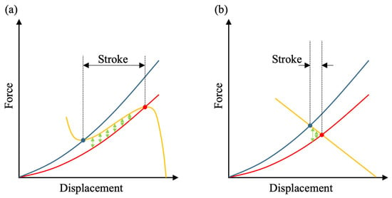
Figure 1.
(a) Schematic of the force–displacement diagram of a high-performing DE-actuator (blue: low-voltage, red: high-voltage) based on a negative-rate biasing spring (orange). The horizontal distance between the intersection points represents the theoretical stroke, while the green arrows show the maximal output force of the actuator depending on its position. (b) Schematic of the force–displacement diagram of a low-performing DE-actuator using a linear spring.
2.2. Polymeric Biasing Elements
Two different polymer-based preload mechanisms are used in this work, both representing a physical implementation of the non-linear biasing element in Figure 1a, with the purpose of designing high-stroke actuator arrays. For the first version of the actuator system, three-dimensional domes made of silicone are used, similarly to the ones previously investigated in [44]. Figure 2a shows a cross-sectional CAD view of a single biasing dome manufactured by casting an RTV silicone into a multi-part mold.
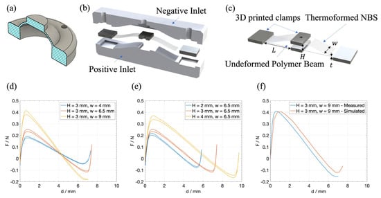
Figure 2.
(a) Cross-sectional CAD view of a cast silicone dome, previously described and investigated in [44]. (b) Rendered cross-sectional view of a thermoformed NBS together with the shaping inlets. (c) Rendered version of an undeformed and thermoformed polymer NBS showing the changeable geometric parameters. (d) Force–displacement curves of three different thermoformed NBS having the same height (3 mm) but different widths (4 mm, 6.5 mm, and 9 mm). (e) Force–displacement curves of three different thermoformed NBS’s having the same width (6.5 mm) but different heights (2 mm, 3 mm and 4 mm). (f) The same measured curve as in (d) (yellow line, without hysteresis) together with the corresponding FEM-simulated curve.
Previous investigations have shown that the type of biasing can severely affect the long-term stability of the resulting actuator. In [45], the creep effect of silicone-based biasing elements was compared to that of PET-based elements, showing that silicone-based elements are less suitable for long-term stable systems or require a longer training period before use in DEAs. Thus, for the second version, a new design based on thermally reshaped buckling beams, also shown in [45], is used. To this end, strips with a specific geometry are cut out of a thin polymer film (PEEK, LITE-K, 100 µm, 125 µm or 150 µm). The PEEK material was chosen for its superior mechanical characteristics, which account for the resulting actuator’s improved long-term stability. However, this work focuses primarily on the electromechanical coupling of DEAs on a shared membrane rather than on long-term investigations. Therefore, no experiments have been conducted that focus on the long-term effects of DEAs. For a better handling and mounting, clamps are printed around the ends and in the middle of the strip using 3D printing. For thermal forming, the strips prepared in this way are placed in a 3D-printed, shaping inlet and heated to a temperature above the glass transition temperature (180 °C). Once the temperature has been reached, the desired shape is embossed into the strip by pressing a second inlet with a complementary geometry. If the pressure is kept until the strip cools down below the glass transition temperature, it retains the embossed structure even without the shaping inlets. The basic process of thermoforming is pictured in Figure 2b. To prevent the film from stretching and thus thinning, the length of the area to be thermoformed is selected so that it corresponds to the arc length of the final geometry of the biasing element. The tunable geometrical parameters (height H, width w, length L, thickness t) are shown in Figure 2c, where an undeformed and thermoformed polymer beam is shown in a rendered version. The general shape was chosen according to the findings of [46] and were tuned in order to match the DE-curves as shown in Figure 1a. In order to tune the resulting force–displacement curve of the element, several of these non-linear springs with different geometries were manufactured and characterized. Figure 2d,e show measured force–displacement curves of different beam geometries with L = 12.5 mm and t = 100 µm and illustrate how the overall shape of the graph varies when changing w and H, while keeping all other parameters constant. In this work, parameter L was held constant at L = 12.5 mm. This value is close to the maximum applicable value for L which is constrained by the overall planned array geometry. Using shorter beams usually leads to a lower maximum possible height, which results in a smaller region of negative slope in the force–displacement curve and thus limits maximum stroke of the actuator; this is the reason why a large value for L is a reasonable choice for our application. By using a model-based approach similar to the one presented in [47], these experimental results were used to train a finite element model, which was then used to simulate various biasing element geometries to finally determine an optimized beam geometry for a given DE membrane. In Figure 2f, the simulated force–displacement curve of a beam having the same geometry as in Figure 2d (yellow curve) is shown, together with the measured curve. The deviations between the actual measurement and the simulation are due to manufacturing tolerances during the manufacturing process. The most important influences which lead to these tolerances are as follows:
- Cutting the beam using a cutting plotter (Cricut Maker 3), whose tolerance influences the width w of the beam;
- Printing the clamps using 3D printing (FDM printer), whose tolerances determine the free length L of the beam;
- The shaping, also 3D-printed (SLA printer) inlets for the forming process, which, in particular, determine the resulting height H of the spring element;
- The 3D-printed holder into which the spring elements are pressed during the measurement. These can cause an additional change in the compression of the spring element, and therefore additionally influence L and H.
The simulation tool can be used to find an initial beam geometry that, in the thermoformed state, has a force–displacement curve which is close to the desired curve and matches the characteristic of a given DE element for stroke maximization (cf. Figure 1). By using a heuristic approach only for fine-tuning the geometry, it is possible to find a suitable NBS geometry with very few iterations using the simulation tool for an initial geometry.
2.3. Cooperative DEA-Arrays
To enable a direct comparison between fundamentally different system designs, two DEA array prototypes are introduced. The first version represents a fully soft and flexible architecture, optimized for close-to-body interaction and wearable applications such as haptic feedback, but with somewhat lower actuation performance. In contrast, the second version follows a rigid platform approach, which sacrifices flexibility in favor of significantly improved mechanical performance and higher stroke output. This dual strategy allows the evaluation of cooperative actuation in both highly compliant, wearable-oriented arrays and in more powerful, hardware-optimized systems.
2.3.1. Version 1 (Flexible Approach)
Version 1 of the cooperative array basically consists of two main parts, namely the silicone membrane (thickness of 50 µm) with three electrically independent but mechanically coupled DE elements and an array of three silicone-based domes. The latter is manufactured in a monolithic fashion as initially described in [44], while the geometry of each dome is based on the model approach from [47] together with empirical adjustments based on force–displacement measurements. Flexible PCBs made of polyimide (PI) were used together with a conductive ink based on silicone and silver to ensure reliable electrical contacting between the DE electrode and an electrical terminal. A frame of double-sided adhesive tape (NITTO P905) is used to determine the outer dimensions of the DE membrane (100 mm × 50 mm), as well as to mechanically connect the membrane to the biasing array without losing the flexibility of the overall system. Three-dimensional printed connecting pieces are placed on the top of the individual domes, ensuring a mechanical connection with their respective DE elements. The diameter of the upper round surface which is in contact with the DE membrane determines the force–displacement curve of the DE elements. All dimensions of the arrays and the used biasing elements can be found in Appendix A. The dimensions of the printed electrodes are displayed in Figure 3a, while a picture of a completely assembled array is shown in Figure 3b. The resulting force–displacement curves of the domes with the respective curves of the DE elements are shown in Figure 3c,d.
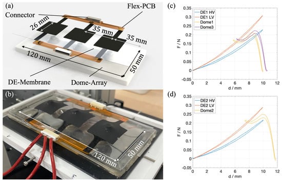
Figure 3.
(a) Rendered explosion view of the flexible DEA array, based on the silicone dome-array. (b) Picture of an assembled demonstrator. (c) Measured force–displacement graph of DE1 (one outer element in the DE-array) together with ‘Dome1’ and ‘Dome3’ (both outer elements in the dome-array). (d) Measured force–displacement graph of DE2 (center element in the DE-array) together with ‘Dome2’ (center element in the dome-array).
2.3.2. Version 2 (Rigid Approach)
The second version of the DEA array was designed with robustness as the main design objective. This approach was chosen to be more flexible both in the structure of the system and in subsequent optimization. In particular, it was designed so that each spring element can be replaced individually and its preload adjusted separately. In contrast to version 1, it uses a different, thinner silicone membrane (40 µm) and is based on a rigid, 3D-printed polymer frame and is therefore significantly less flexible. This frame serves, on the one hand, as a holder for the spring elements, which are pressed into corresponding mounts from below, and, on the other hand, as a carrier for the DE membrane including a flexible circuit board for contacting, which is also glued to the frame with double-sided adhesive tape. The bending beam springs described above were used for this version of the array. An M2 screw is screwed into the middle clamp from below, for subsequent adjustment of the preload of each individual element. A 3D-printed plunger is attached to the end of each screw, which acts as an interface between the DE membrane and the spring element. As the diameter of this plunger influences the force–displacement characteristics of the DE elements, its adjustment provides a further subsequent setting option. Figure 4 shows the explosion view of the system including the most important geometries (a), a picture of an assembled demonstrator (b), and the measured high and low voltage force–displacement curves of DE1 together with the curves of the used biasing elements (c).
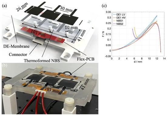
Figure 4.
(a) Rendered explosion view of the rigid DEA array, based on thermoformed biasing elements. (b) Picture of an assembled demonstrator. (c) Measured force–displacement graph of DE1 together with NBS1 and NBS2.
3. Results and Discussion
3.1. Experimental Setup
The same test bench was used to test both arrays. The focus of the investigation was on the performance of the individual actuator elements as well as their mutual influence. A high-voltage amplifier (Hivolt HA51U 3P5, hivolt.de GmbH & Co. KG, Hamburg, Germany), which is controlled via an NI LabVIEW module, was used to electrically excite the actuators. To measure the stroke response of a single DEA, a laser sensor (Keyence LK-G78, KEYENCE DEUTSCHLAND GmbH, Frankfurt am Main, Germany) was used, which is mounted vertically above the actuator to be measured. A line laser (Wenglor MLSL123, wenglor sensoric elektronische Geräte GmbH, Tettnang, Germany) was used to measure a two-dimensional profile of the entire array. An LCR meter (Rohde & Schwarz, HM8118, Rohde & Schwarz GmbH & Co. KG, München, Germany) was used to record the capacitance to determine the self-sensing capabilities of the system, when neighboring elements are actuated. Figure 5 schematically shows the used setup. All components are controlled by NI modules via a LabVIEW host program.
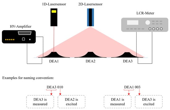
Figure 5.
Schematics of the used experimental setup and two examples to explain the naming convention.
3.2. Flexible DEA Array Characterization
3.2.1. Quasi-Static Characterization
The array is characterized in two different ways, i.e., quasi-statically and dynamically. In the first step, the stroke of the individual actuator elements is measured while an actuation voltage signal is applied. For this purpose, a unipolar sinusoidal signal with a maximum amplitude of 3000 V is applied to the respective electrode, while the resulting stroke is measured using the 1D-laser sensor. Figure 6a shows the resulting laser signals over the applied voltage for each one of the three elements. A frequency of 0.1 Hz is set for the sinusoidal voltage signal, to investigate the quasi-static stroke of the actuator elements. The effect of the mechanical coupling on non-actuated elements is also investigated. For this purpose, a voltage of 3000 V is applied to one of the three actuator elements while the stroke of the non-actuated elements is measured. In the resulting graphs, the first label “DEAi” indicates the i-th element being measured, while the following triplet of numbers describes the voltage configuration. For example, “DEA1 001” means that the first actuator element was measured using a laser sensor and the voltage signal was only applied to element 3. This naming convention is illustrated again in Figure 5. In the following experiments, the frequency of the sinusoidal excitation signal was changed to 0.5 Hz, 1 Hz, and 5 Hz, while the stroke of the excited actuator element was measured. The results are depicted in Figure 6b. It clearly shows how the stroke is decreasing with an increasing excitation frequency. The same experimental setup is also used to measure the stroke of the neighboring elements. Figure 6c shows the resulting stroke of DEA1, while DEA3 was actuated with different excitation frequencies. For the quasi-static case, where f = 0.1 Hz, DEA1 is showing a small stroke of ~0.07 mm while the stroke of DEA3 reaches ~1.9 mm. With f = 5 Hz, the resulting stroke in DEA3 shows a purely negative stroke of around −0.13 mm, thus, it is moving downwards while DEA1 shows an upwards stroke of ~1.1 mm. The measured strokes of DEA1 for f = 1 Hz and f = 0.5 Hz show both behaviors though in both cases, the stroke starts in the negative direction and turns positive during the actuation of DEA3. However, in both scenarios, the maximum positive stroke reaches higher values than in the quasi-static experiment with f = 0.1 Hz. In [48], it was shown that a static pre-loading of one actuator element results in a softening of the force–displacement characteristic of the neighboring elements. This explains the positive stroke of the non-actuated DEA1 in the quasi-static case. The negative stroke with higher excitation frequencies can be related to viscoelastic effects in the silicone membrane. Due to the fast response of the actuated DEA3, the overall membrane is expected to stiffen, thus pushing DEA1 down, which results in the negative stroke. For f = 5 Hz, the excitation signal is cut off by the viscoelastic bandwidth of the material response, which explains the purely negative stroke. At f = 5 Hz and f = 1 Hz, the upward motion appears to be fast enough to cause a temporary stiffening of the membrane and thus a negative stroke, but the overall excitation duration is long enough to allow the viscoelastic effects to decay, resulting in a positive stroke later during the excitation. All measured stroke values for all quasi-static excitation cases are listed in Table 1.
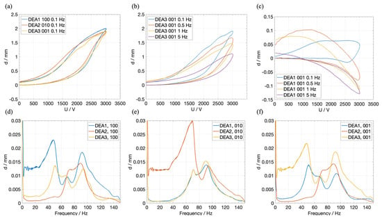
Figure 6.
(a) Quasi-static stroke response of each DEA element on a 3000 V sinusoidal voltage signal with a frequency of 0.1 Hz. (b) Stroke response of DEA3 on four different excitation frequencies (0.1 Hz, 0.5 Hz, 1 Hz, 5 Hz). (c) Stroke response of DEA1, when DEA3 is excited with four different excitation frequencies. (d) FFT of the stroke response of all three DEAs, when only DEA1 is excited with a sinusoidal sweep signal. (e) Same as (d), but only DEA2 is excited. (f) Same as (d), but only DEA3 is excited.

Table 1.
Quasi-static displacements of the individual actuators of the flexible array.
3.2.2. Frequency Sweep Characterization
In subsequent experiments, the frequency-dependent coupling among the actuator elements was investigated. Each dielectric elastomer actuator (DEA) was driven sequentially with a sinusoidal voltage sweep of 3000 V amplitude, ranging from 1 Hz to 150 Hz over 15 s. The resulting stroke of the actuated element and both neighboring elements—moving only due to mechanical coupling via the membrane—was recorded, yielding three stroke measurements per excitation. The time-domain data were transformed into the frequency domain using MATLAB’s FFT algorithm (MATLAB_R2022a).
Figure 6d–f show the corresponding frequency responses for the three excitation cases (100, 010, 001). Owing to the symmetric design of the DEA array, cases 100 (Figure 6d) and 001 (Figure 6f) produce mirrored responses, with distinct resonance peaks at 47 Hz and 90 Hz for the actuated elements (DEA1 and DEA3, respectively). The opposite elements exhibit nearly identical responses, slightly shifted by 3 Hz and 1.5 Hz for the first and second peaks, respectively, and with a slightly reduced amplitude. A smaller resonance at 70 Hz is also observed in the actuated element and, more strongly, in the opposite element and more prominently in DEA2. This phenomenon unveils a unique coupling-induced behavior, wherein an unactuated element can be excited to higher deflections by actively driving one of its neighboring elements.
DEA2 does not respond to the first resonance frequency at 47 Hz but shows a pronounced peak at 70 Hz (which can be passively induced by exciting either DEA1 or DEA3 at that frequency) and a weaker one near 90 Hz. For the excitation case 010 (Figure 6e), DEA2 exhibits a clear resonance at 70 Hz, which is also present in DEA1 and DEA3, as well as a secondary peak at 95 Hz that coincides with the 90 Hz resonance of the outer actuators.
Overall, these results reveal a complex electromechanical coupling among the three actuator elements. Specific actuation behaviors in one element can be triggered by exciting another, suggesting that in larger arrays, defective actuators could be stimulated indirectly via their neighbors. This coupling mechanism could also be exploited to enhance or amplify individual actuators through targeted frequency control.
Additionally, the performance of the array actuator is characterized by the device operated in a bent state. The flexible array is attached to different 3D-printed mounts with defined fixed curvatures. Each DEA element is excited with a 3000 V sinusoidal voltage signal at 0.1 Hz, and the array shape at the maximum actuation displacement is recorded with the profile laser sensor. The laser profile was adjusted so that it crossed the center lines of all three electrodes, so that the measured profile corresponds to a cross-sectional view of the array parallel to its long side. The used mounts to define the curvature had radii of 350 mm, 300 mm, 250 mm, and 200 mm. Figure 7a shows the four resulting profiles together with the unbent profile, while Figure 7b shows four profiles of the array in the unbent configuration, i.e., one without an applied voltage and the remaining three corresponding to the single-excitation configurations of 100, 010, and 001. Figure 7c shows the same profiles for the configuration with the highest curvature (radius of 200 mm). Finally, Figure 7d shows the maximum stroke of the center DEA over the curvature, given by the reciprocal of the bending radius. For better visibility, the results are also shown in Table 2. It is clearly visible that the performance is drastically reduced by approximately 56% when comparing the flat to the highest curvature configuration; nevertheless, the actuator still offers a significant stroke even when severely bent, which could find applications for haptic or wearable devices.
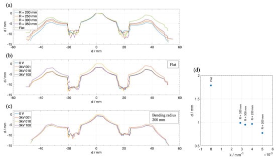
Figure 7.
(a) Comparison of the cross-sectional shape of the unactuated array in differently deformed configurations, ranging from flat to a bent configuration with a minimum radius of 200 mm. (b) Cross-sectional shapes of the flat array for different voltage configurations (0 V and 3 kV applied separately to each electrode). (c) Cross-sectional shapes of the bent array with a radius of 200 mm for different voltage configurations (0 V and 3 kV applied separately to each electrode). (d) Maximum displacement of the center DEA over the curvature of the array (1/R).

Table 2.
Results of Figure 7d.
3.3. Rigid DEA Array Characterization
3.3.1. Quasi-Static Characterization
The rigid array was characterized similarly to the flexible one. However, since the thermoformed bias make its structure not flexible, no measurement was performed in the bent state. Instead, a new experiment was performed to further demonstrate the cooperation between the single actuator elements, in which the capacitance of unactuated elements is measured while neighboring elements are actuated.
Figure 8a shows the quasi-static displacement of each single actuator element. A sinusoidal voltage signal with an amplitude of 2600 V (due to the thinner silicone membrane used for version 2) with a frequency of 0.1 Hz was applied to each element separately. Compared to the flexible array, each element shows a higher displacement, ranging from 2.2 mm to 2.8 mm. The larger stroke can be explained by the better fitting NBS curve, which is shown in Figure 4c which was achieved by the more manageable manufacturing process for the beams, the implemented tuning options and the lower resulting hysteresis compared to a silicone-based NBS. Figure 8b shows the stroke response of DEA3, when the frequency of the sinusoidal excitation signal is changed, but the amplitude is kept constant at 2600 V. With increasing frequencies, the stroke of the excited DEA element is slightly decreasing. The effect is significantly less in comparison to the previous array version. When the frequency equals 7 Hz, even a slightly larger stroke amplitude than the quasi-static one is achieved. However, this does not occur concurrently with the maximum voltage amplitude. This effect can be explained by the inertia of the accelerated mass, which accounts for the middle spring clamp, the M2 screw, and the 3D-printed plunger, which is attached to it. The resulting inertia is thus an order of higher magnitude compared to the one of the flexible array, where the accelerated mass is only due to the silicone dome and the 3D-printed connection pieces between the dome and the DE membrane. Figure 8c shows the coupling effects between the DEA elements by displaying the stroke of DEA1 when DEA3 is actuated at different frequencies (here: 0.1 Hz, 4 Hz, and 7 Hz). While in the quasi-static case the shape of the first curve is qualitatively similar to the second curve, at higher frequencies, oscillation phenomena appear in the coupled element. The amplitudes reached at 4 Hz and 7 Hz are of the same order of magnitude as in the quasi-static case; however, they are not reached simultaneously with the voltage amplitude, but with a delay. When looking at the stroke behavior over time, an oscillation in DEA1 is triggered at approximately 21 Hz. All measured stroke values for all quasi-static excitation cases are listed in Table 3.
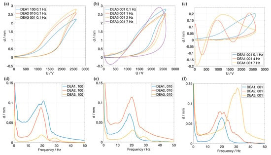
Figure 8.
(a) Comparison of the maximum quasi-static stroke of each DEA, when a voltage of 2.6 kV with a sinusoidal frequency of 0.1 Hz is applied. (b) Stroke response of DEA3 on four different excitation frequencies (0.1 Hz, 1 Hz, 4 Hz, 7 z). (c) Stroke response of DEA1, when DEA3 is excited by three different excitation signals (0.1 Hz, 4 Hz, 7 Hz). (d) FFT of the stroke response divided by the FFT of squared voltage signal of all three DEAs, when only DEA1 is excited with a sinusoidal sweep signal. (e) Same as (d), but only DEA2 is excited. (f) Same as (d), but only DEA3 is excited.

Table 3.
Quasi-static displacements of the individual actuators of the rigid array.
3.3.2. Frequency Sweep Characterization
Figure 8d–f show the coupling effects among all DEA elements in dependency of the excitation frequency, in the range between 0 Hz and 50 Hz. The figures show that the resonance frequencies of DEA1 and DEA2 lie at approximately 21 Hz and 20 Hz, while the stroke of DEA3 is maximized at about 32 Hz. Similarly to the first array version, the respective resonance frequencies are also excited when another DEA element is electrically excited, even if it does not show any resonance at this frequency. For instance, even though DEA3 shows no resonance at 21 Hz, DEA1 oscillates with a higher amplitude than DEA3, when DEA3 is excited at that frequency. Thus, regarding the cooperative aspect of the array under investigation, certain DEAs can be activated by the electrical actuation of neighboring elements without exciting large oscillations in the activated elements themselves, which is one of the major findings of this investigation.
3.3.3. Self-Sensing Characterization
As already investigated in [34,48], the capacitance of a DEA is correlated to the stroke. Therefore, it represents a key variable to monitor in the presented actuator arrays, in order to be able to leverage on self-sensing capabilities and cooperation effects. The possibilities of using self-sensing combined with the array-related coupling effects are demonstrated in a further experiment. Here, the capacitance C and the stroke d of DEA1 are measured with the LCR meter, while DEA2 is actuated by a sinusoidal voltage signal with an amplitude of 2.6 kV and a frequency of 0.1 Hz. In the following measurement, DEA2 is working against a constant load that practically limits its stroke to 0 mm. A schematic visualization of the investigated cases is shown in Figure 9c. Figure 9a shows the resulting stroke of DEA1 while DEA2 is subjected to a sinusoidal voltage of 2.6 kV, with DEA2 free to move in the first case (blue) and blocked as described above in the second (red). It is clearly shown that the stroke of DEA1 changes from around 0.9 mm to around 0.25 mm when DEA2 is blocked. Figure 9b shows the normalized capacitance signal over the laser-measured stroke of DEA1 for the same experiment. Thus, the capacitance is increased by 0.36% when DEA2 is free, and decreased by 1.2% when DEA2 is blocked, even though DEA1 is showing a positive stroke in both cases. The decrease in the capacitance of DEA1 could be explained by a reduction in its electrode surface area: the voltage applied to DEA2 leads to a reduction in the membrane thickness, and thus a simultaneous increase in the electrode area. Due to the blocking of DEA2, this increase in surface area does not lead to a stroke, but to a decrease in the overall membrane stress and, in turn, to a reduction in the electrode surface area of DEA1. The geometrical effect on the capacitance of DEA1 due to that stress reduction is bigger than the increasing effect due to the resulting stroke. This experiment shows how cooperative effects rely on the shared membrane approach. In future prototypes, this effect can be used to detect error states in the array, where one element might be blocked or malfunction.
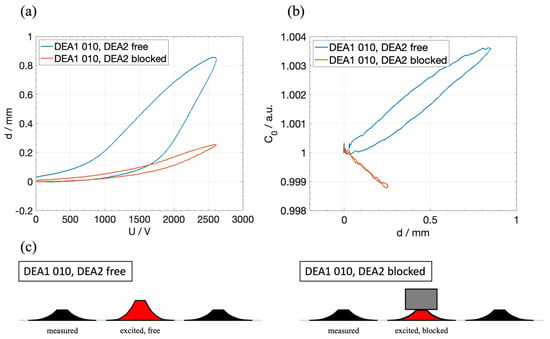
Figure 9.
(a) Resulting stroke of DEA1 when a sinusoidal voltage with an amplitude of 2.6 kV is applied to DEA2, with DEA2 free to move (blue) and blocked by a weight (red). (b) Normalized capacitance in dependency of the stroke during the same experiment. (c) Visualization of the two investigated cases, where DEA2 is free and blocked.
4. Conclusions
This work presented two novel designs of cooperative dielectric elastomer actuator arrays, each one optimized for different application scenarios. The goal was to investigate electromechanical coupling effects and evaluate the potential of integrated sensing and actuation in smart decentralized systems without the need for external sensors.
The first array version was designed as a fully flexible and soft actuator system using a silicone membrane and silicone-based domes. The latter are used as negative-stiffness biasing elements, ensuring large-stroke actuation. The fully polymeric and flexible design makes it especially suitable for wearable and close-to-body applications. The individual actuators exhibited a quasi-static stroke of up to 1.9 mm, and the array remained functional even when operated under large bending deformations, maintaining a significant 44% of its stroke at a bending radius of 200 mm. Mechanical coupling effects between actuators was also demonstrated, showing complex frequency-dependent behavior and enabling cooperative actuation, which holds great promise for future fault-tolerant designs. For example, it has been demonstrated that unactuated actuator elements can be excited to significant strokes at certain frequencies, while the actuated elements exhibit lower strokes at those frequencies.
The second version of the array was developed as a more robust hardware platform, enabling precise adjustment and replacement of each actuator element. It features thermoformed polymer-based buckling beams with optimized force–displacement characteristics, operating similarly to the silicone domes of the previous prototype but with reduced hysteresis, enhanced options for post-adjustment fine-tuning, improved long-term stability, and higher reproducibility in manufacturing. The actuators achieved a maximum stroke of up to 2.8 mm, and mechanical resonance effects were observed at approximately 20–32 Hz, depending on the actuator. Cooperative effects were further demonstrated by observing changes in stroke and capacitance of neighboring elements, even when only one actuator was actively driven. It can be seen that these effects can help to detect error states or faulty actuator elements. These self-sensing capabilities offer a new path toward real-time system monitoring and decentralized control.
In summary, this study demonstrates the feasibility and benefits of smart, polymer-based DEA arrays in cooperative systems. The ability to combine actuation and sensing in a compact, compliant structure provides a versatile platform for applications in soft robotics, wearable haptics, and adaptive systems. Future research will focus on the development of distributed control algorithms, scaling to arrays with a large number of elements or a smaller overall size, and the integration of machine learning techniques for autonomous behavior and fault diagnosis in real-world applications.
Author Contributions
Conceptualization, J.N. and A.S.; methodology, J.N., G.R. and S.S.; validation, J.N. and S.C.; formal analysis, J.N., S.C. and G.R.; investigation, J.N. and A.S.; resources, G.R. and S.S.; data curation, J.N. and A.S.; writing—original draft preparation, J.N.; writing—review and editing, G.R.; visualization, J.N.; supervision, G.R. and S.S.; project administration, G.R. and S.S.; funding acquisition, G.R. and S.S. All authors have read and agreed to the published version of the manuscript.
Funding
Funded by the Deutsche Forschungsgemeinschaft (DFG, German Research Foundation) under grant no. 424608471.
Data Availability Statement
Raw data can be provided by the corresponding author on request.
Conflicts of Interest
The authors declare no conflicts of interest.
Abbreviations
The following abbreviations are used in this manuscript.
| DE | Dielectric elastomer |
| DEA | Dielectric elastomer actuator |
| NBS | Non-linear biasing spring |
| RTV | Room-temperature-vulcanizing |
| FDM | Fused deposition modeling |
| SLA | Stereolithography |
| CAD | Computer-aided design |
| PCB | Printed circuit board |
| FFT | Fast Fourier transform |
Appendix A
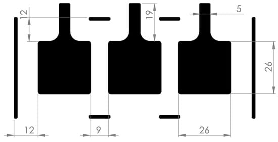
Figure A1.
Electrode dimensions of the soft DE-array.
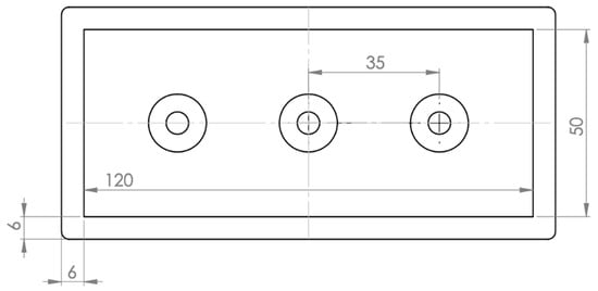
Figure A2.
Dimensions of the soft array of silicone-based biasing domes for the soft DE-array.
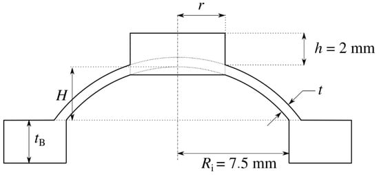
Figure A3.
Schematic of the cross-sectional view of the used dome design for the soft DE-array.

Table A1.
Table of the dimensions of the manufactured silicone-based domes for the soft DE-array.
Table A1.
Table of the dimensions of the manufactured silicone-based domes for the soft DE-array.
| Dome 1 | Dome 2 | Dome 3 | |
|---|---|---|---|
| H | 5 mm | 5 mm | 5 mm |
| r | 3 mm | 2.7 mm | 3 mm |
| t | 0.8 mm | 0.8 mm | 0.8 mm |
| tB | 5 mm | 5 mm | 5 mm |
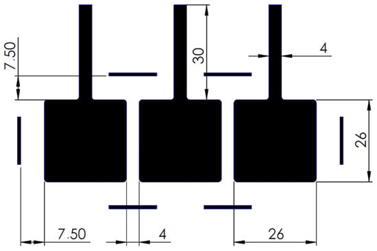
Figure A4.
Electrode dimensions of the rigid DE-array.
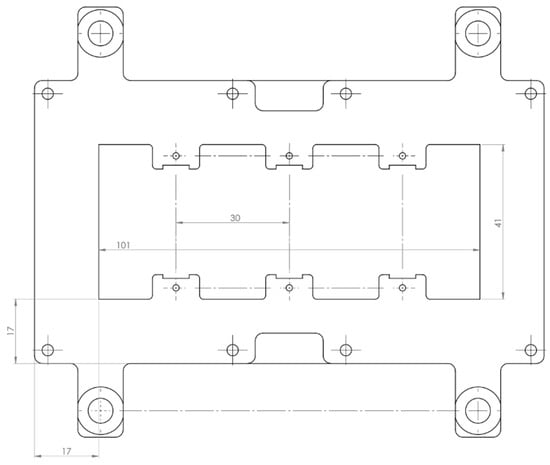
Figure A5.
Dimensions of the base plate used for the rigid DE-array.
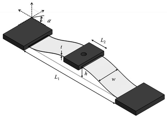
Figure A6.
CAD design of a PEEK-based thermoformed beam which was used for the rigid DE-array, displaying the characterizing geometric parameters.

Table A2.
Table of the dimensions of the manufactured thermoformed beams for the rigid DE-array.
Table A2.
Table of the dimensions of the manufactured thermoformed beams for the rigid DE-array.
| Beam 1 | Beam 2 | Beam 3 | |
|---|---|---|---|
| t | 0.1 mm | 0.1 mm | 0.1 mm |
| h | 4 mm | 4 mm | 4 mm |
| w | 7.5 mm | 7.5 mm | 7.5 mm |
| L1 | 25 mm | 25 mm | 25 mm |
| L2 | 10 mm | 10 mm | 10 mm |
| α | 27° | 28° | 28° |
References
- Gao, J.; Xiao, Y.; Liu, J.; Liang, W.; Chen, C.L.P. A Survey of Communication/Networking in Smart Grids. Future Gener. Comput. Syst. 2012, 28, 391–404. [Google Scholar] [CrossRef]
- Chen, F.; Ren, W. On the Control of Multi-Agent Systems: A Survey. Found. Trends® Syst. Control. 2019, 6, 339–499. [Google Scholar] [CrossRef]
- Vaccaro, A.; Velotto, G.; Zobaa, A.F. A Decentralized and Cooperative Architecture for Optimal Voltage Regulation in Smart Grids. IEEE Trans. Ind. Electron. 2011, 58, 4593–4602. [Google Scholar] [CrossRef]
- Patwari, N.; Ash, J.N.; Kyperountas, S.; Hero, A.O.; Moses, R.L.; Correal, N.S. Locating the Nodes: Cooperative Localization in Wireless Sensor Networks. IEEE Signal Process Mag. 2005, 22, 54–69. [Google Scholar] [CrossRef]
- Zhang, S.; Cao, Y. Cooperative Localization Approach for Multi-Robot Systems Based on State Estimation Error Compensation. Sensors 2019, 19, 3842. [Google Scholar] [CrossRef]
- Lee, J.; Park, B. Development and Evaluation of a Cooperative Vehicle Intersection Control Algorithm under the Connected Vehicles Environment. IEEE Trans. Intell. Transp. Syst. 2012, 13, 81–90. [Google Scholar] [CrossRef]
- Chandler, P.R.; Pachter, M.; Swaroop, D.; Fowler, J.M.; Howlett, J.K.; Rasmussen, S.; Schumacher, C.; Nygard, K. Complexity in UAV Cooperative Control. Proc. Am. Control. Conf. 2002, 3, 1831–1836. [Google Scholar] [CrossRef]
- Laurent, G.J.; Delettre, A.; Zeggari, R.; Yahiaoui, R.; Manceau, J.F.; Fort-Piat, N.L. Micropositioning and Fast Transport Using a Contactless Micro-Conveyor. Micromachines 2014, 5, 66–80. [Google Scholar] [CrossRef]
- Ataka, M.; Legrand, B.; Buchaillot, L.; Collard, D.; Fujita, H. Design, Fabrication, and Operation of Two-Dimensional Conveyance System with Ciliary Actuator Arrays. IEEE/ASME Trans. Mechatron. 2009, 14, 119–125. [Google Scholar] [CrossRef]
- Konishi, S.; Mita, Y.; Fujita, H. Two-Dimensional Conveyance System Using Cooperative Motions of Many Fluidic Microactuators. Adv. Robot. 2012, 12, 155–165. [Google Scholar] [CrossRef]
- Petit, L.; Hassine, A.; Terrien, J.; Lamarque, F.; Prelle, C. Development of a Control Module for a Digital Electromagnetic Actuators Array. IEEE Trans. Ind. Electron. 2014, 61, 4788–4796. [Google Scholar] [CrossRef]
- Zhao, J.; Niu, J.; Liu, L.; Yu, J. A Soft Creeping Robot Actuated by Dielectric Elastomer. In Proceedings of the Electroactive Polymer Actuators and Devices (EAPAD), San Diego, CA, USA, 8 March 2014; Volume 9056, pp. 40–45. [Google Scholar] [CrossRef]
- Tellers, M.C.; Pulskamp, J.S.; Bedair, S.S.; Rudy, R.Q.; Kierzewski, I.M.; Polcawich, R.G.; Bergbreiter, S.E. Piezoelectric Actuator Array for Motion-Enabled Reconfigurable RF Circuits. In Proceedings of the 2015 Transducers–2015 18th International Conference on Solid-State Sensors, Actuators and Microsystems (TRANSDUCERS), Anchorage, AK, USA, 21–25 June 2015; Institute of Electrical and Electronics Engineers Inc.: New York, NY, USA, 2015. [Google Scholar]
- Vandelli, N.; Wroblewski, D.; Velonis, M.; Bifano, T. Development of a MEMS Microvalve Array for Fluid Flow Control. J. Microelectromechanical Syst. 1998, 7, 395–402. [Google Scholar] [CrossRef]
- Loverich, J.J.; Kanno, I.; Kotera, H. Concepts for a New Class of All-Polymer Micropumps. Lab. Chip 2006, 6, 1147–1154. [Google Scholar] [CrossRef]
- Hill, M.; Rizzello, G.; Seelecke, S. Development and Experimental Characterization of a Pneumatic Valve Actuated by a Dielectric Elastomer Membrane. Smart Mater. Struct. 2017, 26, 085023. [Google Scholar] [CrossRef]
- Pei, Q.; Rosenthal, M.; Stanford, S.; Prahlad, H.; Pelrine, R. Multiple-Degrees-of-Freedom Electroelastomer Roll Actuators. Smart Mater. Struct. 2004, 13, N86–N92. [Google Scholar] [CrossRef]
- Jung, K.; Koo, J.C.; Nam, J.D.; Lee, Y.K.; Choi, H.R. Artificial Annelid Robot Driven by Soft Actuators. Bioinspir Biomim. 2007, 2, S42. [Google Scholar] [CrossRef]
- Shian, S.; Bertoldi, K.; Clarke, D.R. Use of Aligned Fibers to Enhance the Performance of Dielectric Elastomer Inchworm Robots. In Proceedings of the Proceedings Volume 9430, Electroactive Polymer Actuators and Devices (EAPAD), San Diego, CA, USA, 1 April 2015; Volume 9430, pp. 417–425. [Google Scholar] [CrossRef]
- Kofod, G.; Wirges, W.; Paajanen, M.; Bauer, S. Energy Minimization for Self-Organized Structure Formation and Actuation. Appl. Phys. Lett. 2007, 90, 081916. [Google Scholar] [CrossRef]
- Hu, T.; Lu, X.; Liu, J. Inchworm-Like Soft Robot with Multimodal Locomotion Using an Acrylic Stick-Constrained Dielectric Elastomer Actuator. Adv. Intell. Syst. 2023, 5, 2200209. [Google Scholar] [CrossRef]
- Huang, B.; Li, M.; Mei, T.; McCoul, D.; Qin, S.; Zhao, Z.; Zhao, J. Wearable Stretch Sensors for Motion Measurement of the Wrist Joint Based on Dielectric Elastomers. Sensors 2017, 17, 2708. [Google Scholar] [CrossRef]
- Kelley, C.R.; Kauffman, J.L. Towards Wearable Tremor Suppression Using Dielectric Elastomer Stack Actuators. Smart Mater. Struct. 2020, 30, 025006. [Google Scholar] [CrossRef]
- Qu, X.; Ma, X.; Shi, B.; Li, H.; Zheng, L.; Wang, C.; Liu, Z.; Fan, Y.; Chen, X.; Li, Z.; et al. Refreshable Braille Display System Based on Triboelectric Nanogenerator and Dielectric Elastomer. Adv. Funct. Mater. 2021, 31, 2006612. [Google Scholar] [CrossRef]
- Frediani, G.; Busfield, J.; Carpi, F. Enabling Portable Multiple-Line Refreshable Braille Displays with Electroactive Elastomers. Med. Eng. Phys. 2018, 60, 86–93. [Google Scholar] [CrossRef]
- Solano-Arana, S.; Klug, F.; Mößinger, H.; Förster-Zügel, F.; Schlaak, H.F. A Novel Application of Dielectric Stack Actuators: A Pumping Micromixer. Smart Mater. Struct. 2018, 27, 074008. [Google Scholar] [CrossRef]
- Schlatter, S.; Grasso, G.; Rosset, S.; Shea, H. Inkjet Printing of Complex Soft Machines with Densely Integrated Electrostatic Actuators. Adv. Intell. Syst. 2020, 2, 2000136. [Google Scholar] [CrossRef]
- Wang, L.; Hayakawa, T.; Ishikawa, M.; Zhang, Y.D.; Lien, V.; Berdichevsky, Y.; Choi, J.; Lo, Y.-H. Dielectric-Elastomer-Based Fabrication Method for Varifocal Microlens Array. Optics Express 2017, 25, 31708–31717. [Google Scholar] [CrossRef]
- Akbari, S.; Shea, H.R. Microfabrication and Characterization of an Array of Dielectric Elastomer Actuators Generating Uniaxial Strain to Stretch Individual Cells. J. Micromechanics Microengineering 2012, 22, 045020. [Google Scholar] [CrossRef]
- Akbari, S.; Shea, H.R. An Array of 100 Μm × 100 Μm Dielectric Elastomer Actuators with 80% Strain for Tissue Engineering Applications. Sens. Actuators A Phys. 2012, 186, 236–241. [Google Scholar] [CrossRef]
- Ji, X.; Liu, X.; Cacucciolo, V.; Civet, Y.; El Haitami, A.; Cantin, S.; Perriard, Y.; Shea, H. Untethered Feel-Through Haptics Using 18-Μm Thick Dielectric Elastomer Actuators. Adv. Funct. Mater. 2021, 31, 2006639. [Google Scholar] [CrossRef]
- Lee, H.S.; Phung, H.; Lee, D.H.; Kim, U.K.; Nguyen, C.T.; Moon, H.; Koo, J.C.; Nam, J.D.; Choi, H.R. Design Analysis and Fabrication of Arrayed Tactile Display Based on Dielectric Elastomer Actuator. Sens. Actuators A Phys. 2014, 205, 191–198. [Google Scholar] [CrossRef]
- Croce, S.; Neu, J.; Hubertus, J.; Schultes, G.; Seelecke, S.S.; Fasolt, B.; Rizzello, G. Self-Sensing Investigation of a Dielectric Elastomer Actuator Array. In Proceedings of the Electroactive Polymer Actuators and Devices (EAPAD) XXVI, Long Beach, CA, USA, 9 May 2024; Volume 12945, pp. 58–69. [Google Scholar] [CrossRef]
- Croce, S.; Neu, J.; Moretti, G.; Hubertus, J.; Schultes, G.; Rizzello, G. Finite Element Modeling and Validation of a Soft Array of Spatially Coupled Dielectric Elastomer Transducers. Smart Mater. Struct. 2022, 31, 084001. [Google Scholar] [CrossRef]
- Michel, S.; Zhang, X.Q.; Wissler, M.; Löwe, C.; Kovacs, G. A Comparison between Silicone and Acrylic Elastomers as Dielectric Materials in Electroactive Polymer Actuators. Polym. Int. 2009, 59, 391–399. [Google Scholar] [CrossRef]
- Huang, J.C. Carbon Black Filled Conducting Polymers and Polymer Blends. Adv. Polym. Technol. 2002, 21, 299–313. [Google Scholar] [CrossRef]
- Benslimane, M.; Gravesen, P.; Sommer-Larsen, P. Mechanical Properties of Dielectric Elastomer Actuators with Smart Metallic Compliant Electrodes. In Proceedings of the Smart Structures and Materials 2002: Electroactive Polymer Actuators and Devices (EAPAD), San Diego, CA, USA, 11 July 2002; Volume 4695, pp. 150–157. [Google Scholar] [CrossRef]
- Lotz, P.; Matysek, M.; Schlaak, H.F. Fabrication and Application of Miniaturized Dielectric Elastomer Stack Actuators. IEEE/ASME Trans. Mechatronics 2011, 16, 58–66. [Google Scholar] [CrossRef]
- Cao, C.; Conn, A.T. Performance Optimization of a Conical Dielectric Elastomer Actuator. Actuators 2018, 7, 32. [Google Scholar] [CrossRef]
- He, T.; Cui, L.; Chen, C.; Suo, Z. Nonlinear Deformation Analysis of a Dielectric Elastomer Membrane–Spring System. Smart Mater. Struct. 2010, 19, 085017. [Google Scholar] [CrossRef]
- Keplinger, C.; Li, T.; Baumgartner, R.; Suo, Z.; Bauer, S. Harnessing Snap-through Instability in Soft Dielectrics to Achieve Giant Voltage-Triggered Deformation. Soft Matter 2012, 8, 285–288. [Google Scholar] [CrossRef]
- Follador, M.; Cianchetti, M.; Mazzolai, B. Design of a Compact Bistable Mechanism Based on Dielectric Elastomer Actuators. Meccanica 2015, 50, 2741–2749. [Google Scholar] [CrossRef]
- Loew, P.; Rizzello, G.; Seelecke, S. A Novel Biasing Mechanism for Circular Out-of-Plane Dielectric Actuators Based on Permanent Magnets. Mechatronics 2018, 56, 48–57. [Google Scholar] [CrossRef]
- Neu, J.; Hubertus, J.; Croce, S.; Schultes, G.; Seelecke, S.; Rizzello, G. Fully Polymeric Domes as High-Stroke Biasing System for Soft Dielectric Elastomer Actuators. Front. Robot. AI 2021, 8, 171. [Google Scholar] [CrossRef]
- Addario, S.; Priuli, A.; Hubertus, J.; Gratz-Kelly, S.; Neu, J.; Schultes, G.; Seelecke, S.S.; Rizzello, G. Thermoplastic-Polymer-Based Negative Stiffness Biasing Mechanism for High Stroke Dielectric Elastomer Actuator Systems. In Proceedings of the Electroactive Polymer Actuators and Devices (EAPAD) XXVI, Long Beach, CA, USA, 9 May 2024; Volume 12945, pp. 79–90. [Google Scholar] [CrossRef]
- Qiu, J.; Lang, J.H.; Slocum, A.H. A Curved-Beam Bistable Mechanism. J. Microelectromechanical Syst. 2004, 13, 137–146. [Google Scholar] [CrossRef]
- Croce, S.; Neu, J.; Hubertus, J.; Seelecke, S.; Schultes, G.; Rizzello, G. Model-Based Design Optimization of Soft Polymeric Domes Used as Nonlinear Biasing Systems for Dielectric Elastomer Actuators. Actuators 2021, 10, 209. [Google Scholar] [CrossRef]
- Neu, J.; Croce, S.; Willian, T.; Hubertus, J.; Schultes, G.; Seelecke, S.; Rizzello, G. Distributed Electro-Mechanical Coupling Effects in a Dielectric Elastomer Membrane Array. Exp. Mech. 2023, 63, 79–95. [Google Scholar] [CrossRef]
Disclaimer/Publisher’s Note: The statements, opinions and data contained in all publications are solely those of the individual author(s) and contributor(s) and not of MDPI and/or the editor(s). MDPI and/or the editor(s) disclaim responsibility for any injury to people or property resulting from any ideas, methods, instructions or products referred to in the content. |
© 2025 by the authors. Licensee MDPI, Basel, Switzerland. This article is an open access article distributed under the terms and conditions of the Creative Commons Attribution (CC BY) license (https://creativecommons.org/licenses/by/4.0/).