Abstract
End-effectors are becoming increasingly vital in orbital space missions, performing increasingly complex operational tasks. Current on-orbit missions primarily utilize net systems and rigid grippers as manipulators. However, the dynamic analysis of the net system is complicated, and its reliability is insufficient. Moreover, rigid grippers are not impact-resistant, which can lead to the target either rebounding or sustaining damage. This paper designs an adaptive gripper for rapid passive grasping. Adjusting the initial setup of the gripper by altering the cables allows for different degrees of trigger sensitivity to be achieved. The gripper presented in this paper integrates a bistable mechanism with a dual-mode actuation system, achieving performance metrics such as a activation time and a capture speed. This combination of rapid passive and controllable active grasping demonstrates a novel and effective solution with significant potential for dynamic on-orbit service and debris removal missions.
1. Introduction
End-effectors are becoming increasingly vital in orbital space missions, undertaking increasingly complex operational tasks. In space on-orbit operation and capturing missions, the commonly used manipulators mainly include net systems and rigid grippers. The net system in on-orbit space missions functions primarily for capturing and removing space debris. It assists in the secure capture and stabilization of target objects and enables flexible docking and towing operations [1]. Net systems are able to adapt to irregular shapes and sizes [2]. They also offer benefits of simplicity, light weight, cost-effectiveness, and reduced collision damage [3]. However, these systems are limited by poor accuracy and low target tolerance. In addition, affected by factors such as microgravity and radiation in the space environment, the net system may gradually degrade or become brittle, which is not as reliable as rigid grippers [4,5]. The rigid gripper achieves precise capture through intricate design and control algorithms [6], but its stiffness demands complex controls [7,8], risking damage to objects. Meanwhile, manipulators must respond quickly to capture fast-moving targets in space missions.
To address slow manipulator response, insufficient vibration absorption, and reliance on extra sensors for target detection, some studies propose a bistable mechanism for passive-triggered grasping solutions. Zou et al. [9] designed a soft gripper, inspired by the Venus flytrap’s stress-response, capable of high-speed grasping. Liu et al. [10] developed a cable-driven bistable gripper using an origami design, capable of fast response and cable-assisted recovery post-grasping. Dong et al. [11] designed a gripper with a bistable mechanism to achieve agile grasping of flexible and rigid objects of various shapes. However, in the harsh conditions of space, soft materials tend to degrade or fail, compromising their long-term stability and limiting their grasping capacity. Jiang et al. [12] explored reducing trigger force to enhance bistable gripper speed. Stewart et al. [13] designed a gripper with a bistable mechanism. It is used to mount on a UAV and mimics the claws of birds, which can assist the UAV in achieving stable perching. However, this gripper can only grasp cylindrical objects.
Accurate force sensing is crucial for effective grasping force control. The sensorless force sensing method models the relationship between grasping force and gripper deformation. This approach is a prominent area of current research [14]. The main approaches to modeling grasping force and deformation mapping are data-driven methods, kinetics modeling, and data-driven methods, often incorporating neural networks. Data-driven methods learn complex relationships without physical models. Mao et al. [15] used a data-driven approach to establish the mapping relationship between the signal of the FBG and the force applied to an adaptive Fin-Ray finger. This allowed them to analyze the force applied to the finger. Cui et al. [16] developed a learning-based method for sliding detection to enhance robotic grasping success. However, this method lacks generalization and is prone to overfitting. It lacks an interpretable physical basis, robustness, and resistance to external perturbations. The comprehensive kinetics modeling method provides excellent interpretability, broad applicability, and consistency. Gao et al. [17] modeled a cable-driven continuum robot for shape and tip force sensing. Chen et al. [18] modeled adaptive Fin-Ray fingers to sense the shape of grasped objects. However, this method is computationally costly and challenging to solve with complex nonlinear equations. Data-driven methods can be combined with static models, where a neural network learns to compensate for the model’s inaccuracies by fitting the residual error, thereby improving overall prediction accuracy. This method requires less experimental data and offers physical interpretability and generalization, merging the benefits of both data-driven and full physical modeling approaches.
To address the above challenges, we propose an adaptive gripper with a rigid link-hinge structure in this paper. The gripper integrates the robust grasping capability of a rigid gripper with the adaptability associated with an adaptive gripper. Constructed from entirely metallic materials, it is engineered to ensure the prolonged and stable operation of the gripper under extreme thermal conditions and intense electromagnetic fields. The gripper employs a bistable mechanism that uses snap-through characteristics for passive, adjustable sensitivity grasping. This reduces the necessity for precise control, thereby increasing the success rate of capturing moving targets. Furthermore, this passive trigger grasping is realized without dependence on a motor drive. The passive grasping capability allows the gripper to function effectively during power loss or in low-power mode. The bistable mechanism provides impact resistance, reducing the target’s impact on the robot arm when captured. Integrating a motor at the remote end with a cable enables active grasping and tension reset as needed. The mass and size of the motor neither puts an additional burden on the robot arm nor affect the size and mass of the gripper. The gripper proposed in this paper not only has fast response characteristics but is also equipped with sensorless grasping force sensing capability. This feature further improves its grasping adaptability and reliability. The main contributions of this paper are summarized as follows: We present the design and implementation of a novel dual-mode adaptive gripper that integrates a rigid-link bistable mechanism for rapid passive capture with a cable-driven system for controllable active grasping. We conduct a comprehensive experimental validation of a physical prototype, demonstrating key performance metrics and verifying its capabilities in both passive, active, and collaborative grasping scenarios. This serves as a concept validation for its application in on-orbit tasks. We propose and validate a sensorless force estimation method that combines a static analytical model with a data-driven error compensation network, achieving accurate force sensing without dedicated force sensors.
The sections of this paper are arranged as follows: Section 2 describes the gripper’s construction as presented in this paper. It details the layout of the passive triggered bistable mechanism and the finger configuration. Section 3 provides a detailed explanation of the sensorless force sensing method. Section 4 presents the gripper’s experimental validation, emphasizing passive triggering sensitivity, force sensing, and multimodal grasping. Section 5 clarifies and interprets several important aspects of this work. Section 6 summarizes the paper.
2. Structural Design
This section details the adaptive gripper’s structure, focusing on its grasping flexibility and fast responsiveness. Grippers face higher demands in scenarios like grasping fast-moving objects (speed ), sorting on production lines, and capturing space debris. These scenarios require a rapid grasping capability. In order to achieve an accurate and fast grasp of high-speed moving objects, the gripper needs to have high-speed dynamic response grasping ability. Additionally, it must effectively buffer and quickly grasp the target. The gripper can adapt to and grasp objects of various shapes.
2.1. Main Structure of the Gripper
The main structure of the gripper is shown in Figure 1a and consists of fingers as well as the actuation mechanism. Three adaptive fingers are evenly spaced apart. The actuation mechanism facilitates the opening and closing operations of the gripper by actuating the fingers. The gripper discussed in this paper utilizes the rocker slider mechanism depicted in Figure 1d to achieve its operational movement. The prime mover slider executes a reciprocating motion, thereby actuating the rocker about the hinge. Fingers rotate with the rocker to open and close the gripper.
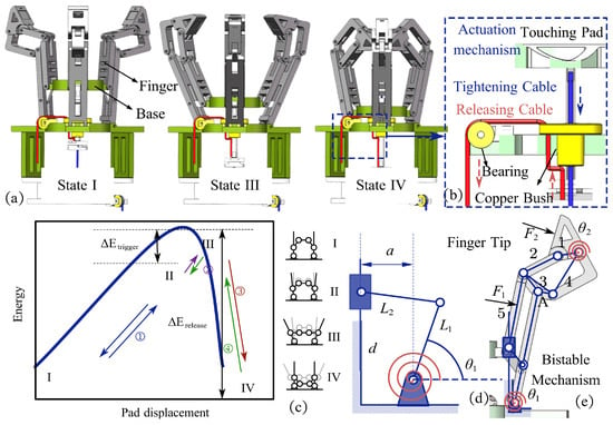
Figure 1.
Scheme of the structure of the gripper. (a) Two stable states (State I and IV) and maximum energy state of the gripper (State III). (b) Actuation mechanism of the gripper. (c) Energy-displacement curve of the bistable mechanism. (d) Rocker slider mechanism. (e) Scheme of the structure of the finger.
To quickly grasp fast-moving targets, the gripper’s actuation mechanism must swiftly move and buffer the target efficiently. We design a bistable actuation mechanism utilizing snap-through characteristics to achieve a fast response. In Figure 1d, a torsion spring serves as an energy storage element at the slider-rocker mechanism’s hinge. It stores energy when deformed and returns to its original shape upon release.
Besides being able to quickly perform passive triggered grasping when mechanically stimulated, the gripper should also possess the capability for active grasping and should be able to reset after grasping. In this study, we attach two cables to the trigger plate, which apply tension to facilitate active grasping by the gripper. This setup also enables the opening and resetting of the gripper following its grasping action. In Figure 1b, the blue arrow illustrates the downward tension on the trigger plate caused by one of the cables acting as the tightening cable, facilitating the gripper’s active grasping capability. Meanwhile, the red arrow indicates that the releasing cable, routed through a specially designed guided bearing pulley, applies upward tension on the trigger plate. The counteracting tension from the two opposing cables counterbalances the abrupt leaps and movements of the bistable mechanism, enabling the trigger plate to perform a controlled back-and-forth motion under the influence of an external actuation force. Simultaneously actuating both cables adjusts the trigger plate’s position prior to passive grasping, thereby allowing for the fine-tuning of the gripper’s passive trigger sensitivity.
The two cables are driven using two separate motors. Different from traditional grippers wherein the motor is incorporated within the internal structure of the gripper, this study presents a gripper with a segregated motor configuration. In this arrangement, the gripper is affixed at the end of the arm, while the motor can be situated at the base of the arm. A cable extends from the motor and traverses the alignment pipe along the arm. It connects via micro-bearings to the trigger plate of the gripper. This connection facilitates remote operation of the gripper. The activation of the motor initiates the motion of the cable. Consequently, this motion actuates the trigger plate, thereby enabling the gripper to execute opening and closing. The motor and gripper are not rigidly connected, preventing direct impact on the motor during collisions and protecting it. This separation significantly reduces the gripper’s size and weight, minimizing the arm’s load.
2.2. Parameter Selection for the Bistable Mechanism
The primary feature of the gripper developed in this paper is that its actuation system employs the snap-through behavior of a bistable mechanism, enabling swift passive trigger grasping of the target. Optimizing the distribution of link lengths in the rocker-slider mechanism within the driving component is vital for ensuring a robust and reliable snap-through behavior. The goal of the parameter selection process is to achieve a desirable energy profile, characterized by a sufficiently high potential energy barrier () to prevent accidental triggering and a significant energy release () to ensure a rapid and complete grasping motion. This state represents the highest level of elastic potential energy. This mechanism employs a torsion spring for energy storage, and the relationship between the stored elastic potential energy E of the torsion spring and its turning angle is given by:
where k is the stiffness of the torsion spring. The angle of rotation of the torsion spring is a function of the length of the rigid links , , the eccentricity a and the displacement of the trigger plate:
where
where
Equation (1) indicates that maximum elastic potential energy occurs at the peak torsion spring angle . By defining the eccentricity a as the unit length, we express the ratios of rigid links and to the eccentricity a as the relative lengths and . This relates the peak torsion spring angle to the relative lengths and .
Simultaneously, as the mechanism shifts from peak state III to steady state IV, the proportion of the trigger plate displacement relative to the entire stroke d diminishes. Consequently, the switching process becomes more rapid:
Moreover, the biased rocker slider mechanism described in this paper is subject to geometric constraints:
Consequently, the problem of optimizing the length allocation of rigid links in the actuation mechanism is inherently a multi-objective optimization problem. The multi-objective optimization problem is converted into a single-objective optimization problem using the weighted sum method, structured as follows:
where and are the weights of the two objectives, here taken as respectively. Given the monotonic nature of the objective function in Equation (10) within the defined constraints, the optimal parameters lie on the boundary of the feasible design space. Therefore, the boundary values were selected to maximize the objective function. The results were taken as and . Considering the overall dimensions of the manipulator, the eccentricity a is taken as 4 mm, then and are taken as 25 mm and 24 mm respectively. The controlled variable method is utilized to assess the energy associated with the mechanism for varying lengths of rigid links and , as well as the eccentricity a. The findings are presented in Figure 2.
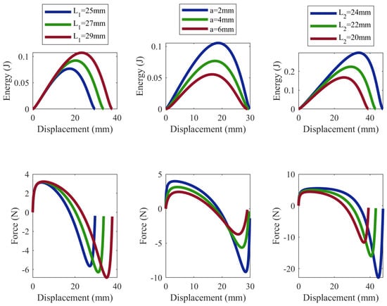
Figure 2.
Energy-displacement curve and force–displacement curve of the bistable mechanism with different parameters.
As illustrated in Figure 2, when the eccentricity a is modified alongside proportional adjustments in the lengths and , the entire stroke d of the trigger plate varies correspondingly. However, the system’s maximum elastic potential energy remains constant.
Adjusting the position of state II on the energy curve in Figure 1c is possible by pulling the two cables and modifying the trigger plate’s position. This alteration allows for the tuning of the bistable mechanism’s sensitivity regarding passive grasping activation.
2.3. Adaptive Finger Design
Achieving adaptive grasping for objects of varying shapes and sizes is a crucial capability for a gripper. For differently shaped and sized objects, the gripper adapts its configuration to ensure a stable and dependable grasp, preventing the objects from being easily dislodged. As illustrated in Figure 1a, the gripper developed in this study incorporates three identical adaptive fingers, each positioned at intervals around the gripper and connected to its trigger plate. The finger’s main structure is composed of rigid links and hinges as shown in Figure 1e, allowing for adaptive deformation under applied stress.
The fingertip of the finger features a double rocker mechanism, illustrated in Figure 1e. Within this mechanism, link 3 acts as the frame, while link 1, a triangular frame, functions as the fingertip, making contact with the grasped object. By integrating a torsion spring at the hinge where links 1 and 4 connect, the position of the fingertips is uniquely defined. This allows for a snug and adaptive grasp that conforms to the object’s shape. Simultaneously, the torsion spring serves as an energy storage buffer, minimizing potential damage to the target or the gripper itself from excessive impact or the force applied when grasping.
To enhance the gripper’s grasping space, the length and configuration of link 3 at the fingertip are optimized. Link 3 is a rigid V-shaped component, defined by the angle of the V-shaped configuration at node A. For any object shape, identifying its smallest enclosing circle helps determine its maximum occupied area. Consequently, a sphere is selected as the outer boundary shape of the object being grasped for analyzing and optimizing the gripper’s grasping space. The analysis and optimization of the gripper’s grasping space focus on the maximum horizontal grasp dimension X and the minimum vertical grasp dimension Y. Different V-clamp angles at node A are evaluated for their impact on grasping and redundancy space, with the results detailed in Table 1.

Table 1.
Grasping space with different angle configurations.
With a V-shaped angle of , the gripper maximizes its grasping space, but there is significant redundant fingertip space. At , the grasping space remains large with minimized redundancy, so the V-shape is set to .
3. Force Sensing Method
This section presents the main idea of the sensorless force sensing method designed for the proposed gripper. We apply the data-driven error compensation for force sensing. Initially, a static model is developed to map the contact force with the angle of the finger link, thus explaining how these two variables relate. Subsequently, a neural network is employed to learn and adjust the discrepancy between the contact force estimated by the static model and the actually measured force. By integrating the constraints of the static model into the loss function, the correction is more consistent with physical principles. The combination of the static model with data-driven error adjustments enhances the accuracy of force sensing. This method also mitigates overfitting, thereby boosting the generalization capability.
3.1. Static Modeling
Initially, the link angle and contact force relationship was represented using a static model. This model was developed under the following assumptions:
- The rigid links are all uniform rigid rods, and the gravity they experience can be ignored.
- Links 1 and 5 of each finger remain in contact with the object and are thus subjected to contact forces. The external forces are applied at the midpoint of the rigid links. The force applied to the trigger plate is equivalent to the sum of the forces exerted by the three fingers.
The finger consists of rigid links joined by hinges, where two of these hinges are equipped with torsion springs. As the fingers undergo deformation, the links rotate at the movable hinges, altering their angles. The torsion springs have stiffness constants of and , while the rotation angles are and accordingly. The resulting torques from spring torsion are:
According to the principle of virtual work, there are:
refers to the contact force, and indicates displacement along its direction. The contact force aligns with the normal to the rigid link. The resolution of Equation (12) enables the determination of . Image processing methods are employed to measure the rotation angles, referred to as . Measured results are then substituted into to calculate the contact force exerted by the finger.
Here, Equation (12) is presented as a scalar equation. This is a valid simplification because, due to the three-finger symmetric design of the gripper, the contact forces are assumed to be primarily normal to the contact surfaces, and we are interested in the magnitude of these forces. The principle of virtual work is employed as it provides a direct and efficient method for relating forces and displacements in a multi-body system without needing to solve for complex internal constraint forces at the joints.
3.2. Data-Driven Error Compensation
The static model described in Section 3.1 provides a valuable physical basis for force estimation but is subject to errors from model simplification, unmodeled friction, and inaccuracies in visual angle measurement. To enhance the accuracy, we employ a data-driven approach to compensate for these residual errors.
A feedforward neural network (FNN) is used as an error compensation function, denoted as . The network takes the measured joint angles as input and outputs the predicted error between the real force and the force calculated by the static model . The final, more accurate force prediction is then:
For each data point, the joint angles were measured by the camera system, while the ground-truth contact force was simultaneously recorded by the force sensors. The objective of the training is to minimize the mean squared error between the estimated force and the real force:
This hybrid approach is particularly effective. The static model provides physical interpretability, while the neural network learns to correct for complex, non-linear effects. This includes subtle phenomena such as minor misalignments in force application on the sensors, which are challenging to capture analytically. The model’s hyperparameters (e.g., number of layers and neurons) were determined through standard cross-validation to achieve the best performance on a held-out test set.
4. Experiments
This section presents experimental validation of the proposed design and sensing method. First, the gripper’s rapid response capability was confirmed. Second, the multimodal grasping in practical scenarios was verified. Lastly, the force sensing capability was validated.
4.1. Rapid Response Experiments
This section tests the rapid response of the designed gripper’s passive trigger grasping. The analysis covers four aspects: response time of the bistable mechanism, time for stable grasping, minimum trigger energy, and maximum object grasping speed. After evaluating the gripper’s performance, its ability for passive trigger grasping is confirmed by capturing fast-moving, non-cooperative objects.
To test the bistable mechanism’s response time, the gripper was set on a stable optical platform, a tennis ball was released above it, and the triggering process was filmed with a high-speed camera at a frame rate of . As illustrated in Figure 3a, the experiment was conducted 3 times, and the average of three results was considered as the response time. The gripper completes the trigger in less than and the grasp in . The fast-response gripper is designed primarily to capture targets at high speed; thus, the highest velocity at which the gripper is able to seize a target is evaluated. As shown in Figure 3b, the gripper is mounted on a horizontally stable optical platform, with its passive trigger sensitivity adjusted to the highest level. The tennis ball is released directly above the gripper, with its release height gradually raised until it can no longer be captured by the gripper. In cases where the release height exceeded , the ball’s velocity was too high () for the gripper’s fingers to fully close before impact, causing the ball to collide with the partially closed fingers and bounce away. To evaluate the minimum energy necessary to activate the bistable mechanism, the gripper is positioned on a horizontally stable optical platform. The sensitivity of the gripper is adjusted to its maximum state through the cooperation of the tightening and releasing cables. As illustrated in Figure 3c, standardized mass weights are released from varying heights, and both the mass and height parameters are systematically adjusted until the bistable mechanism is activated to induce a snap-through phenomenon. The experimental findings indicate that the minimum energy required to trigger the mechanism is approximately when the gripper’s sensitivity is optimized to its highest level. The stability of the gripper’s grasping is evaluated using standard mass weights, depicted in Figure 3d. As the weight is incrementally raised, the gripper’s pull-out force also increases. Experimental findings reveal that the gripper can endure a pull-out force equivalent to the gravitational force exerted by an 1 kg object.
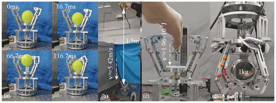
Figure 3.
Fast response experiments of the gripper. (a) Trigger time of the gripper is , and grasping time is . (b) Maximum grasping speed experiment. (c) Minimum trigger energy experiment. (d) Maximum pull-out force experiment.
4.2. Experiments of Multimodal Grasping
Based on the experiments detailed in the previous section, which examined the passive triggering grasping response speed of the designed gripper, this section further investigates the gripper’s capabilities for multimodal grasping.
First, the passively trigger grasping ability of the gripper is verified. As illustrated in Figure 4, the gripper is attached to the end of a UR5 robotic arm. When the tightening cable is pulled, the trigger plate moves downward. The torsion spring accumulates energy, shifting the system’s energy from stable state I towards, but not reaching, its peak energy level. This enhances the sensitivity of the gripper’s passive trigger. Upon tossing a tennis ball into the air, the robotic arm is guided to intercept the ball in motion. The system energy elevates as the moving tennis ball contacts the gripper, going beyond the system’s energy peak. Consequently, the gripper activates, allowing passive triggering and capture of the moving target. As shown in the figure, this bistable gripper can swiftly and reliably grasp non-cooperative flying objects within .
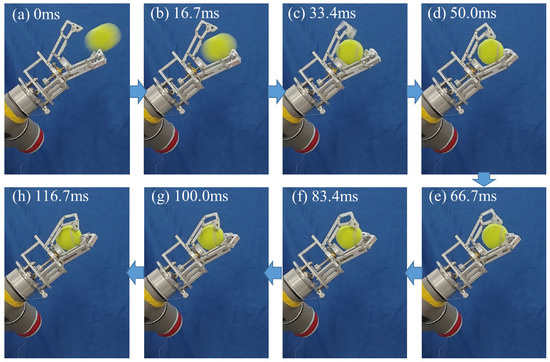
Figure 4.
Passive trigger grasping. Object can be grasped in no more than .
The gripper features both active and passive grasping modes. In situations where there is no direct contact with the target to gain energy input, the gripper’s operation of opening and closing can be achieved by pulling a cable, thus facilitating active grasping of the target. Here, the active grasping ability of the gripper is verified. Objects with various shapes were chosen as the targets for grasping. They were successfully grasped by the gripper in no more than , and the outcomes are presented in Figure 5.
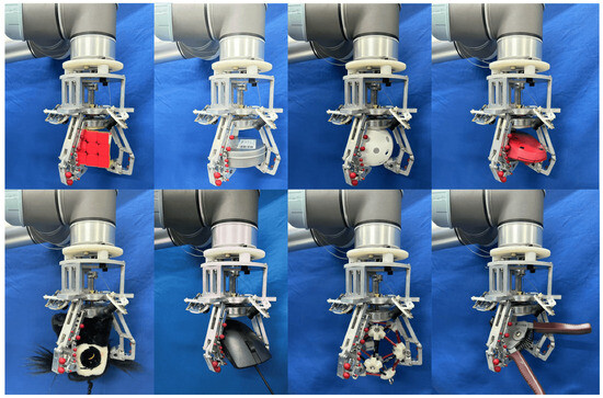
Figure 5.
Adaptive active grasping experiments. Objects with various shapes can be grasped in no more than .
The experimental results reveal that the gripper is capable of achieving both rapid passive grasping and steady active grasping. Additionally, it can facilitate the transition and collaboration between active and passive grasping modes during the grasping process via the host computer.
After verifying the gripper’s proficiency in both active and passive trigger modes for grasping, further experiments were performed to evaluate its ability for active and passive collaborative grasping. As shown in Figure 6, a tennis ball was tossed into the air, while the gripper was maneuvered to intercept the ball mid-air, operating in passive grasping mode. Upon contact with the tennis ball, the gripper engaged and cushioned the ball. Subsequently, the gripper switched to active grasping mode, where the grasping force was increased through cable tensioning to secure a more stable hold. The experimental results indicate that the cooperatively grasping bistable gripper benefits from rapid responsiveness and impact mitigation, attributed to its bistable design, along with stable positioning and secure grasping, attributed to its dual-motor system.

Figure 6.
Active and passive collaborative grasping. The arrows indicate the sequence of operation: (a) to (b): the gripper first operates in a high-sensitivity ’passive grasping’ mode to intercept the ball, then (b) to (c): switches to ’active grasping’ mode, using cable tension to secure the hold.
4.3. Force Sensing Experiments
Another important feature of the gripper designed in this paper is its ability to sense the grasping force. This part of the experiment verifies the effectiveness and sensing accuracy of the force sensing method proposed in this paper.
The arrangement designed to verify the force sensing method, illustrated in Figure 7a,b, comprises primarily the gripper under examination and a sensor holder that houses multiple force sensors. The holder, made of 3D-printed PLA, features precisely located slots where three SBT674-10 force sensors (SBT Electronic Technology Co., Ltd., Guangzhou, China) are securely embedded. To provide a clear visual guide for the camera-based angle measurement system, spherical red markers are attached to the gripper’s links. The camera captures data at a rate of , while the sensor gathers data at the same rate of . The camera’s measured rotation angle is integrated into the force sensing model introduced in Section 3 to finalize the force sensing process. The results of the force sensing are compared with the results measured by the sensor, and the results are shown in Figure 7c.
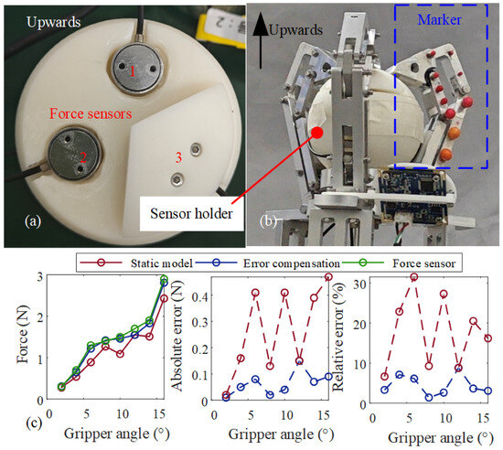
Figure 7.
Force sensing experiments. (a) Sensor holder designed for force sensors. (b) Sensor holder in the gripper for force sensing experiments. (c) Force sensing results compared with sensor measured ones.
The figure illustrates that utilizing a static model for force sensing results in a significant relative error, reaching as high as 31.92%. This error largely stems from inaccuracies in visual measurement and the approximations made regarding contact position. However, the application of a data-driven error compensation method together with the static model substantially enhances the accuracy, reducing the maximum relative error from 31.92% to 9.10%. This demonstrates the proposed force sensing method’s efficacy.
5. Discussion
In this section, we further analyze our results, contextualize our work by comparing it with the state-of-the-art grippers, and we discuss its practical applications and limitations.
5.1. Performance in Context: A Comparative Analysis
To better situate the contributions of our work, we present a quantitative comparison with several state-of-the-art space grippers in Table 2.

Table 2.
Comparisions among different grippers.
The comparison highlights that our gripper achieves a superior or highly competitive rapid-capture speed and response time, which is critical for capturing non-cooperative targets. While some specialized grippers may offer higher grasping forces, our design provides a unique balance of rapid passive response and controllable active grasping, a feature not commonly found in other systems.
5.2. Practical On-Orbit Application Scenarios
The dual-mode capability is designed for operational flexibility in space. For instance:
Debris Capture: When capturing an uncontrolled, tumbling piece of debris, the gripper would be set to a high-sensitivity passive mode. This allows for an instantaneous, energy-efficient capture upon contact, without requiring complex real-time control.
On-Orbit Servicing: When manipulating a cooperative satellite or a tool, the operator would use the active mode. This allows for precise control over the grasping force and deliberate opening/closing actions by tensioning the cables. The ability to adjust trigger sensitivity provides a crucial trade-off: higher sensitivity is ideal for capturing light, fast objects, while lower sensitivity prevents accidental triggering when maneuvering in cluttered environments.
5.3. Grasping Force and Future Work
The demonstrated ability to endure a pull-out force confirms the gripper’s capability to handle small satellites or tools, which is a common requirement in many on-orbit tasks. The relationship between cable tension and grasping force in active mode is near-proportional, though a detailed characterization for various object shapes is a focus for future work.
A key limitation of this study is that all experiments were conducted in a laboratory environment. While the all-metallic construction is inherently robust against radiation and suitable for vacuum [21], dedicated testing under thermal-vacuum cycling is a critical next step to fully validate its space readiness. This constitutes the primary direction of our future research.
6. Conclusions
This paper presents the design of an adaptive gripper featuring a rigid link-hinge structure and rapid passive grasping capability. The gripper’s initial setup can be altered via a cable, allowing for variations in trigger sensitivity. Additionally, by employing a hybrid method that combines a static model with a data-driven error compensation network, the gripper’s grasping force can be sensed without force sensors. Experimental results demonstrate that the gripper can be triggered in as little as , efficiently capturing objects traveling at speeds of up to . The minimum energy required for triggering is . The maximum relative error for force sensing is 9.10%. This gripper is capable of performing both active grasping and swift passive triggering, which holds significant potential for applications in on-orbit missions.
Author Contributions
Conceptualization, H.Y. and Q.W.; methodology, Q.W. and Y.Z.; validation, Q.W. and Y.Z.; formal analysis, Q.W. and Y.Z.; investigation, Q.W. and Y.Z.; writing—original draft preparation, Q.W. and Y.Z.; writing—review and editing, Q.W., H.Y. and W.X.; supervision, H.Y. and W.X.; project administration, H.Y.; funding acquisition, H.Y. All authors have read and agreed to the published version of the manuscript.
Funding
This work was supported by the Guangdong Basic and Applied Basic Research Foundation (Grant No. 2024A1515011228), Guangdong Provincial Key Laboratory of Intelligent Morphing Mechanisms and Adaptive Robotics (2023B1212010005), and the Shenzhen Science and Technology Program (Grant No. KJZD20240903100501002 and No. GXWD20231129174132001).
Institutional Review Board Statement
Not applicable.
Informed Consent Statement
Not applicable.
Data Availability Statement
The original contributions presented in this study are included in the article. Further inquiries can be directed to the corresponding author.
Conflicts of Interest
The authors declare no conflicts of interest.
References
- Liu, C.H.; Chen, T.L.; Chiu, C.H.; Hsu, M.C.; Chen, Y.; Pai, T.Y.; Peng, W.G.; Chiang, Y.P. Optimal Design of a Soft Robotic Gripper for Grasping Unknown Objects. Soft Robot. 2018, 5, 452–465. [Google Scholar] [CrossRef] [PubMed]
- Zhao, Y.; Huang, P.; Zhang, F. Capture Dynamics and Net Closing Control for Tethered Space Net Robot. J. Guid. Control. Dyn. 2019, 42, 199–208. [Google Scholar] [CrossRef]
- Wang, G.; Zhang, Q.; Hu, X.; Wang, K.; Yang, F.; Yue, H. Capture dynamics and driving method of origami capture mechanism in orbit. Thin-Walled Struct. 2024, 201, 112019. [Google Scholar] [CrossRef]
- Huang, W.; He, D.; Li, Y.; Zhang, D.; Zou, H.; Liu, H.; Yang, W.; Qin, L.; Fei, Q. Nonlinear dynamic modeling of a tether-net system for space debris capture. Nonlinear Dyn. 2022, 110, 2297–2315. [Google Scholar] [CrossRef]
- Barnes, C.M.; Botta, E.M. A quality index for net-based capture of space debris. Acta Astronaut. 2020, 176, 455–463. [Google Scholar] [CrossRef]
- Zhang, X.; Liu, J.; Feng, J.; Liu, Y.; Ju, Z. Effective Capture of Nongraspable Objects for Space Robots Using Geometric Cage Pairs. IEEE/ASME Trans. Mechatron. 2020, 25, 95–107. [Google Scholar] [CrossRef]
- Chen, Z.; Yue, X.; Jing, X.; Dai, H. Spider-inspired anti-impact hydraulics-based structure for on-orbit capture. Nonlinear Dyn. 2023, 111, 14925–14956. [Google Scholar] [CrossRef]
- Xu, K.; Zhuang, X.; Qiao, A.; Li, X.; Li, Y.; Li, L.; Ding, X. Design and analysis of a novel deployable grasping manipulator for space object capture. Acta Astronaut. 2024, 224, 266–280. [Google Scholar] [CrossRef]
- Lin, Y.; Zhang, C.; Tang, W.; Jiao, Z.; Wang, J.; Wang, W.; Zhong, Y.; Zhu, P.; Hu, Y.; Yang, H.; et al. A Bioinspired StressResponse Strategy for HighSpeed Soft Grippers. Adv. Sci. 2021, 8, 2102539. [Google Scholar] [CrossRef]
- Liu, W.; Bai, X.; Yang, H.; Bao, R.; Liu, J. Tendon Driven Bistable Origami Flexible Gripper for High-Speed Adaptive Grasping. IEEE Robot. Autom. Lett. 2024, 9, 5417–5424. [Google Scholar] [CrossRef]
- Dong, H.; Chen, C.Y.; Qiu, C.; Yeow, C.H.; Yu, H. GSG: A Granary-Shaped Soft Gripper with Mechanical Sensing via Snap-Through Structure. IEEE Robot. Autom. Lett. 2022, 7, 9421–9428. [Google Scholar] [CrossRef]
- Jiang, Y.; Tong, X.; Li, J.; Li, H.; Cao, C.; Gao, X.; Li, Y. Reprogrammable Bistable Actuators for Multimodal, Fast, and Ultrasensitive Grasping. IEEE/ASME Trans. Mechatron. 2024, 29, 984–994. [Google Scholar] [CrossRef]
- Stewart, W.; Ajanic, E.; Muller, M.; Floreano, D. How to Swoop and Grasp Like a Bird with a Passive Claw for a High-Speed Grasping. IEEE/ASME Trans. Mechatron. 2022, 27, 3527–3535. [Google Scholar] [CrossRef]
- Xu, W.; Zhang, H.; Yuan, H.; Liang, B. A Compliant Adaptive Gripper and Its Intrinsic Force Sensing Method. IEEE Trans. Robot. 2021, 37, 1584–1603. [Google Scholar] [CrossRef]
- Mao, B.; Zhou, K.; Xiang, Y.; Zhang, Y.; Yuan, Q.; Hao, H.; Chen, Y.; Liu, H.; Wang, X.; Wang, X.; et al. A Bioinspired Robotic Finger for Multimodal Tactile Sensing Powered by Fiber Optic Sensors. Adv. Intell. Syst. 2024, 6, 2400175. [Google Scholar] [CrossRef]
- Cui, S.; Wang, S.; Wang, R.; Zhang, S.; Zhang, C. Learning-Based Slip Detection for Dexterous Manipulation Using GelStereo Sensing. IEEE Trans. Neural Netw. Learn. Syst. 2024, 35, 13691–13700. [Google Scholar] [CrossRef] [PubMed]
- Gao, A.; Liu, N.; Shen, M.; E.M.K. Abdelaziz, M.; Temelkuran, B.; Yang, G.Z. Laser-Profiled Continuum Robot with Integrated Tension Sensing for Simultaneous Shape and Tip Force Estimation. Soft Robot. 2020, 7, 421–443. [Google Scholar] [CrossRef]
- Chen, G.; Tang, S.; Xu, S.; Guan, T.; Xun, Y.; Zhang, Z.; Wang, H.; Lin, Z. Intrinsic Contact Sensing and Object Perception of an Adaptive Fin-Ray Gripper Integrating Compact Deflection Sensors. IEEE Trans. Robot. 2023, 39, 4482–4499. [Google Scholar] [CrossRef]
- Flores-Abad, A.; Terán, M.A.G.; Ponce, I.U.; Nandayapa, M. Compliant force sensor-less capture of an object in orbit. IEEE Trans. Aerosp. Electron. Syst. 2020, 57, 497–505. [Google Scholar] [CrossRef]
- Dai, H.; Jing, X.; Sun, C.; Wang, Y.; Yue, X. Accurate modeling and analysis of a bio-inspired isolation system: With application to on-orbit capture. Mech. Syst. Signal Process. 2018, 109, 111–133. [Google Scholar] [CrossRef]
- Yang, J.C.; de Groh, K.K. Materials issues in the space environment. MRS Bull. 2010, 35, 12–20. [Google Scholar]
Disclaimer/Publisher’s Note: The statements, opinions and data contained in all publications are solely those of the individual author(s) and contributor(s) and not of MDPI and/or the editor(s). MDPI and/or the editor(s) disclaim responsibility for any injury to people or property resulting from any ideas, methods, instructions or products referred to in the content. |
© 2025 by the authors. Licensee MDPI, Basel, Switzerland. This article is an open access article distributed under the terms and conditions of the Creative Commons Attribution (CC BY) license (https://creativecommons.org/licenses/by/4.0/).