Abstract
In this paper, a two-DOF L-shaped yoke spherical actuator based on the principle of traditional voice coil actuators is developed. By utilizing the shape characteristics of the yoke and the magnetization direction of the magnet, the magnetic flux is concentrated and the magnet is shared, thereby improving the performance of the actuator. In the design process, SOLIDWORKS 2018 software is used for design modeling and assembly simulation, ANSYS Maxwell 2018 software is employed for magnetic circuit analysis and electromagnetic simulation, while MATLAB is utilized for analyzing the dynamic characteristics through a mathematical model. A prototype was also fabricated, and torque measurement experiments were conducted to verify the performance and feasibility of the proposed design.
1. Introduction
With the growing demands for high efficiency, high precision and size constraints in industries such as manufacturing and robotics, achieving multi-DOF motion with a single actuator has become a focal point for many professionals and researchers in recent years [1,2]. Consequently, various types of multi-DOF actuators have been developed to cater to different motion requirements. Among these, spherical actuators have found wide-ranging applications in fields like robot vision systems [3,4], medical robotic arm joints [5] and satellite attitude control systems [6,7,8,9], enabling multi-DOF rotational motion to be accomplished by a single motor [10,11,12,13].
Many studies about spherical actuators have emerged in recent years. Based on their operating principles, these spherical actuators can be categorized into different types, including induction spherical actuators [14,15,16] permanent-magnet spherical actuators [17,18,19,20,21,22], piezoelectric spherical actuators [23,24,25,26] and voice coil spherical actuators [27,28,29,30,31]. Among these, voice coil spherical actuators stand out due to their advantages of lower structural costs faster response speeds and larger operating ranges [32,33]. A performance comparison of the spherical actuators mentioned above is presented in Table 1. As a result, they hold higher research value, industrial applicability, and competitiveness. In recent years, numerous scholars have focused on the structural design of 2-DOF voice coil spherical actuators. For instance, Shunsuke Kuribayashi et al. presented a 2-DOF voice coil spherical actuator with six coils using a three-phase inverter [34], aiming to apply its characteristics of high speed, high precision, and compact size to the emerging field of the electric vehicle industry for speaker posture control. Akira Heya et al. presented a 2-DOF voice coil spherical actuator for robotic eye systems [35], addressing the size and weight increase issues posed by traditional eyeball mechanisms relying on multiple sets of linkages. Therefore, this paper aims to improve the output torque of voice coil spherical actuators by addressing the geometry of the yokes. Through magnetic circuit designs and mechanical structure improvements, it seeks to address the low-output torque issue in current voice coil spherical actuators, enhance their performance, reduce losses, and improve traditional multi-DOF systems, particularly in precision mechanisms like robot eye systems [3,4], addressing problems of inadequate positioning accuracy and slow response speeds.

Table 1.
Comparison of existing spherical actuators.
In this paper, we proposed a 2-DOF spherical actuator for use in robotic eye systems. The remainder of this paper is organized as follows. Section 2 introduces the overall structure and operating principles of the proposed 2-DOF spherical actuator. Section 3 presents static and dynamic simulations of the proposed structure and elucidates parameter settings and simulation results while comparing them with the previous literature. Section 4 validates the proposed model through an experimental prototype. Finally, Section 5 concludes the paper with some remarks.
2. Structure and Operation Principle
2.1. Basic Structure
The proposed L-shaped yoke spherical actuator in this paper is aimed at future application in robotic eye systems. The overall appearance and the relative configuration of each component is shown in Figure 1. To enable a smooth tilting motion for the entire structure, each internal component is designed with concentric arcs. The complete structure comprises eight coils and four axially magnetized permanent magnets. Two coils form a set and interact with the same axially magnetized magnet to generate Lorentz forces, enabling the actuator to achieve a 2-DOF tilting motion of ±30° around both the X and Y axes. In Table 2, the tilting performance comparison is provided. As presented in the table, the tilting range of our proposed voice coil spherical actuator is competitive with that of the other actuators.
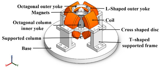
Figure 1.
L-shaped yoke spherical actuator.
Table 2.
Comparison of tilting performance between proposed actuator and other voice coil spherical actuators.
The structural components of the stator and mover of the proposed L-shaped yoke spherical actuator are shown in Figure 2. The outer stator consists of eight coil windings, eight L-shaped outer yokes and upper and lower octagonal yokes. The mover is composed of four arc-shaped axially magnetized permanent magnets and an octagonal column inner yoke. The reason we utilized four axial magnets in the proposed design is to prevent coupling of the electromagnetic forces in the X and Y axes during actuation. The materials of the yoke, the permanent magnet and the supporting fixture are soft steel (Steel 1010), N45H (1.3 T) and non-magnetic aluminum (A6061-T6), respectively. The arrangement of arc-shaped permanent magnets, outer yokes and coils is symmetrical, with an overall maximum diameter of 36 mm, which is determined by considering the production costs and the common size of voice coil spherical actuators [2,25,33,37]. The overall design dimensions and parameters are shown in Figure 3. and Table 3. The outermost height of proposed actuator, , is referenced from the size of multi-functional voice coil spherical actuators [33,34,35]. The design of the upper yoke angle of the proposed voice coil spherical actuator, , is intended to prevent interference between the output shaft and octagonal outer yoke during the actuator’s stroke within ±30°.
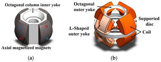
Figure 2.
Basic structure of the actuator: (a) stator and (b) mover.
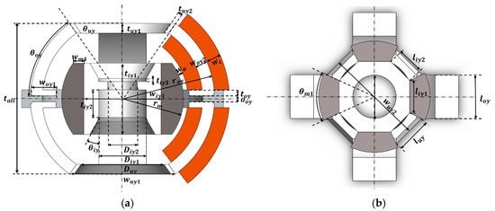
Figure 3.
Design parameters of the actuator: (a) Y-Z cross-sectional view and (b) X-Y cross-sectional view.
Table 3.
Dimensions of proposed L-shaped yoke spherical actuator.
A symmetrical structure is advantageous for simplifying the overall structure and internal magnetic flux pathways while also reducing the costs of the production and manufacturing. The overall structural design, achieved through the unique shape of the L-shaped yoke, enhances the efficiency of magnetic flux utilization, thereby improving the overall performance of the spherical actuator. The magnetic circuit of the stator and mover, when not energized, is shown in Figure 4. Through the arrangement of magnets and the structural design of the yoke, the overall magnetic circuit forms a closed loop.
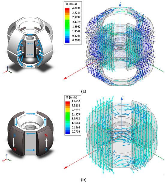
Figure 4.
Magnetic circuit of the actuator: the arrows represent the direction of magnetic field lines. (a) magnetic path of the outer yoke and the mover and (b) magnetic flux generated by the permanent magnet of the mover.
2.2. Preliminary Dimensional Optimization Analysis
The magnitude of the Lorentz force is not only related to the current but also proportional to the strength of the magnetic field it passes through. A preliminary optimization of the L-shaped yoke’s bottom protrusion dimensions was conducted and divided into three lengths 1.7 mm, 2.0 mm and 2.3 mm, as shown in Figure 5. The effect of the bottom protrusion length on the overall magnetic flux distribution is analyzed using magnetic flux distribution diagrams. From Figure 6, the black dashed line represents the coil section where the magnetic field and current interact. Using the relatively faint blue region (B = 0.272~0.36267 Tesla) as a reference for magnetic field strength, it can be observed that the magnetic flux passing through the coil section depends on the length of the bottom protrusion of the L-shaped yoke. Among the three types, the magnetic flux passing through the coil section is smallest for the 1.7 mm type, followed by the 2.0 mm type, and it is largest for the 2.3 mm type. Therefore, under the proposed magnetic circuit structure, the magnitude of magnetic flux passing through the coil section is directly proportional to the length of the bottom protrusion of the L-shaped yoke. Ultimately, considering the overall gap size and uniformity of the spherical actuator, the length of the bottom protrusion is set to 2.3 mm.
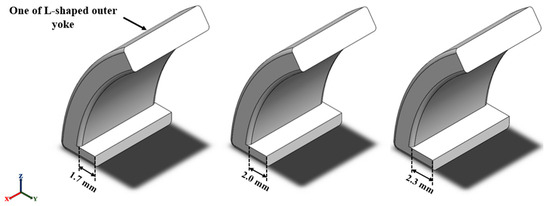
Figure 5.
The dimensions of the bottom protrusion of the L-shaped yoke from left to right are 1.7 mm, 2.0 mm and 2.3 mm, respectively.
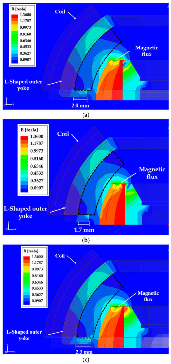
Figure 6.
The magnetic flux distributions of a quarter-spherical actuator with different lengths of L-shaped yoke bottom protrusions in a Y-Z cross-sectional view: (a) 1.7 mm, (b) 2.0 mm and (c) 2.3 mm.
2.3. Operating Principle
The operating principle of the proposed actuator is based on the voice coils, as shown in Figure 7. When coils C1 and C3 carry a current in the direction into the plane, they interact with the vertical magnetic field generated by the N-pole of the permanent magnet. Coils C2 and C4, on the other hand, carry a current in the direction out of the plane, interacting with the vertical magnetic field introduced by the S-pole of the permanent magnet. Four coils (C1 to C4) generate Lorentz forces in a clockwise direction relative to the X-axis, driving the mover to perform a positive tilt motion around the X-axis, as indicated by the red arrows in Figure 7a. Conversely, when the four coils (C1 to C4) carry a reverse current, they generate Lorentz forces in the opposite direction, driving the mover to perform a reverse tilt motion around the X-axis. Similarly, the tilting around the Y-axis can be achieved under the same operating principle, as shown in Figure 7b.
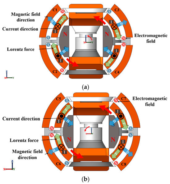
Figure 7.
Operating principle of the actuator: (a) Y-Z cross-section for X-axis tilting and (b) X-Z cross-section for Y-axis tilting.
3. Simulation
3.1. Static Torque Simulation
The proposed spherical actuator differs from those featured in the previous literature by utilizing a design with disassembled coils and an external L-shaped yoke that forms a closed magnetic circuit with the axially magnetized permanent magnets. This design provides a new approach for spherical motors. By interacting with permanent magnets, two sets of coils can be configured to drive the motor with different current directions, as shown in Table 4.
Table 4.
Coil-exciting configuration.
This section will simulate the electromagnetic performance of the L-shaped yoke spherical motor described in this study using ANSYS Maxwell finite element analysis software. The simulation focuses on analyzing the static torque and verifying the feasibility of the initial design. In the simulation, the permanent magnets are set as N45H with an axial magnetization direction; the yoke is configured as Steel 1010 and the coils are made of copper. The air gap between the coils and the permanent magnets is set to 0.8 mm, and the cross-sectional area of the inner side of the coil winding is 24.3 mm2. During simulation, a current of 260 A is applied to this cross-sectional area, resulting in a current density of approximately 10.7 A/mm2. The simulation stroke is set to a bidirectional range of −30° to 30° to ensure effective operation within the target working range.
Figure 8 shows the relationship curve between the actuator torque and the angle based on the Lorentz torque simulation. The horizontal axis represents the angle (°), ranging from −30° to 30°, while the vertical axis represents the torque (N·mm). The curve demonstrates a nonlinear variation in torque within this angle range where the torque first increases as the angle grows, reaching a maximum value of approximately 8.5 N·mm, and then gradually decreases, forming a symmetrical peak distribution. This indicates that the magnitude of the Lorentz torque is significantly influenced by changes in angle. Since the proposed spherical motor has a symmetrical structure with respect to the XZ and YZ planes, we can assume that the torque generated around the X-axis is equal to the torque generated around the Y-axis.
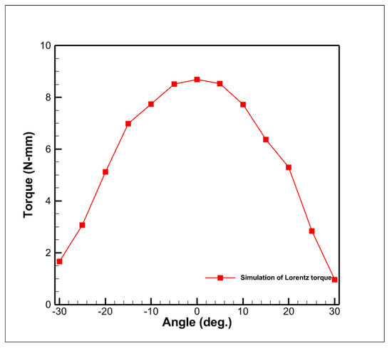
Figure 8.
Output torque simulation analysis.
3.2. Dynamic Modeling
In this section, a mathematical model is established to evaluate the dynamic performance of the proposed L-shaped yoke spherical actuator. It utilizes the Lorentz force generated by the interaction between the permanent magnet and the current in the coil to produce the two-DOF tilting motion. A simplified equivalent circuit equation derived based on Kirchhoff’s circuit laws is shown as (1), where represents the back-electromotive force and can also be expressed as (2), yielding the current relationship in the frequency domain given by (3).
where is the resistance value of the coil winding, is the inductance value, is the applied DC voltage source, is the generated current, is the magnetic field intensity, is the length of the wire placed in the magnetic field, is the radius of rotation of the ball-type motor, is the velocity, is the deflection angle, is the back-electromotive force torque constant and represents the deflection axes X and Y of the rotating component. The output torque relationships are shown as follows:
where represents the total torque experienced at the center of mass of the rotating component, composed of the current torque and the transient torque , is the current torque constant and is the detent torque constant. Substituting the aforementioned (3), the dynamic equations of the L-shaped yoke spherical actuator and the transfer function G(s) of the actuator system are obtained as follows:
The MATLAB Simulink R2024a software is utilized in conjunction with the mathematical model of the L-shaped yoke spherical actuator to establish a dynamic model for the actuator, enabling the analysis of its dynamic characteristics. The parameters of the spherical actuator are outlined in Table 5. Here, the torque constant is defined as the average output torque at an input current of 1A, while the detent torque represents the change in torque when no current is applied. Both values are obtained from the preceding 3D finite element analysis.
Table 5.
Specifications for tilting.
The open-loop Bode plot of this system is shown in Figure 9, indicating that the bandwidth of the open-loop system for the proposed spherical actuator is approximately 14 Hz.
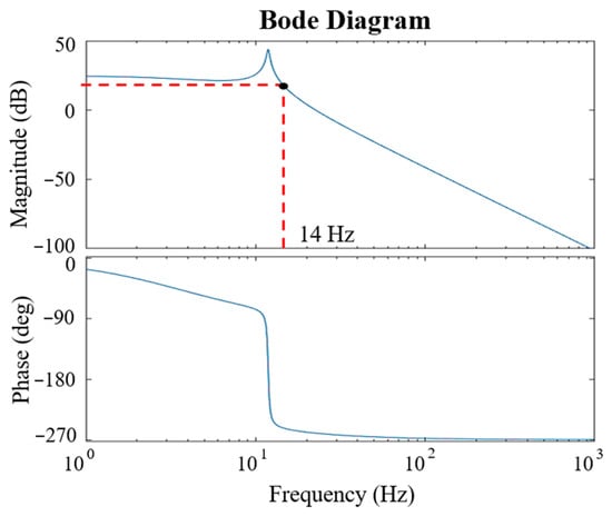
Figure 9.
Open-loop bode diagram.
We take Hall sensors as the signal source receiver component and employ a PID control system as the closed-loop control method, as shown in Figure 10, where represents the target angle, is the system’s output angle and the error between them is fed back to the PID controller for dynamic compensation. The control parameters, obtained through initial iterative tuning, are presented in Table 6. In the table, stands for proportional gain, for integral gain and for derivative gain.
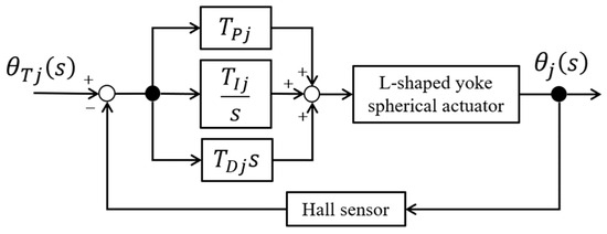
Figure 10.
Block diagram of the PID control system.
Table 6.
PID control gain table.
The Bode diagram of the closed-loop control with PID control, as shown in Figure 11, indicates that the bandwidth of the proposed spherical actuator controlled by the closed-loop system is approximately 155 Hz. The input consists of a step signal with a target angle of 1°. The resulting position signal is shown in Figure 12. It can be observed that the proposed spherical actuator reaches a stable state after 0.8 s, closely following the target angle signal. Therefore, it can be concluded that the L-shaped yoke spherical actuator proposed in this paper is capable of controlling rotational motion around both axes. Nevertheless, the actual control of the spherical actuator is still subject to factors such as friction resulting from size discrepancies. Hence, practical control parameters still need to be iteratively adjusted based on experimental results.
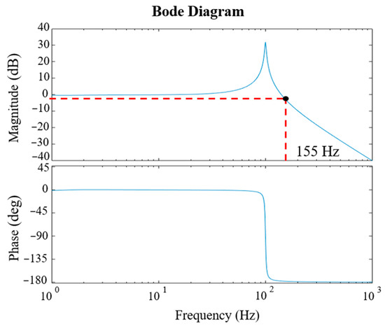
Figure 11.
Closed-loop Bode diagram.
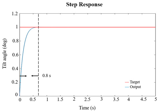
Figure 12.
Closed-loop system step response diagram.
4. Experiment and Verification
4.1. Prototype
Through the previously mentioned L-shaped yoke spherical actuator, a prototype has been designed and fabricated, as shown in Figure 13. Figure 13a shows the assembly diagram of the mover of the prototype, which is internally supported by an IGUS KGLM-02 bearing. Figure 13b depicts the stator of the prototype. The yokes and jigs were machined and manufactured using precision turning and a milling machine. Considering the budget, the coil sets are hand-wound and secured with varnish. The magnets were fabricated and magnetized by TESLAR TECHNOLOGY, Taichung 408010, Taiwan, a magnet manufacturing company.
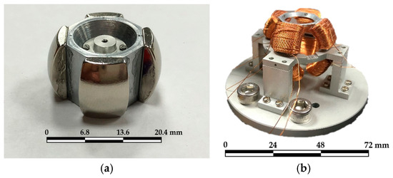
Figure 13.
Prototype of the proposed actuator: (a) mover and (b) stator.
4.2. Experimental Setup
The functionality of the proposed spherical actuator was evaluated through torque measurement experiments. Torque measurements were taken at different positions of the spherical actuator. The experimental setup, as shown in Figure 14, involved the use of a data acquisition unit (NI USB-6211) to receive signals from a six-axis sensor (F/T Sensor: Nano17-E). The torque values sensed by the six-axis sensor were observed and recorded on a computer to quantify the Lorentz forces generated by the interaction between the permanent magnets and the excited coils.
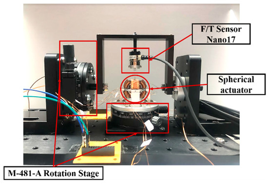
Figure 14.
Photograph of torque experiment setup.
A comparison between the simulation and experimental data is shown in Figure 15. In Figure 15, the coils (C1 to C4) responsible for generating tilting around the X-axis were supplied with 0.72 A per turn by the power supply. The experimental data show that the average current torque was 3.15 N·mm, with a noticeable decrease in the range from ±20° to ±30°. The maximum overall value was 5.19 N·mm at 0°, and the minimum was 0.15 N·mm at 30°. Due to the influence of the external measurement setup, there were discrepancies between the experimental results and the simulated values. One of the main reasons for these discrepancies can be contributed to imperfections in the IGUS KGLM-02 bearing, a commercial plastic production with great tolerance. It induces a great deal of friction between the mover and stator of the proposed prototype. However, the overall trends of the curves align with the current torque simulation results, providing preliminary evidence of the feasibility of the proposed structure. Additionally, the measurement method we used focused solely on the Lorentz torque, ignoring the attractive force between the magnets and yokes. When considering both the attractive force and the induced magnetic field effects of the coil [16,38], the resulting actuator output torque, as shown in Figure 16, increases by 9.38 N·mm. The actuator generates positive torque from −15° to +30° when a positive current is applied to the X-axis. In the future, we plan to conduct more refined experiments and controls on the prototype, leveraging the outcomes of this paper to develop multi-DOF and miniaturized spherical actuators.
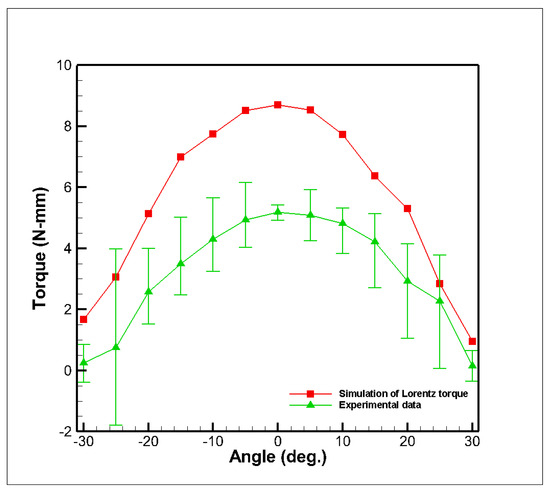
Figure 15.
Experimental and simulated results of tilting around the X-axis and Y-axis.
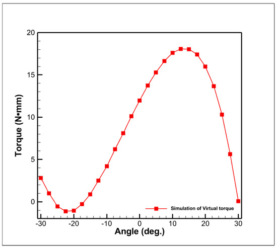
Figure 16.
Simulated output torque with detailed considerations.
5. Conclusions
This paper introduces a novel 2-DOF L-shaped yoke spherical actuator, highlighting the unique features and advantages of voice coil spherical motors. A performance comparison between the proposed spherical actuator and existing design is presented, demonstrating the potential benefits of energy saving achieved through the use of various coil configurations. Additionally, a dynamic model was developed to simulate the behavior of the proposed actuator, and the results were validated through the fabrication of a prototype for preliminary experimental verification. The prototype has a diameter of 36 mm and 2-DOF tilting stroke of ±30°. Despite some discrepancies between the experimental and simulated results, the findings confirm the feasibility and efficiency of the proposed actuator design, offering significant potential for future applications, such as robotic eye systems, image stabilization systems and posture control for in-vehicle speakers and microphones.
Author Contributions
Conceptualization, Y.-W.H., M.-F.C. and C.-S.L.; formal analysis, Y.-W.H. and M.-F.C.; methodology, Y.-W.H. and C.-S.L.; validation, Y.-W.H.; investigation Y.-W.H., Y.-M.C., H.-W.C. and C.-S.L.; simulation, Y.-W.H., Y.-M.C. and H.-W.C.; writing—original draft preparation, Y.-W.H.; writing—review and editing, C.-S.L., Y.-M.C. and H.-W.C.; software, Y.-W.H.; supervision, C.-S.L.; project administration, C.-S.L.; funding acquisition, C.-S.L. All authors have read and agreed to the published version of the manuscript.
Funding
This research was funded by the National Science and Technology Council of Taiwan under Grant Nos. NSTC 110-2221-E-006-162-MY2.
Data Availability Statement
Data are contained within the article.
Acknowledgments
Ansys Inc. is thanked for providing the ANSYS academic partner program.
Conflicts of Interest
The authors declare no conflicts of interest.
References
- Tsukano, M.; Sakaidani, Y.; Hirata, K.; Niguchi, N.; Maeda, S.; Zaini, A. Analysis of 2-Degree of Freedom Outer Rotor Spherical Actuator Employing 3-D Finite Element Method. IEEE Trans. Magn. 2013, 49, 2233–2236. [Google Scholar] [CrossRef]
- Lin, Y.-H.; Liu, C.-S.; Yeh, C.-N. Design and Simulation of Novel 3-DOF Spherical Voice Coil Motor. Actuators 2021, 10, 155. [Google Scholar] [CrossRef]
- Liu, C.-S.; Lin, Y.-H.; Yeh, C.-N. Analytical Investigation on Torque of Three-Degree-of-Freedom Electromagnetic Actuator for Image Stabilization. Appl. Sci. 2021, 11, 6872. [Google Scholar] [CrossRef]
- Li, H.; Luo, J.; Huang, C.; Huang, Q.; Xie, S. Design and Control of 3-DoF Spherical Parallel Mechanism Robot Eyes Inspired by the Binocular Vestibule-ocular Reflex. J. Intell. Robot. Syst. 2015, 78, 425–441. [Google Scholar] [CrossRef]
- Zhang, X.; Zhang, G.; Nakamura, K.; Ueha, S. A robot finger joint driven by hybrid multi-DOF piezoelectric ultrasonic motor. Sens. Actuators A Phys. 2011, 169, 206–210. [Google Scholar] [CrossRef]
- Kim, D.-K.; Yoon, H.; Kang, W.-Y.; Kim, Y.-B.; Choi, H.-T. Development of a spherical reaction wheel actuator using electromagnetic induction. Aerosp. Sci. Technol. 2014, 39, 86–94. [Google Scholar] [CrossRef]
- Nishiura, Y.; Hirata, K.; Oya, K. Optimization of stator pole arrangement for 3-DOF spherical actuator using genetic algorithm. In Proceedings of the 2015 IEEE International Magnetics Conference (INTERMAG), Beijing, China, 11–15 May 2015; p. 1. [Google Scholar]
- Bai, S.; Li, X.; Angeles, J. A review of spherical motion generation using either spherical parallel manipulators or spherical motors. Mech. Mach. Theory 2019, 140, 377–388. [Google Scholar] [CrossRef]
- Yang, S.; MacLachlan, R.A.; Riviere, C.N. Manipulator Design and Operation of a Six-Degree-of-Freedom Handheld Tremor-Canceling Microsurgical Instrument. IEEE/ASME Trans. Mechatron. 2015, 20, 761–772. [Google Scholar] [CrossRef] [PubMed]
- Fusayasu, H.; Masuyama, Y.; Hirata, K.; Niguchi, N.; Takahara, K. Analysis Accuracy in Positioning Calculation for Three-Degree-of-Freedom Spherical Actuator. IEEE Trans. Magn. 2021, 57, 1–4. [Google Scholar] [CrossRef]
- Gan, L.; Pei, Y.; Chai, F. Tilting Torque Calculation of a Novel Tiered Type Permanent Magnet Spherical Motor. IEEE Trans. Ind. Electron. 2020, 67, 421–431. [Google Scholar] [CrossRef]
- Chen, D.; Song, A.; Tian, L.; Ouyang, Q.; Xiong, P. Development of a Multidirectional Controlled Small-Scale Spherical MR Actuator for Haptic Applications. IEEE/ASME Trans. Mechatron. 2019, 24, 1597–1607. [Google Scholar] [CrossRef]
- Seyfarth, G.; Bhatia, A.; Sassnick, O.; Shomin, M.; Kumagai, M.; Hollis, R. Initial results for a ballbot driven with a spherical induction motor. In Proceedings of the 2016 IEEE International Conference on Robotics and Automation (ICRA), Stockholm, Sweden, 16–21 May 2016; pp. 3771–3776. [Google Scholar]
- Yan, L.; Duan, Z.; Zhang, Q.; Qiao, H.; Gerada, C. Development and structure of multi-DOF spherical induction motor. In Proceedings of the 2018 13th IEEE Conference on Industrial Electronics and Applications (ICIEA), Wuhan, China, 31 May–2 June 2018; pp. 2831–2835. [Google Scholar]
- Fernandes, J.F.P.; Branco, P.J.C. The Shell-Like Spherical Induction Motor for Low-Speed Traction: Electromagnetic Design, Analysis, and Experimental Tests. IEEE Trans. Ind. Electron. 2016, 63, 4325–4335. [Google Scholar] [CrossRef]
- Dehez, B.; Galary, G.; Grenier, D.; Raucent, B. Development of a spherical induction motor with two degrees of freedom. IEEE Trans. Magn. 2006, 42, 2077–2089. [Google Scholar] [CrossRef]
- Sakaidani, Y.; Hirata, K.; Niguchi, N. Characteristics Analysis of a 2-D Differentially Coupled Magnetic Actuator. IEEE Trans. Magn. 2016, 52, 1–4. [Google Scholar] [CrossRef]
- Yan, L.; Chen, I.-M.; Lim, C.K.; Yang, G.; Lin, W.; Lee, K.-M. Design and analysis of a permanent magnet spherical actuator. IEEE/ASME Trans. Mechatron. 2008, 13, 239–248. [Google Scholar] [CrossRef]
- Park, H.-J.; Lee, H.-J.; Cho, S.-Y.; Ahn, H.-W.; Lee, K.-D.; Park, C.-Y.; Won, S.-H.; Lee, J. A Performance Study on a Permanent Magnet Spherical Motor. IEEE Trans. Magn. 2013, 49, 2307–2310. [Google Scholar] [CrossRef]
- Cho, S.; Lim, J.-S.; Oh, Y.J.; Jeong, G.; Kang, D.-W.; Lee, J. A Study on Output Characteristics of the Spherical Multi-DOF Motor According to the Number of Phases and Pole Pitch Angles. IEEE Trans. Magn. 2018, 54, 1–5. [Google Scholar] [CrossRef]
- Lee, H.J.; Park, H.J.; Ryu, G.H.; Oh, S.Y.; Lee, J. Performance Improvement of Operating Three-Degree-of-Freedom Spherical Permanent-Magnet Motor. IEEE Trans. Magn. 2012, 48, 4654–4657. [Google Scholar] [CrossRef]
- Chen, Q.; Yang, X.; Zhong, G.; Zeng, B.; Zhao, S.; Cao, J. Design and Analysis of Double Stator Swing Rotating Permanent Magnet Spherical Motor. IEEE Trans. Magn. 2022, 58, 1–12. [Google Scholar] [CrossRef]
- Mashimo, T.; Toyama, S.; Ishida, H. Design and implementation of spherical ultrasonic motor. IEEE Trans. Ultrason. Ferroelectr. Freq. Control. 2009, 56, 2514–2521. [Google Scholar] [CrossRef] [PubMed]
- Huang, Z.; Shi, S.; Chen, W.; Wang, L.; Wu, L.; Liu, Y. Development of a novel spherical stator multi-DOF ultrasonic motor using in-plane non-axisymmetric mode. Mech. Syst. Signal Process. 2020, 140, 106658. [Google Scholar] [CrossRef]
- Deng, J.; Liu, Y.; Chen, W.; Yu, H. A XY Transporting and Nanopositioning Piezoelectric Robot Operated by Leg Rowing Mechanism. IEEE/ASME Trans. Mechatron. 2019, 24, 207–217. [Google Scholar] [CrossRef]
- Hoshina, M.; Mashimo, T.; Toyama, S. Development of spherical ultrasonic motor as a camera actuator for pipe inspection robot. In Proceedings of the 2009 IEEE/RSJ International Conference on Intelligent Robots and Systems (IROS 2009), St. Louis, MO, USA, 11–15 October 2009; pp. 2379–2384. [Google Scholar]
- Kim, H.; Kim, H.; Ahn, D.; Gweon, D. Design of a new type of spherical voice coil actuator. Sens. Actuators A Phys. 2013, 203, 181–188. [Google Scholar] [CrossRef]
- Chu, J.; Niguchi, N.; Hirata, K. Design and analysis of a new spherical actuator. In Proceedings of the 2015 IEEE International Magnetics Conference (INTERMAG), Beijing, China, 11–15 May 2015; p. 1. [Google Scholar]
- Heya, A.; Hirata, K.; Ezaki, S.; Ota, T. Dynamic analysis of a new Three-Degree-of-Freedom actuator for image stabilization. IEEE Trans. Magn. 2017, 53, 1–4. [Google Scholar] [CrossRef]
- Heya, A.; Hirata, K. Motion Control of Three-Degree-of-Freedom Spherical Actuator Driven by Four-Phase. J. Jpn. Soc. Appl. Electromagn. Mech. 2022, 30, 167–172. [Google Scholar] [CrossRef]
- Heya, A.; Hirata, K.; Niguchi, N. Dynamic Modeling and Control of Three-Degree-of-Freedom Electromagnetic Actuator for Image Stabilization. IEEE Trans. Magn. 2018, 54, 1–5. [Google Scholar] [CrossRef]
- Kim, H.Y.; Kim, H.; Gweon, D.-G.; Jeong, J. Development of a novel spherical actuator with two degrees of freedom. IEEE/ASME Trans. Mechatron. 2015, 20, 532–540. [Google Scholar] [CrossRef]
- Heya, A.; Hirata, K. Experimental Verification of Three-Degree-of-Freedom Electromagnetic Actuator for Image Stabilization. Sensors 2020, 20, 2485. [Google Scholar] [CrossRef] [PubMed]
- Kuribayashi, S.; Heya, A.; Hirata, K.; Kurita, M. A Six-Coil Two-Degree-of-Freedom Actuator Driven by Three-Phase. In Proceedings of the 2021 24th International Conference on Electrical Machines and Systems (ICEMS), Gyeongju, Republic of Korea, 31 October–3 November 2021; pp. 79–82. [Google Scholar]
- Heya, A.; Nakata, Y.; Ishiguro, H.; Hirata, K. Two-Degree-of-Freedom Actuator for Robotic Eyes. In Proceedings of the 2020 International Conference on Electrical Machines (ICEM), Gothenburg, Sweden, 23–26 August 2020; pp. 735–740. [Google Scholar]
- Kim, H.; Kim, H.; Gweon, D. Magnetic field analysis of a VCM spherical actuator. Sens. Actuators A Phys. 2013, 195, 38–49. [Google Scholar] [CrossRef]
- Yeh, C.N.; Huang, W.S.; Chung, H.W.; Liu, C.S. Design of two-degree-of-freedom spherical actuator with X-shaped yokes. Microsyst. Technol. 2025. [Google Scholar] [CrossRef]
- Valagiannopoulos, C.A. Single-series solution to the radiation of loop antenna in the presence of a conducting sphere. Prog. Electromagn. Res. 2007, 71, 277–294. [Google Scholar] [CrossRef]
Disclaimer/Publisher’s Note: The statements, opinions and data contained in all publications are solely those of the individual author(s) and contributor(s) and not of MDPI and/or the editor(s). MDPI and/or the editor(s) disclaim responsibility for any injury to people or property resulting from any ideas, methods, instructions or products referred to in the content. |
© 2025 by the authors. Licensee MDPI, Basel, Switzerland. This article is an open access article distributed under the terms and conditions of the Creative Commons Attribution (CC BY) license (https://creativecommons.org/licenses/by/4.0/).