Abstract
This paper presents the design of a sliding mode controller to compensate hysteresis nonlinearity and achieve precision motion tracking for a novel piezoelectric tip/tilt platform driven by a PZT actuator. The sliding mode control scheme is based on the unique physical characteristics of the piezoelectric tip/tilt platform. The proposed scheme effectively guides the platform state onto a predefined sliding surface and ensures its sustained movement along this manifold. This approach reduces tracking errors compared to conventional methodologies. The stability of the sliding mode control scheme is demonstrated by the Lyapunov theory framework. It achieves precise motion control with minimal tracking error on a piezoelectric tip/tilt platform. The properties of the controller have been confirmed through experimental tests. The proposed control scheme enhances the robust tracking and stability performance on the piezoelectric tip/tilt platform, outperforming traditional control schemes. Compared with the P562.6CD produced by PI Germany, the proposed innovative approach not only boosts the platform’s resolution by 32% but also implements a 33% reduction in cost.
1. Introduction
As research on micro/nanopositioning technology deepens, the application of the micro/nanopositioning stage extends to optical instrumentation [1,2], nanorobotics [3], biomedicine [4,5], and precision machining [6]. PZT actuators have the advantages of a small size [7], being silent [8], a shorter response time, and so on. Then, they are usually employed as actuators for the micro/nanopositioning stage. However, the hysteresis property [9], the nonlinearity between the input voltage and the response, and the hysteresis characteristic properties of piezoelectric materials pose great challenges to micro/nanopositioning technology [10]. Therefore, suitable control schemes must be adopted to improve the accuracy of micro/nanopositioning technology. Nowadays, the main control strategies explored in the literature include neural network control [11], damping-enabled control [12], PID controllers [13], and sliding mode control [14].
The piezoelectric tip/tilt platform, as a kind of deflection platform driven by a PZT actuator applied in the micro/nanopositioning technique, has the virtues of a small scanning angle, high resolution, and good linearity. It is often used for optical deflection, beam tracking, and stabilization, as well as in other applications requiring small-angle deflection. The platform is designed to operate in low-frequency and light-load conditions. The intrinsic hysteresis nonlinearity of the PZT actuator poses a challenge to the platform’s precise positioning. The new piezoelectric tip/tilt platform proposed in this paper offers small displacements through flexure hinge. The dilator incorporated into the platform’s design imparts a pronounced nonlinearity to the platform’s motion dynamics. It tends to oscillate during testing, resulting in unsatisfactory positioning accuracy. In addition, the large acceleration and high-frequency control signals complicate control and destabilize the system, leading to large positioning errors and poor interference immunity. In general, the primary challenges encountered in the deployment of the platform can be categorized as follows. (1) Nonlinear issues arise from two main sources: firstly, they are intrinsic to the properties of the PZT actuator’s material, and secondly, they are influenced by the structural attributes that have been specifically tailored for the platform. (2) Ensuring the system’s stability is another critical challenge that must be addressed. As open loops cannot solve the above drawback, it is essential to select an appropriate control strategy to verify the stage’s performance. The newly designed piezoelectric tip/tilt platform shares structural similarities with the P562.6CD model. The P562.6CD is offered by PI Corporation. The P562.6CD’s prohibitive cost hinders its broad implementation. This research endeavored to introduce a novel control strategy that substantially diminishes the operational expenses of the platform, without compromising its performance relative to the P562.6CD. The existing equipment’s cost is estimated at 33% of the P562.6CD’s, thereby underscoring the criticality of the proposed control strategy’s performance on the piezoelectric tip/tilt platform. To substantiate the proposed controller’s performance on the piezoelectric tip/tilt platform, a comparative analysis of the resolution between our piezoelectric tip/tilt platform and the P562.6CD was conducted. Furthermore, a comparative evaluation was conducted regarding stability and tracking performance using studies from leading industry peers as a reference point.
The proportional–integral–derivative (PID) controller, as the most widely used control strategy in industry, is mature, simple, and easy to understand. Hence, PID is often the first choice for industrial control and remains a traditional strategy. But the PID controller is less resistant to interference in practice. And the uncertainty of the system makes its control unstable [15]. At the same time, the piezoelectric tip/tilt platform is very sensitive in the values of the integral term and the differential term. And, the PID control is prone to oscillate the system, which cause the performance to deteriorate rapidly. Sliding mode control is a variable structure control strategy that forces the system to follow a predetermined state. This strategy is employed when there are discrepancies between the deterministic model and the actual controlled object, particularly regarding object parameters and uncertain external disturbances [16]. Sliding mode control is a nonlinear control strategy that achieves fast responses and robustness of the system by creating a sliding surface in the system state space. The predetermined trajectories are independent of the perturbations. In addition, the response is fast and simple to physically implement, which is commonly used as the control strategy for PZT actuators [17,18,19,20,21]. Sliding mode control can prevent oscillations in the piezoelectric tip/tilt platform and enhance system stability. In addition, the suppression for the chattering of sliding mode control has obtained wide attention [22,23,24,25,26]. A drawback of the sliding mode control scheme is the chattering phenomenon, which arises from its discontinuous nature. On the one hand, the chattering will lead to reductions in the control accuracy and the life of the piezoelectric tip/tilt platform. On the other hand, the large acceleration generated by the chattering will make the piezoelectric tip/tilt platform oscillate violently, which leads to the instability of the system. So, the reduction in the effect of the chattering is essential to the implementation of the control strategy.
There is limited research on the control scheme for the piezoelectric tip/tilt platform. And there is a lack of discussion on their control strategies [27]. What can be used as a reference is the piezoelectric steering, which mirrors the motion situation, such as in PID, closed-loop, and voltage control [28,29,30]. Therefore, the performance of the sliding mode control strategy needs to be tested on a piezoelectric tip/tilt platform.
Subsequently, a sliding mode control scheme for the piezoelectric tip/tilt platform is proposed to achieve precision motion tracking control. The scheme does not use the sign function as a nonlinear control term. And the scheme mitigates the chattering phenomenon of the sliding mode control by optimizing the thickness of the boundary layer based on the saturation function. The stability of the system is proved based on Lyapunov’s theory. And the feasibility of the scheme is verified by experimental tests.
The main contribution of this study is the design of a sliding mode control strategy for a novel piezoelectric tip/tilt platform. The main contents of this paper are described as follows. Section 2 illustrates the process of building the dynamics model. Section 3 presents the design of the sliding mode controller as well as illustrates the suppression strategy for its chattering phenomenon. The experimental equipment and the parameter identification are described in Section 4. The experimental results are shown in Section 5, experimentally obtained to verify the controller performance, and Section 6 summarizes the work of this study.
2. Dynamics Modeling
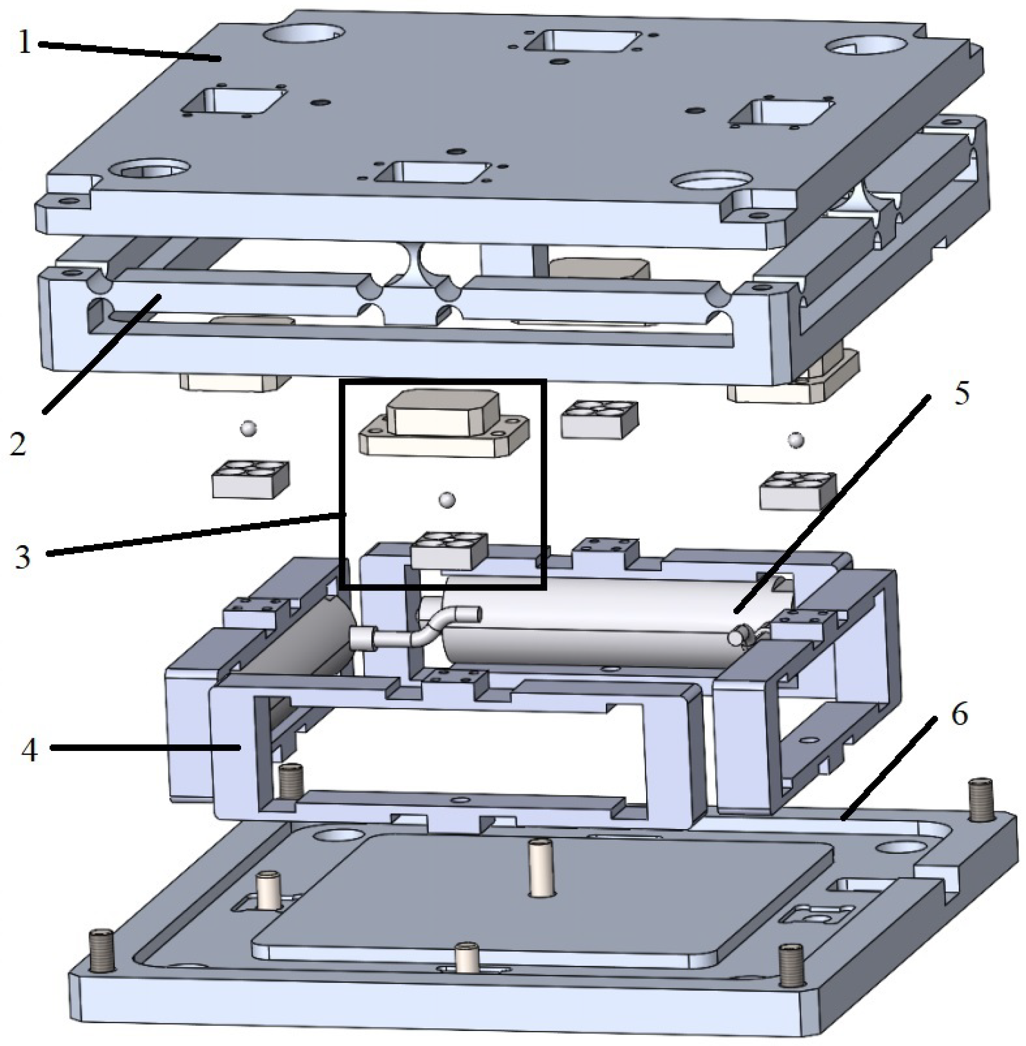
The novel platform is a two-dimensional platform that rotates in the X and Y directions, and the structure of the platform is shown in Figure 1. The structures, from one to six, are as follows:
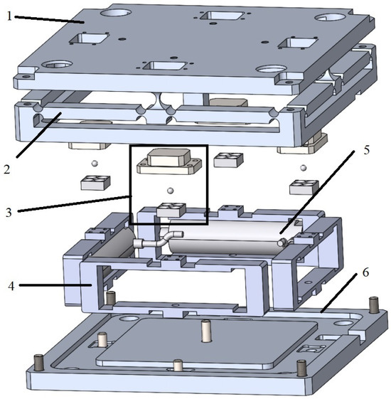
Figure 1.
The structure of the novel piezoelectric tip/tilt platform: 1. platform, 2. guiding mechanism, 3. U joint, 4. bridge amplifier, 5. PZT actuator, 6. base board.
- Platform: it provides a flat and stable working surface.
- Guiding mechanism: the guiding mechanism is responsible for ensuring the linearity of the platform’s motion. The mechanism accurately directs the motion of the moving parts, minimizing deviations from the intended linear path.
- U joint: the U joint is a pivotal component that provides rotational freedom in two dimensions. It allows for the movement in two planes at the same time, enhancing the flexibility and range of motion of the piezoelectric tip/tilt platform.
- Bridge amplifier: the bridge amplifier functions to enhance the piezoelectric tip/tilt platform’s motion. It amplifies the travel distance and also enables the conversion of motion direction.
- PZT actuator: The PZT actuator is a piezoelectric actuator that generates precise displacements. It is capable of providing minute steps in movement, which is essential for the high-precision micro/nanopositioning stage.
- Base board: the base board is the foundational structure of the piezoelectric tip/tilt platform, serving as its base. It supports the entire system, providing stability and anchoring the platform and other components.
In general, the dynamics model of the system can be expressed as follows:
where t represents the time variable. u is the input driving voltage. x denotes the output displacement. and are the intrinsic parameters of the system representing the mass, damping coefficient, stiffness, and nominal voltage-to-force coefficient, respectively. indicates the lumped disturbance of the external disturbances and hysteresis effects.
Assumption 1.
The lumped disturbance is bounded as
where the constant .
According to the above model, the control problem can be formulated to achieve the tracking of the ideal motion trajectory under the lumped disturbance . In order to achieve precise motion control, a sliding mode control scheme was designed, as shown in Section 3.
3. Sliding Mode Controller Design
This section covers the design of the sliding mode control scheme. The goal of the scheme is to minimize the tracking error. The tracking error is defined as
where is the desired position trajectory, and is the actual position trajectory.
Based on the tracking error e, a proportional derivative type of sliding surface is selected in this study, which is defined as
where , and it satisfies the Hurwitz condition. Then, the equation of the above dynamics model can be rewritten as
Theorem 1.
In forming Formulas (5) and (7), it can be obtained that
and in forming Formulas (8) and (6), the controller can be deduced as
Proof.
According to the following Lyapunov function candidate, demonstrating the stability of the designed controller (9),
Then,
□
Therefore, Lyapunov function candidate (10) is negative definite. In referring to the LaSalle invariant set theorem, the system is progressively stabilized. The proof of the stability of this system is completed.
Remark 1.
It can be seen from (9) that the second-order derivative of the ideal position is used for the controller. In this control system, the ideal position is defined in advance; therefore, is assumed to be available.
Remark 2.
In reaching law (6), to ensure fast convergence while weakening the chattering, we should increase p while decreasing ε. However, due to the discontinuity of the sign function and the large p-value chosen in the actual design, the chattering phenomenon can be very obvious. Therefore, in order to mitigate the chattering, the saturation function is used instead of the sign function.
where is the boundary layer, .
4. Experimental Setup
4.1. Experimental Equipment
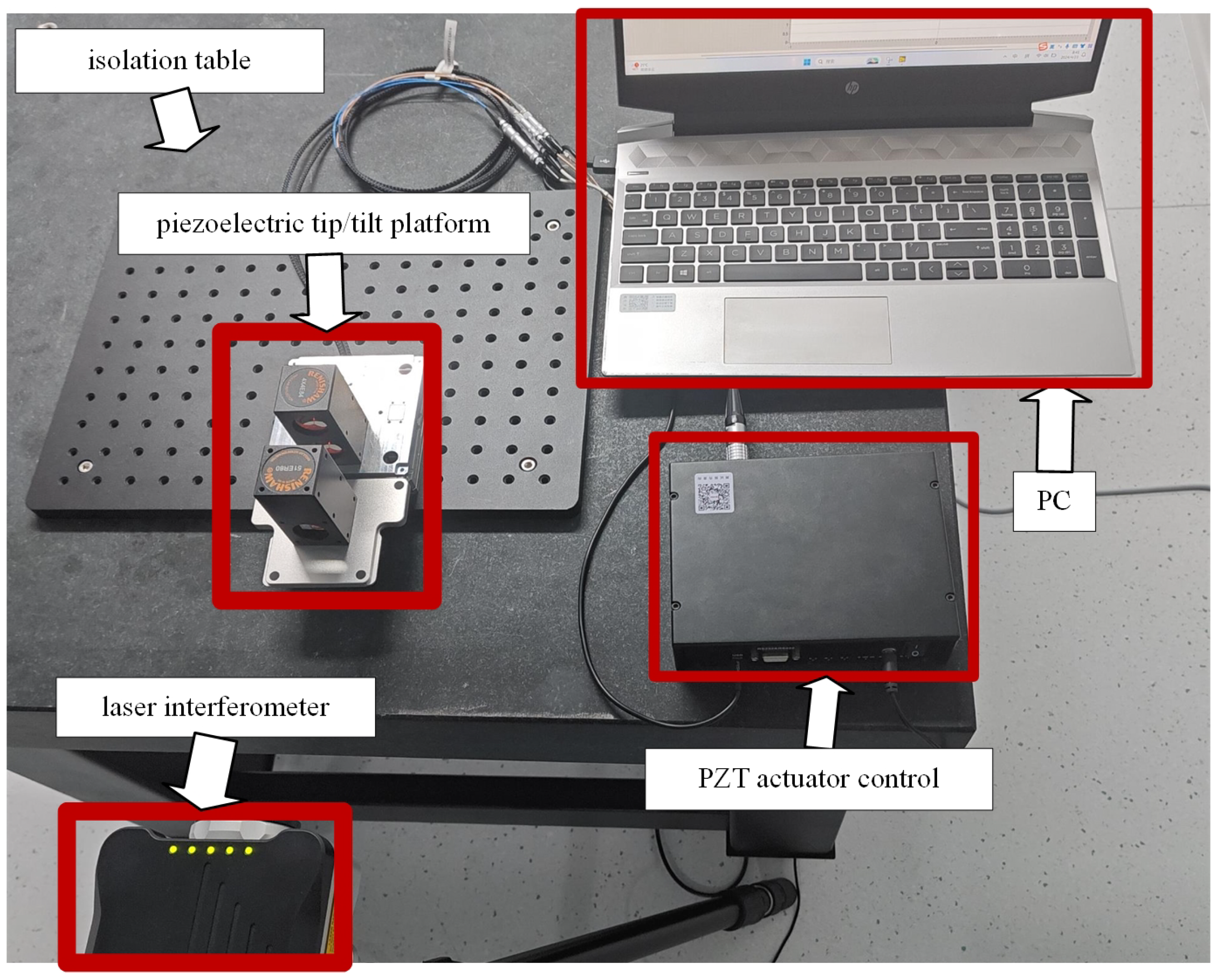
The experimental setup is shown in Figure 2. The plant is a novel piezoelectric tip/tilt platform driven by a PZT actuator (model: PSt150/7/40 vs12, from core morrow), and resistive strain gauges for measuring position feedback are built into the PZT actuator. The PZT actuator is actuated by a PZT actuator controller (model: E70, from core morrow), and the plant can be driven by the PZT actuator controller to achieve a maximum displacement of 38 μm. The experiments were conducted on a vibration isolation table (model: ZDT-B-MOT, from Liansheng, Nanchang, China). The angle of the platform deflection was measured using a laser interferometer (model: XL-80, from Renishaw Glaucestershire, London, UK). The data were collected by the software provided by Renishaw. The experiment involved the generation of ideal position signals through LabVIEW 2020 and the control algorithm was implemented using this software. The resistive strain gauge sensor collected the voltage data and fed it back to the PZT actuator controller. Then, this controller transmitted the data to LabVIEW.

Figure 2.
Equipment setup of a piezoelectric tip/tilt platform.
4.2. System Identification
In combining the parameters of the above components and the use of the system identification toolbox in MATLAB,2016a the key data for the controller system in Equation (1) can be obtained in Table 1.

Table 1.
Parameters of dynamics model.
4.3. Controller Setup
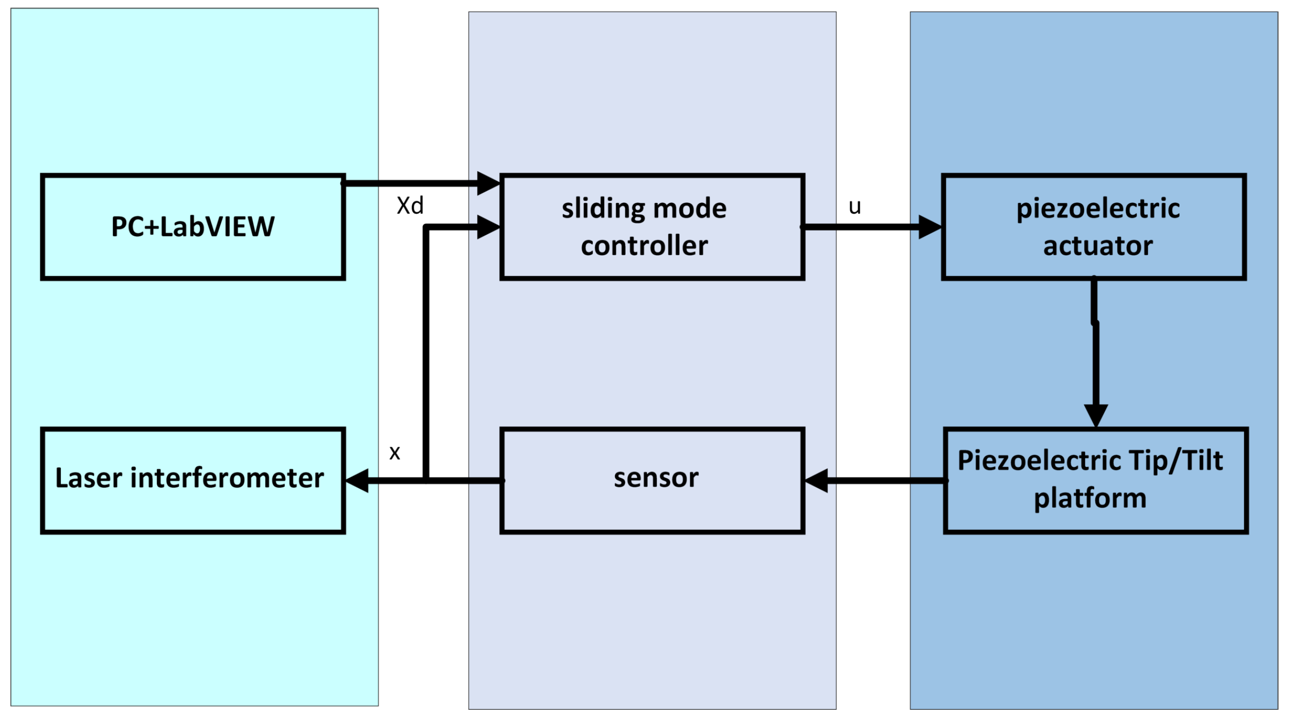
In order to illustrate the effectiveness of the control scheme designed, comparative experiments were conducted to compare three control schemes, including open-loop, PID control, and sliding mode control. The overall control scheme of sliding mode control on the piezoelectric tip/tilt platform is shown in Figure 3.
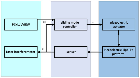
Figure 3.
Sliding mode control scheme for a piezoelectric tip/tilt platform.
The parameters of the proposed PID controller were proportional gain, integral gain, and differential gain, which were set to 0.0832, 0.0843, and , respectively. The acquisition of parameters was achieved through an extensive manual tuning process.
The parameters of the proposed sliding mode control were selected as , p = 32,488, , and . The selection of the sliding mode parameters was conducted through numerical simulation combined with experimental adjustment.
The ideal signal designed for the experiment is shown below:
where t is the time variable in units of ms, and A denotes the amplitude in units of V. And f denotes the frequency in units of Hz. In this experiment, the amplitude A was 5 V. The frequency was 0.05 Hz and 0.1 Hz.
In order to quantify the results of the tracking for comparison purposes, three error indexes were defined in advance as follows:
where indicates the relative error of linearity, denotes the root mean square, represents the maximum absolute error, and N is the number of data points.
4.4. Experimental Test Steps
The experimental test was conducted in the following steps:
- (1)
- Assemble the piezoelectric tip/tilt platform on the isolation table to prevent the large shaking of environment.
- (2)
- Connect the PZT actuator controller to the piezoelectric tip/tilt platform, the controller to computer, and the laser interferometer to the computer.
- (3)
- Turn on the power and air supply of the isolation table. And the experiment should be carried out only when the table is ready. Connect the laser interferometer power supply and preheat the laser interferometer.
- (4)
- Wait for the laser interferometer to reach the operating temperature. Adjust the laser interferometer until five stable green lights appear.
- (5)
- Open the LabVIEW 2020 software and the written program. Connect the computer and PZT actuator controller. And start the experimental test.
5. Results and Discussion
5.1. Tracking Error Testing Results
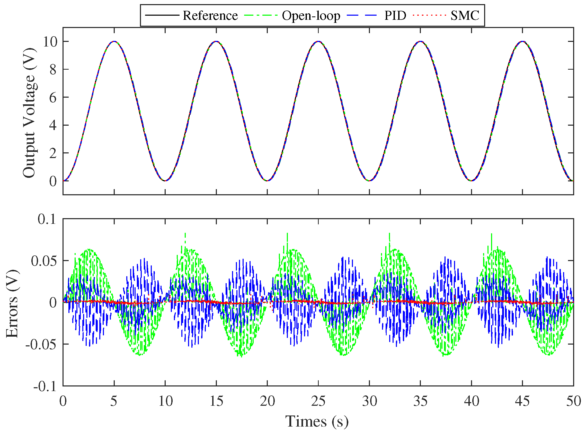
Table 2 shows the statistical results of the experiment. The term ‘Hybrid’ in the table refers to all the frequencies above. In this table, the sliding mode control scheme was superior to the PID scheme at the same frequency. The PID control scheme performs better than the open-loop scheme. In terms of the maximum absolute error , PID and the sliding mode control can suppress the tracking error. The sliding mode control scheme exhibits a maximum absolute error that is 20% of that observed in the PID scheme, thereby reducing errors by 80% compared to the PID. The linear relative errors of all three controllers are below 2%. In the travel of 10 V, the linearity relative error of the sliding mode control strategy in this experiment was 0.194% at 0.1 Hz. In article [31], the linearity relative error was 0.256% at 0.1 Hz based on an online neural network sliding mode in the travel of 2 μm. The result in our study is only of that in article [31]. In addition, the root mean square error is only 0.001 V. The root mean square error of the sliding mode control scheme is equivalent to 4.8% of that of PID and 2.7% of that of the open-loop scheme. In fact, 98% of the error of the sliding mode control strategy at 0.1 Hz is less than 0.005 V. Compared with the root mean square at the same frequency, the sliding mode control scheme has the best stability, followed by PID, and finally the open-loop scheme.
Table 2.
Sinusoidal tracking errors of different controllers.
Figure 4 and Figure 5 show the tracking results of sinusoidal tracking with three different controllers at 0.05 Hz and 0.1 Hz, respectively. Based on these two figures, we can analyze the main causes of error. (1) The system’s time delay: This delay causes a phase difference between the input and output sinusoidal curves. Subtracting two sinusoidal curves with phase difference at the same frequency results in another sinusoidal curve. Hence, all error patterns appear sinusoidal. (2) The effects of external disturbances, platform structures, and the chattering phenomenon: As seen in the graph, there is significant error amplitude and noise. The causes are varied, including external disturbances, platform structure, and chattering phenomenon. The piezoelectric tip/tilt platform slightly exhibits these effects during the tracking process. The maximum error due to oscillation is the largest in the open-loop scheme. The PID strategy can suppress oscillations but cannot significantly reduce the tracking error. The sliding mode control scheme reduces tracking error while also suppressing oscillations. The maximum absolute error of the sliding mode control scheme is about 1/8 of the open-loop scheme. And the curve of the sliding mode control scheme fits the ideal curve best, followed by PID and finally the open-loop scheme. This result corresponds to the linear relative errors in Table 2. Moreover, for the comparison result of the error map below Figure 4 and Figure 5, the error of the sliding mode control scheme is minimal and more stable, although it still experiences small fluctuations. Therefore, the reduction in the maximum error needs tp further limit the oscillations.
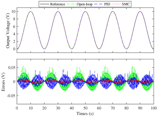
Figure 4.
The results of sinusoidal curve tracking with frequency of 0.05 Hz.

Figure 5.
The results of sinusoidal curve tracking with frequency of 0.1 Hz.
5.2. Resolution Ratio Test for Platform Rotational Movement
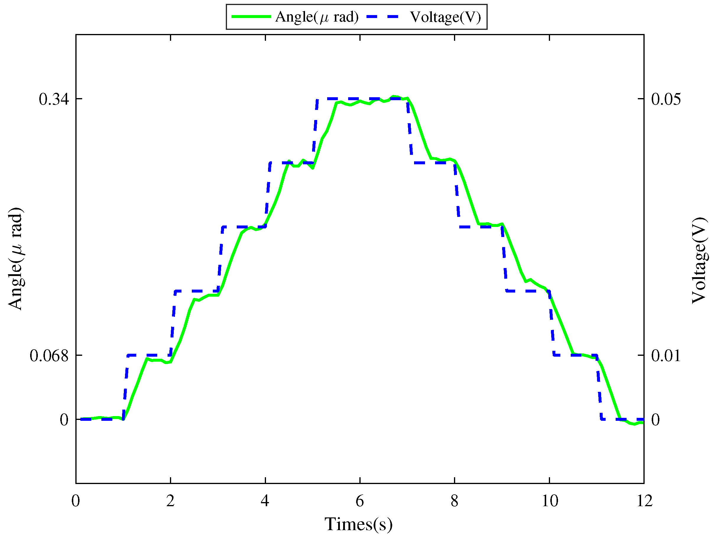
Figure 6 shows the resolution ratio test results. The curve of the broken line represents the input voltage for the sliding mode control scheme. This curve is characterized by five distinct rising and falling edges, each incrementing or decrementing by 0.01 V. The accompanying curve represents the deflection angle of the piezoelectric tip/tilt platform as measured by the laser interferometer. It is evident that an input voltage change of 0.01 V elicits an angular displacement of 0.068 μrad. Thus, the determined resolution ratio is 0.068 μrad.
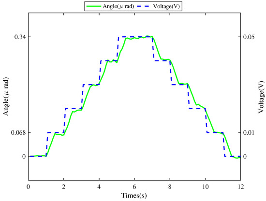
Figure 6.
Resolution ratio test results.
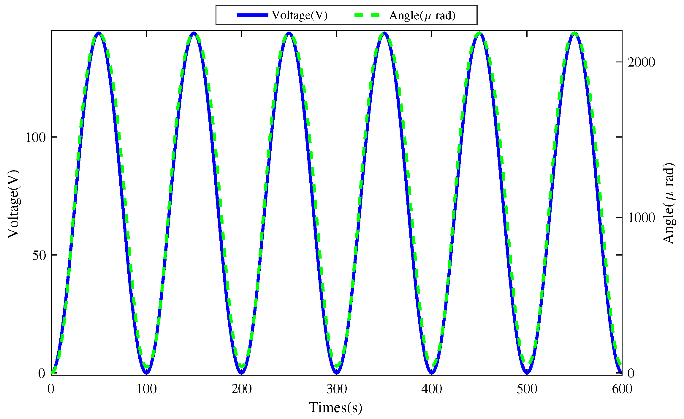
Figure 7 illustrates the calibration outcomes correlating the input voltage of the PZT actuator with the rotational angle of the tip/tilt platform. The depicted input voltage reaches its maximum value for the PZT actuator. Thus, the angle graph shows the full range of rotation for the tip/tilt platform, reaching a maximum angle of 2183 μrad. The voltage curve adheres to the formulation presented in Formula (14). Herein, the amplitude A is defined as 72 V, and the frequency f was set at 0.01 Hz.
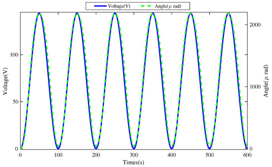
Figure 7.
Calibration results: angle and voltage.
The piezoelectric tip/tilt platform utilized in this study is analogous to the P562.6CD product offered by PI Corporation. Table 3 shows a comparison of the key parameters of P562.6CD and the piezoelectric tip/tilt platform. The P562.6CD boasts a closed loop resolution ratio of 0.1 μrad and can achieve a maximum deflection angle of 500 μrad. However, employing a sliding mode control strategy, our platform achieves an enhanced closed loop resolution ratio of 0.068 μrad, which is 68% of the P562.6CD even with five times the maximum deflection angle. Furthermore, a performance coefficient is introduced, representing the ratio of the resolution to the maximum angle. The coefficient for the piezoelectric tip/tilt platform is about 15.5% of the P562.6CD. Comparatively, the equipment employing the sliding mode control strategy demonstrates superior performance characteristics.
Table 3.
Comparison of performance parameters.
5.3. Discussion
The experimental results were quantified and analyzed by comparing the open-loop, PID, and sliding mode control schemes. The open-loop scheme’s results show the motion accuracy of the device system. PID is a closed-loop control. The performance deteriorates rapidly when subjected to external disturbances, and the control accuracy is not sufficiently high. This can result in significant motion tracking errors, potentially leading to tracking failure in severe cases. For the proposed sliding mode control scheme, the system moves in small increments along the sliding surface after reaching it. In this experiment, due to the structural characteristics of the piezoelectric tip/tilt platform, it is sensitive to external disturbances. The sliding mode control scheme is robust. And it is enough to limit the vibration of the flexure hinge so that smaller tracking errors and stable motion states can be gained.
Tracking error and robustness are the key issues to be considered in practical applications. In this experiment, the open-loop scheme produces micrometer-level vibrations in the presence of external disturbances. The PID system responds slowly to large external disturbances. When the model is disturbed, it also produces micrometer-level vibration. Therefore, for the new piezoelectric tip/tilt platform, considering the tracking error and robustness, the sliding mode control scheme is more suitable. Unavoidable modeling errors and disturbances are present in the experiments, and the robustness of the control scheme and tracking errors are verified by combining the experimental results mentioned above. The sliding mode control scheme proposed in this paper for the novel platform is a meaningful application, due to the strong robustness and small tracking error. However, the scheme also has some drawbacks:
- (1)
- The system’s high-frequency dynamics caused by the chattering effect.
- (2)
- A more accurate model for hysteresis has not yet been developed.
- (3)
- The need for more efficient methods for parameter identification.
Based on the above three problems, the proposed sliding mode control scheme can be improved in future research.
6. Conclusions
In this paper, the design of a sliding mode controller is proposed for a new piezoelectric tip/tilt platform and its application to precision motion tracking. This scheme effectively mitigates the hysteresis nonlinearity associated with the PZT actuator and addresses the inherent nonlinearity embedded within the platform’s design. Based on this platform, the tracking performance of the sliding mode control strategy is analyzed. In comparison with the traditional PID control scheme, the implemented sliding mode controller demonstrates enhanced robustness and reduced tracking errors. Compared with P562.6CD, the proposed approach achieves a superior resolution with a low cost. The significance of this research lies on the development of a novel control scheme tailored for the new platform, effectively addressing the challenges of nonlinearity and motion stability. This advancement ensures that the platform maintains its relatively high resolution and low cost. This sliding mode control scheme can be combined with another control strategy. And it can be applied to other similar device that need a higher motion accuracy.
Author Contributions
Conceptualization, X.Z. (Xianfeng Zeng) and X.Z. (Xiaozhi Zhang); methodology, X.Z. (Xianfeng Zeng) and X.Z. (Xiaozhi Zhang); software, X.Z. (Xianfeng Zeng); validation, X.Z. (Xianfeng Zeng) and X.Z. (Xiaozhi Zhang) and F.N.; formal analysis, X.Z. (Xianfeng Zeng); investigation, X.Z. (Xiaozhi Zhang); resources, X.Z. (Xiaozhi Zhang) and F.N.; data curation, X.Z. (Xianfeng Zeng); writing—original draft preparation, X.Z. (Xianfeng Zeng); writing—review and editing, X.Z. (Xianfeng Zeng) and X.Z. (Xiaozhi Zhang) and F.N.; supervision, F.N.; project administration, X.Z. (Xiaozhi Zhang). All authors have read and agreed to the published version of the manuscript.
Funding
This research received no external funding.
Data Availability Statement
The original contributions presented in the study are included in the article, further inquiries can be directed to the corresponding author.
Conflicts of Interest
The authors declare no conflicts of interest.
References
- Guo, D.; Nagel, W.S.; Clayton, G.M.; Leang, K.K. Spatial-Temporal Trajectory Redesign for Dual-Stage Nanopositioning Systems With Application in AFM. IEEE ASME Trans. Mechatron. 2020, 25, 558–569. [Google Scholar] [CrossRef]
- Habibullah, H. 30 Years of atomic force microscopy: Creep, hysteresis, cross-coupling, and vibration problems of piezoelectric tube scanners. Measurement 2020, 159, 107776. [Google Scholar] [CrossRef]
- Deng, J.; Liu, Y.; Chen, W.; Yu, H. A XY Transporting and Nanopositioning Piezoelectric Robot Operated by Leg Rowing Mechanism. IEEE ASME Trans. Mechatron. 2019, 24, 207–217. [Google Scholar] [CrossRef]
- Chang, Q.; Gao, X.; Liu, Y.; Deng, J.; Zhang, S.; Chen, W. Development of a cross-scale 6-DOF piezoelectric stage and its application in assisted puncture. Mech. Syst. Signal Process. 2022, 174, 109072. [Google Scholar] [CrossRef]
- Yu, S.; Xie, M.; Wu, H.; Ma, J.; Li, Y.; Gu, H. Composite proportional-integral sliding mode control with feedforward control for cell puncture mechanism with piezoelectric actuation. ISA Trans. 2022, 124, 427–435. [Google Scholar] [CrossRef]
- Liu, Y.T. Recent Development of Piezoelectric Fast Tool Servo (FTS) for Precision Machining. Int. J. Precis. Eng. Manuf. 2024, 25, 851–874. [Google Scholar] [CrossRef]
- Morita, T. Miniature piezoelectric motors. Sens. Actuators A Phys. 2003, 103, 291–300. [Google Scholar] [CrossRef]
- Delibas, B.; Koc, B. A method to realize low velocity movability and eliminate friction induced noise in piezoelectric ultrasonic motors. IEEE/ASME Trans. Mechatron. 2020, 25, 2677–2687. [Google Scholar] [CrossRef]
- Sabarianand, D.; Karthikeyan, P.; Muthuramalingam, T. A review on control strategies for compensation of hysteresis and creep on piezoelectric actuators based micro systems. Mech. Syst. Signal Process. 2020, 140, 106634. [Google Scholar] [CrossRef]
- Mohith, S.; Upadhya, A.R.; Navin, K.P.; Kulkarni, S.; Rao, M. Recent trends in piezoelectric actuators for precision motion and their applications: A review. Smart Mater. Struct. 2020, 30, 013002. [Google Scholar] [CrossRef]
- Kong, L.; Li, D.; Zou, J.; He, W. Neural Networks Based Learning Control for a Piezoelectric Nanopositioning System. IEEE ASME Trans. Mechatron. 2020, 25, 2904–2914. [Google Scholar] [CrossRef]
- Chen, Z.; Zhong, X.; Shi, J.; Zhang, X. Damping-enabling technologies for broadband control of piezo-stages: A survey. Annu. Rev. Control 2021, 52, 120–134. [Google Scholar] [CrossRef]
- Hazeleger, L.; Beerens, R.; van de Wouw, N. Proportional-Integral-Derivative-Based Learning Control for High-Accuracy Repetitive Positioning of Frictional Motion Systems. IEEE Trans. Control Syst. Technol. 2021, 29, 1652–1663. [Google Scholar] [CrossRef]
- Gambhire, S.; Kishore, D.R.; Londhe, P.; Pawar, S. Review of sliding mode based control techniques for control system applications. Int. J. Dyn. Control 2021, 9, 363–378. [Google Scholar] [CrossRef]
- Somefun, O.A.; Akingbade, K.; Dahunsi, F. The dilemma of PID tuning. Annu. Rev. Control 2021, 52, 65–74. [Google Scholar] [CrossRef]
- George, J.; Mani, G.; Alexander Stonier, A. An extensive critique of sliding mode control and adaptive neuro-fuzzy inference system for nonlinear system. Asian J. Control 2022, 24, 2548–2564. [Google Scholar] [CrossRef]
- Fei, J.; Feng, Z. Adaptive fuzzy super-twisting sliding mode control for microgyroscope. Complexity 2019, 2019, 6942642. [Google Scholar] [CrossRef]
- Ding, S.; Park, J.H.; Chen, C.C. Second-order sliding mode controller design with output constraint. Automatica 2020, 112, 108704. [Google Scholar] [CrossRef]
- Fei, J.; Wang, H.; Fang, Y. Novel Neural Network Fractional-Order Sliding-Mode Control With Application to Active Power Filter. IEEE Trans. Syst. Man Cybern.-Syst. 2022, 52, 3508–3518. [Google Scholar] [CrossRef]
- Mien, V.; Mavrovouniotis, M.; Ge, S.S. An Adaptive Backstepping Nonsingular Fast Terminal Sliding Mode Control for Robust Fault Tolerant Control of Robot Manipulators. IEEE Trans. Syst. Man Cybern. Syst. 2019, 49, 1448–1458. [Google Scholar] [CrossRef]
- Xu, B.; Zhang, L.; Ji, W. Improved Non-Singular Fast Terminal Sliding Mode Control With Disturbance Observer for PMSM Drives. IEEE Trans. Transp. Electrif. 2021, 7, 2753–2762. [Google Scholar] [CrossRef]
- Lee, S.D.; Phuc, B.D.H.; Xu, X.; You, S.S. Roll suppression of marine vessels using adaptive super-twisting sliding mode control synthesis. Ocean Eng. 2020, 195, 106724. [Google Scholar] [CrossRef]
- Lin, C.H.; Ho, C.W.; Hu, G.H.; Sreeramaneni, B.; Yan, J.J. Secure Data Transmission Based on Adaptive Chattering-Free Sliding Mode Synchronization of Unified Chaotic Systems. Mathematics 2021, 9, 2658. [Google Scholar] [CrossRef]
- Mobayen, S.; Vargas, A.N.; Acho, L.; Pujol-Vazquez, G.; Caruntu, C.F. Stabilization of two-dimensional nonlinear systems through barrier-function-based integral sliding-mode control: Application to a magnetic levitation system. Nonlinear Dyn. 2023, 111, 1343–1354. [Google Scholar] [CrossRef]
- Roohi, M.; Mirzajani, S.; Basse-O’Connor, A. A No-Chatter Single-Input Finite-Time PID Sliding Mode Control Technique for Stabilization of a Class of 4D Chaotic Fractional-Order Laser Systems. Mathematics 2023, 11, 4463. [Google Scholar] [CrossRef]
- Yin, X.; She, J.; Wu, M.; Sato, D.; Ohnishi, K. Disturbance rejection using SMC-based-equivalent-input-disturbance approach. Appl. Math. Comput. 2022, 418, 126839. [Google Scholar] [CrossRef]
- Du, Z.; Su, Y.; Yang, W.; Dong, W. Note: A piezo tip/tilt platform: Structure, kinematics, and experiments. Rev. Sci. Instrum. 2014, 85, 046102. [Google Scholar] [CrossRef] [PubMed]
- Han, W.; Shao, S.; Zhang, S.; Tian, Z.; Xu, M. Design and modeling of decoupled miniature fast steering mirror with ultrahigh precision. Mech. Syst. Signal Process. 2022, 167, 108521. [Google Scholar] [CrossRef]
- Zhang, S.; Liu, Y.; Deng, J.; Li, K.; Chang, Q. Development of a low capacitance two-axis piezoelectric tilting mirror used for optical assisted micromanipulation. Mech. Syst. Signal Process. 2021, 154, 107602. [Google Scholar] [CrossRef]
- Zhong, J.; Li, L.; Nishida, R.; Shinshi, T. Design and evaluation of a PEA-driven fast steering mirror with a permanent magnet preload force mechanism. Precis. Eng. J. Int. Soc. Precis. Eng. Nanotechnol. 2020, 62, 95–105. [Google Scholar] [CrossRef]
- Ling, J.; Feng, Z.; Zheng, D.; Yang, J.; Yu, H.; Xiao, X. Robust adaptive motion tracking of piezoelectric actuated stages using online neural-network-based sliding mode control. Mech. Syst. Signal Process. 2021, 150, 107235. [Google Scholar] [CrossRef]

Disclaimer/Publisher’s Note: The statements, opinions and data contained in all publications are solely those of the individual author(s) and contributor(s) and not of MDPI and/or the editor(s). MDPI and/or the editor(s) disclaim responsibility for any injury to people or property resulting from any ideas, methods, instructions or products referred to in the content. |
© 2024 by the authors. Licensee MDPI, Basel, Switzerland. This article is an open access article distributed under the terms and conditions of the Creative Commons Attribution (CC BY) license (https://creativecommons.org/licenses/by/4.0/).