Abstract
The series elastic actuator (SEA) is generally used as the torque source of the exoskeleton robot for human–robot interaction (HRI). In this paper, an impedance control method for lower limb exoskeleton robots driven by SEA is presented. First, considering the low-frequency vibrations generated by the lower limb exoskeleton robot during walking, the displacement generated by the robot is regarded as an external disturbance to the SEA motor. An SEA structure with negative stiffness structure (NSS) is designed to achieve vibration isolation in the low-frequency excitation region. Second, the dynamics model of the SEA-driven exoskeleton robot system is proposed, and the impedance control strategy is integrated into the proposed system. In addition, the numerical responses of the vibration-isolation system in both time and frequency domains are given, and the designed NSS is designed to achieve vibration isolation. The amplitude-frequency responses of the system are obtained. The harmonic balance (HB) method is used to give the analytical solution of the designed negative-stiffness isolation system, and the effects of different characteristic parameters on the isolation system are analyzed. Moreover, the stability of the SEA-driven exoskeleton impedance control system is demonstrated using the Lyapunov method. Finally, numerical simulations are carried out in order to show the effectiveness of the control method.
1. Introduction
Assistive robots are gaining attention and becoming human helpers in social environments [1,2,3,4], e.g., navigation robots, machine manipulators, and exoskeleton robots worn by hemiplegic patients, etc. An exoskeleton robotic system is an assistive robotic system with a humanoid structure that can be worn and assist the wearer to accomplish a corresponding task with the prediction of the intention of the wearer. In contrast to conventional robots, the motion system of exoskeletal robots needs to be consistent with the wearer, and therefore, effective HRI is essential. However, the lower limb exoskeleton robot is susceptible to factors such as conditions and external environment during walking; considering the impact from the ground causes body vibrations, in order to reduce the impact of low-frequency vibrations on the human body when the lower limb exoskeleton robot is walking, it is necessary to consider certain vibration-isolation designs in the control process.
Due to the effects of low-frequency vibrations on different mechanical systems, the necessary vibration-isolation design is required; however, active control tends to be costly and energy constrained. As a result, active control always involves higher costs and more implementation difficulties than passive systems, and passive vibration isolation has been widely developed [5,6,7,8,9,10,11,12,13,14,15,16,17,18,19,20]. In recent years, Fang et al. [11,12] explored systems of vibration control and energy harvesting models for satellites by integrating a nonlinear energy sink (NES) and a giant magnetostrictive material (GMM), and the complexification-averaging (CX-A) technique was employed. Lu et al. [13] investigated the enhancement of circular-ring vibration-isolation performance by shape memory alloy (SMA) wire ropes. The NSS exhibits much lower dynamic stiffness compared to static systems or mechanisms, which provides the opportunity to achieve the lowest possible filtering without compromising other characteristics. Furthermore, in recent years, Lu et al. [14,15,16,17] have proposed many novel vibration-isolation structures and applied them to different projects, including the design of a new two-stage nonlinear vibration-isolation system, each with high-static-low-dynamic stiffness (HSLDS), with the positive stiffness of each stage achieved by a metal plate, and the corresponding negative stiffness achieved by a bistable carbon-fiber-metal (CF) composite plate. An analytical model was used and the plate was statically tested to measure the actual stiffness of the plate. These studies have made great contributions in the field of nonlinear vibration isolation [21,22,23,24,25,26,27]. Le and Ahn [21] gave an NSS consisting of a pair of opposed springs perpendicular to the mass displacement, which generate a net vertical recovery force to achieve vibration isolation when there is a relative displacement between the floor and the seat. Phu et al. [25] introduced a hybrid magneto-rheological (MR) damper containing a combination of three control strategies controllers: PI control, fuzzy neural control, and sliding mode control. In [26], a method for estimating the natural frequencies of Cartesian 3D printers based on the kinematic scheme was introduced. Gholikord et al. [27] experimentally tested a novel design of negative-stiffness (NS) structure and improved the performance of the negative-stiffness structure in terms of energy absorption as well as maintaining its original configuration under cyclic loading. Compared with Gholikord et al., the new structure with NSS characteristics designed based on an exoskeleton structure not only expands the diversity of quasi-zero stiffness structures, but also shows excellent performance in the field of low-frequency vibration isolation.
A series of SEAs have been designed to drive the exoskeleton robot [28,29,30,31,32]. Kong et al. [28] proposed the control method of rotary SEA and a gait phase-smoothing sliding model-based control method was given for exoskeleton robots. In [29], a nonlinear SEA for an exoskeleton robot is given. Three springs are connected in series between a direct-current (DC) servo motor (equipped with a harmonic reducer) and the load, which are, in turn, connected in parallel with each other. Li et al. [31] proposed an iterative learning impedance controller for a rehabilitation robot driven by an SEA, where the control target is specified as the desired impedance model. Hsieh et al. [32] designed a unidirectional force-sensing SEA for shoulder rehabilitation, which uses a single linear compression spring connected in series between a linear stepper motor and a slider to generate a unidirectional linear output force by compressing the spring. Although different SEAs were designed in the above studies, the effect of the harmonic excitation on the SEA for exoskeleton robots was not considered.
In the case of HRI, it is possible to use force control as an alternative; however, its disadvantage is its poor robustness [33,34,35]. In contrast to force control, impedance control is a control strategy that controls the robot by regulating the dynamic relationship between the robot position and the interacting forces, and impedance control methods can improve the system stability. In recent years, impedance control has been further explored [36,37,38,39,40,41], and the studies have shown that impedance control has been effectively applied in robot control.
Inspired by the aforementioned discussions, this work has the following contributions: (1) This paper introduces a vibration-isolation design method for a lower limb exoskeleton robot using NSS under low-frequency harmonic excitation. The displacement generated by the robot is considered as an external disturbance to the motor. (2) The response of the NSS vibration-isolation system in the time and frequency domains is given by numerical solutions and HB methods. The effect of different characteristic parameters on the isolation system is analyzed by the analytical solutions. (3) The impedance control method is integrated into the dynamics model of the SEA-driven exoskeleton system and the stability of the overall system is demonstrated using the Lyapunov method.
2. Problem Formulation and Preliminaries
This section presents the SEA structure with NSS for a lower limb exoskeleton robot. In addition, the HRI force is given and will be viewed as an elastic external force.
2.1. SEA Structure with NSS
In the design of the NSS and exoskeleton, a simplified technical drawing is shown in Figure 1 that will help visualize the design.
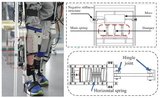
Figure 1.
A simplified technical drawing of the NSS and exoskeleton designs.
We took measurements to minimize backlash and ensure that saturation does not occur. For instance, we carefully selected actuators that have a high dynamic range and are not prone to saturation. Additionally, we used feedback control algorithms that can account for and compensate for nonlinearities in real-time. Regarding the issue of jamming, we took several precautions to ensure that the mechanism does not jam when the angle is large. We use rail guides to constrain the motion of the mechanism and prevent it from deviating from its intended path. We also use limiters to restrict the motion of the mechanism within safe operating ranges, and to prevent it from reaching extreme angles that could lead to jamming or other undesirable behaviors.
In order to achieve a compliance control of the exoskeleton robot, based on [31], a compliant actuator schematic is illustrated in Figure 2a; it is composed primarily of a servo motor with a rotary encoder, a set of linear and nonlinear springs, a ball screw and displacement sensors. The motion of the motor is first transmitted through a couple to the ball screw, and the couple transforms the rotational motion of the shaft into the linear motion of the ball screw nut. The motion of the nut is then passed through the NSS to the output carriage, which uses a pair of cables to drive the robot joints. An encoder is mounted on the motor to measure the angular displacement of the motor and ball screw, a displacement sensor is used to measure the displacement of the NSS, and a rotary potentiometer is mounted in the robot joint to measure the joint angle. Figure 2b shows the elastic element placed before the reducer, i.e., between the motor and the exoskeleton. The ball screws offer high precision and accuracy, which is crucial in many industries such as manufacturing, aerospace, and robotics. They have a low friction coefficient, which means they require less power to operate, and they are able to maintain their accuracy over long periods of use.
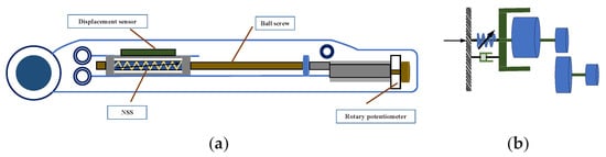
Figure 2.
Overview of the mechanical structure schematic of SEA: (a) Diagram of SEA structure with NSS. (b) Diagram of the placement of the elastic element.
The NSS is shown in Figure 3b. Here, the weight of the vibration isolation device is neglected. By means of a force F, opposite to the displacement, the mass is displaced downward x from its initial position and two horizontal springs are compressed and produce two vertical restoring forces acting on the mass. Figure 3a describes the HRI with vibration isolation structure.
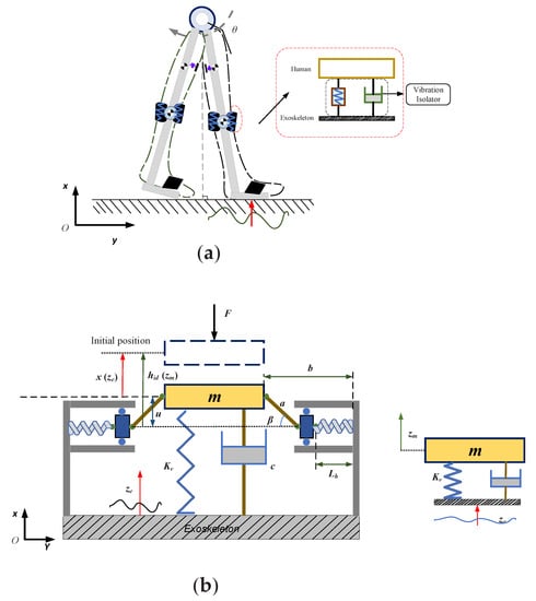
Figure 3.
Overview of the model structure schematics: (a) Diagram of vibration isolation structure with negative stiffness. (b) Schematic diagram of HRI with vibration-isolation structure.
The total virtual work of the vibration-isolated device on vertical direction is as
By applying the principle of virtual work, we can obtain
where is the horizontal spring force; is the angle of the horizontal line at the start; and are the lengths of the horizontal springs, respectively; and the length of the sliding block is neglected here.
At arbitrary positions, the angle can be established as
where
and
Substituting Equations (3)–(5) to the expression in Equation (2) for the horizontal spring force , it can be derived that
The following dimensional parameters can be defined as
where is the dimensionless restoring force, is the dimensionless displacement, and are configuration parameters, is the dimensionless deformation of the vertical spring, a is the length of the rod, and b is the distance from the edge to the edge.
Given these dimensionless parameters, the dimensionless restring force can be derived from Equation (6) as follows.
The above equation shows the parametric correlation between the dimensionless recovery force and the dimensionless displacement . Figure 4a,b describes the dimensionless force-deflection characteristics for various configuration parameters, and the configurative parameters of the NSS are shown in Table 1.
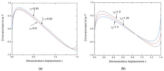
Figure 4.
Dimensionless force-deflection characteristics for various configuration parameters: (a) for various , (b) for various .

Table 1.
Configurative parameters of the NSS.
As for the range of values of NS, some predictions in the design of NSS can be derived from Figure 4. In this paper, as shown in Figure 4a, if the value of and , the maximum and minimum forces exist for the restoring force. The dimensionless restoring force decreases as the dimensionless mass displacement increases, while if the mass position is outside this range, the restoring force increases with the mass dimensionless displacement. This means that in this case, the structure has two different values of stiffness depending on the displacement of the mass. For example, , as shown in Figure 4a, if the displacement of the mass is in a region, the stiffness is positive and the other is negative. Similarly, the above analysis applies to Figure 4b.
2.2. Design Procedure of the Vibration Isolation System
When the mass is moved downward by x amounts from the initial position, as a result, the mass is compressed by three compressive forces including two restoring forces generated by the two horizontal springs and the force of the vertical spring. Thus, in this case, the vertical restoring force of the system can be obtained by adding the restoring force of the vertical spring on the left side of Equation (8).
The following dimensional parameters can be defined as
where denotes the spring ratio.
Define as the dimensionless displacement of the isolated device with respect to the base and Equation (9) can be rewritten as follows
The dimensionless dynamic stiffness of the system is obtained by differentiating Equation (10) with respect to the dimensionless displacement
When , the dimensionless equivalent stiffness at the static equilibrium position is described by
The above equation shows the parametric correlation between the dimensionless dynamic stiffness and the dimensionless displacement . The spring ratio is set as and . Figure 5 shows the dimensionless dynamic stiffness curves with linear stiffness for the various values of .
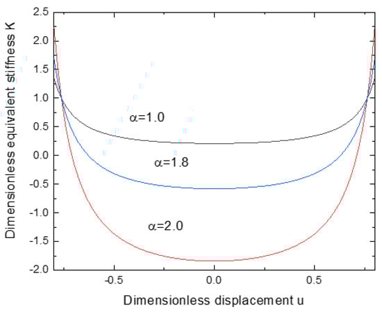
Figure 5.
Dynamic stiffnesscurves with linear stiffness for the various values of .
The resilience force for Equation (10) is expressed in the following dimensional form.
2.3. Human-Limb Model
Given the slow HRI process, based on [37], the human-limb model can be simplified as
where denotes the stiffness. is the desired position for a human limb.
When the system deviates from the initial position x, its potential energy V can be given as
The dissipation function is defined as
The kinetic energy T in the system is given by
Next, applying Lagrange’s equation,
where . P indicates the external excitation.
By substituting Equations (14)–(17) into Equation (18), the equation for the isolated control system can be derived as follows
The relative displacement, velocity and acceleration of the isolated control system are shown below
where , .
The dynamics system is rewritten as follows
2.4. Numerical Solution of Nonlinear Vibration Isolation System
Next, in order to analyze the dynamic response of the negative-stiffness isolation system, the numerical solution curves, time-amplitude response and frequency-amplitude response curves are given. The external excitation parameters are set to + cos (t), N, N/m. The results are shown in Figure 6a,b.
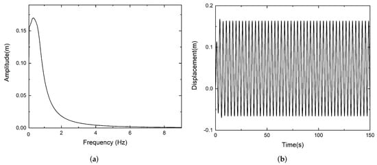
Figure 6.
Time and frequency amplitude response curves: (a) frequency and amplitude response curve, (b) time and amplitude response curve.
2.5. Harmonic-Balance Solution for Nonlinear Vibration-Isolation Systems
Considering the steady-state vibration around the static equilibrium position as well as the minimal displacement, at the static equilibrium position (), the extended power series of the restoring force can be approximated as
where denotes the approximate force and denotes the higher order term. Then, Equation (20) can be rewritten in terms of dimension, as below
Based on the Lagrange Equation (18), the approximate dynamic equation for the steady-state mass is derived below
where and . + cos (t), = cos (t).
The HB method is adopted and the solution is set as
Substituting the Equation (24) into (23), the following equations can be obtained based on HB method
Thus, the frequency and amplitude response relationship curves will be obtained based on (25) and (26). Different values of are set as , and , as shown in Figure 7a.
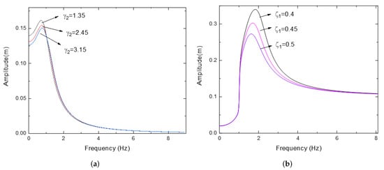
Figure 7.
Amplitude and frequency response curve for various (a) and (b) .
Next, different external excitations are considered, let cos (t), , = cos (t). Similarly, substituting the excitations into Equation (23), one can obtain
Then, the following equations can be obtained
Different values of are set as , and . The amplitude and frequency response curves can be obtained in Figure 7b.
3. Impedance Control of Integrated Robotic Systems
In this section, the dynamics model of the SEA-driven robot is proposed, impedance control is considered and a theorem is given for the control system of an exoskeleton robot.
3.1. Dynamic Model of SEA-Driven Robot
In this subsection, the dynamics model of the SEA-driven robot is presented in Cartesian space. Consider an exoskeleton robot connected by compliant joints, the schematic structure of the dynamics of the SEA-driven robot is shown in Figure 8.
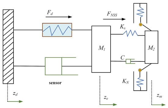
Figure 8.
Schematic diagram of the dynamics of the SEA-driven robot.
The dynamic model is described as follows
where is the symmetric inertia matrix and is the symmetric inertia matrix of actuator, and represent position vectors for HRI. represent position vector of actuator. denotes the input torque exerted on the actuator. denotes the interaction force between human and robot. denotes the force between robot and actuator and can be described by
where is the vector of Coriolis and centripetal forces, and are the stiffness vectors of SEA.
Considering the robot dynamics in Cartesian space by substituting the kinematic constraints (31) into the dynamic model (30), we obtain
and
Then, letting and represent the unknown nonlinear function, one has
and
Property 1
([37]). Matrices and are skew-symmetric matrices. Matrices and are symmetric and positive definite.
3.2. Impedance Control
Impedance control is integrated into the system; the robot is controlled to be compliant to the force applied by the human partner. The schematic diagram of impedance control is shown in Figure 9.
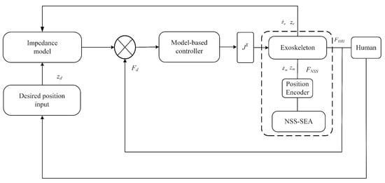
Figure 9.
Schematic diagram of impedance control.
Equivalently, the dynamics of the target impedance model is as follows [37],
where , and are the inertia, damping, and stiffness matrices that can be designed, respectively. is the desired position for the human–robot.
To achieve compliance control of the robot systems. The error signal should be constructed:
where is the error. There exist two positive definite matrices and such that
By substituting the above equations, one can obtain
Then, define
One can obtain
Assume that exists; will lead to . Therefore, we have if . Then, an augmented state variable is defined as
where is a reference vector. In order to propose the controller. First, (34) is rewritten as
where represents a fictitious desired input. Considering the variable Equation (42), the above equation can be rewritten as
Then, the desired input for the robot dynamics is proposed as
where is positive definite, is a positive constant, and is a sign function.
Next, a sliding vector is introduced for the actuator dynamics (35) as
where represents another reference vector, and is a positive constant, .
By considering the sliding vector, the actuator dynamics (35) can be rewritten as
Next, the control input is proposed as
where is a positive constant.
As a result, the impedance control model of the closed-loop system of the SEA-driven compliant robot is obtained, and in the next subsection, the system stability analysis will be performed.
3.3. Lyapunov Stability Analysis
Based on the above analysis, a block diagram of the control system of the closed-loop robot system was given. In addition, the following corollary is given in order to analyze the stability of the control system.
Corollary 1.
Considering the robot dynamics described in (30), the controller parameters and were chosen such that the condition (C1) is satisfied. The defined impedance error is guaranteed to converge asymptotically to 0 when , i.e., and all signals in the closed loop are bounded by designing the designed impedance control protocol.
Proof.
Consider the following Lyapunov function
According to Property 1, the time derivative of V is
By considering and as the upper bounds of and , respectively, the following inequalities hold
By choosing constants and , such that and , the above inequalities are less than or equal to 0.
Substituting into (52), we obtain
where and . Then, the controller parameters and are chosen such that
where and denote the minimum and the maximum eigenvalues.
If the chosen control parameters satisfy the condition (C1), then Q is non-negative definite and . This implies that V converges to a non-negative constant, since is bounded. Therefore, when , ; the impedance control objective is achieved. □
3.4. Simulation Results
Based on the above analysis, the dynamics model of the SEA-driven robot was proposed, and impedance control was integrated into the system. Moreover, numerical simulations were carried out in order to show the effectiveness of the control method proposed in this paper.
The desired trajectory for a human knee joint is specified as a sine wave, i.e., . The main parameters are chosen as , , , , , . The control input parameters are set as . By utilizing the proposed impedance control strategy, the simulation results are obtained. The desired gait trajectory is set as , and the position and velocity tracking trajectories are depicted in Figure 10; it can be seen that the desired position and velocity tracking trajectories can be tracked using the impedance control strategy. Thus, the given control strategy has good performance. The position and velocity trajectory of the SEA actuator is depicted in Figure 11. The interaction force variation curve is depicted in Figure 12, which shows that the interaction force tends to be compliant through the impedance control method.
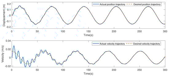
Figure 10.
The position and velocity trajectory of the robot.
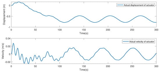
Figure 11.
The position and velocity trajectory of the SEA actuator.
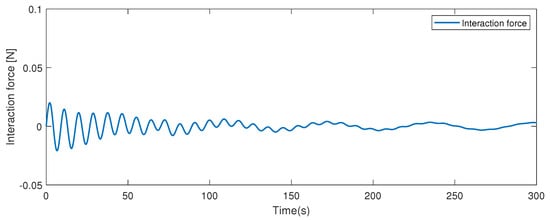
Figure 12.
The interaction force of the human–robot.
Next, through the method of parameter tuning, various parameters of the system are discussed by selecting different values so as to find the suitable range. Different values of and were tuned; the main parameters were chosen as , , . By utilizing the proposed impedance control strategy, the simulation results were obtained. The desired gait trajectory is set as , and the position and velocity tracking trajectories are depicted in Figure 13; it can be seen that desired position and velocity tracking trajectories can be tracked using the impedance control strategy. Thus, the given control strategy has good performance. The position and velocity trajectory of the SEA actuator is depicted in Figure 14. Set , ; similarly, through the proposed impedance control strategy, Figure 15 and Figure 16 are obtained. It can be seen that, compared with , , the tracking curve will oscillate when and increase or decrease in a certain range, and the oscillation is smaller when , .
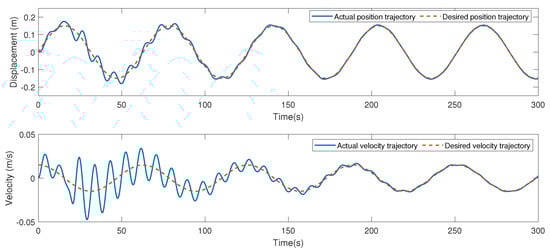
Figure 13.
The position and velocity trajectory of the robot.
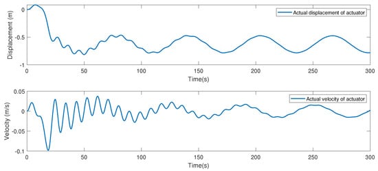
Figure 14.
The position and velocity trajectory of the SEA actuator.
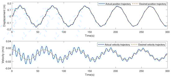
Figure 15.
The position and velocity trajectory of the robot.
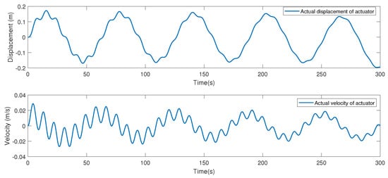
Figure 16.
The position and velocity trajectory of the SEA actuator.
Then, the desired trajectory is tuned. The desired trajectory for a human knee joint is specified as . The main parameters are chosen as , , , , , and . The results are depicted in Figure 17 and Figure 18. It can be seen that desired position and velocity tracking trajectories can be tracked.
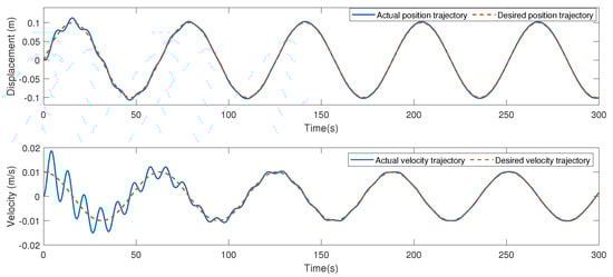
Figure 17.
The position and velocity trajectory of the robot.
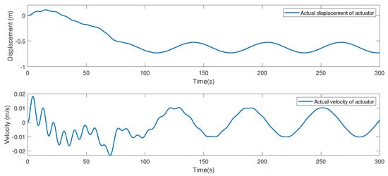
Figure 18.
The position and velocity trajectory of the SEA actuator.
4. Conclusions
In this paper, a novel impedance control method for lower limb exoskeleton robots driven by SEA was presented. An SEA structure with NSS was designed to achieve vibration isolation. The response of the NSS structure isolation system in the time and frequency domains was given numerically. In addition, the analytical solution of the designed negative stiffness-isolation system was given with the HB method and the effect of different characteristic parameters on the isolation system was analyzed. In addition, the impedance control method was given and the stability of the control system was demonstrated through the Lyapunov method. Finally, numerical simulations showed that the given control strategy has good performance.
Author Contributions
Writing—review and editing, Y.S.; project administration, J.H.; funding acquisition, R.H. All authors have read and agreed to the published version of the manuscript.
Funding
This research was funded by National Natural Science Foundation of China under grant number 62003073.
Data Availability Statement
The data used to support the findings of this study are available from the corresponding author upon request.
Conflicts of Interest
The authors declare no conflict of interest.
References
- Qiao, H.; Wang, M.; Su, J.; Jia, S.; Li, R. The concept of “attractive region in environment” and its application in high-precision tasks with low-precision systems. IEEE/ASME Trans. Mechatron. 2015, 20, 2311–2327. [Google Scholar] [CrossRef]
- Guo, Q.; Yin, J.M.; Yu, T.; Jiang, D. Coupled-disturbance-observer-based position tracking control for a cascade electrohydraulic system. ISA Trans. 2017, 68, 367–380. [Google Scholar] [CrossRef]
- Chen, M.; Shao, S.-Y.; Jiang, B. Adaptive neural control of uncertain nonlinear systems using disturbance observer. IEEE Trans. Cybern. 2017, 47, 3110–3123. [Google Scholar] [CrossRef] [PubMed]
- Yu, X.; He, W.; Li, Y.; Xue, C.; Li, J.; Zou, J.; Yang, C. Bayesian estimation of human impedance and motion intention for human-robot collaboration. IEEE Trans. Cybern. 2021, 51, 1822–1834. [Google Scholar] [CrossRef] [PubMed]
- Maciejewski, I.; Meyer, L.; Krzyzynski, T. Modelling and multi-criteria optimisation of passive seat suspension vibro-isolating properties. J. Sound Vib. 2009, 324, 520–538. [Google Scholar] [CrossRef]
- Abbas, W.; Emam, A.; Badran, S.; Shebl, M.; Abouelatta, O. Optimal seat suspension design for a half-car with driver model using genetic algorithm. Intell. Control Autom. 2013, 4, 199–205. [Google Scholar] [CrossRef]
- Corbridge, C.; Griffin, M.J. Vibration and comfort: Vertical and lateral motion in the range 0.5 to 5.0 Hz. Ergonomics 1986, 29, 249–272. [Google Scholar] [CrossRef]
- Palomares, E.; Nieto, A.J.; Morales, A.L.; Chicharro, J.M.; Pintado, P. Dynamic behaviour of pneumatic linear actuators. Mechatronics 2017, 45, 37–48. [Google Scholar] [CrossRef]
- Zhang, J.; Liu, X.; Xia, Y.; Zuo, Z.; Wang, Y. Disturbance observer-based integral sliding-mode control for systems with mismatched disturbances. IEEE Trans. Ind. Electron. 2016, 63, 7040–7048. [Google Scholar] [CrossRef]
- Manevitch, L.I. The Description of Localized Normal Modes in a Chain of Nonlinear Coupled Oscillators Using Complex Variables. Nonlinear Dyn. 2001, 25, 95–109. [Google Scholar] [CrossRef]
- Fang, Z.W.; Zhang, Y.W.; Li, X.; Ding, H.; Chen, L.Q. Integration of a nonlinear energy sink and a giant magnetostrictive energy harvester. J. Sound Vib. 2017, 319, 35–49. [Google Scholar] [CrossRef]
- Fang, Z.W.; Zhang, Y.W.; Li, X.; Ding, H.; Chen, L.Q. Complexification-averaging analysis on a giant magnetostrictive harvester integrated with a nonlinear energy sink. J. Vib. Acoust. 2017, 140, 021009. [Google Scholar] [CrossRef]
- Lu, Z.Q.; Gu, D.H.; Ding, H.; Lacarbonara, W.; Chen, L.Q. A ring vibration isolator enhanced by shape memory pseudoelasticity. Appl. Math. Model. 2021, 100, 1–15. [Google Scholar] [CrossRef]
- Lu, Z.Q.; Brennan, M.J.; Yang, T.J.; Li, X.; Liu, Z.G. An investigation of a two stage nonlinear vibration isolation system. J. Sound Vib. 2013, 332, 1456–1464. [Google Scholar] [CrossRef]
- Lu, Z.Q.; Gu, D.H.; Ding, H.; Lacarbonara, W.; Chen, L.Q. Nonlinear vibration isolation via a circular ring. Mech. Syst. Signal. Process. 2020, 136, 106490. [Google Scholar] [CrossRef]
- Lu, Z.Q.; Brennan, M.J.; Ding, H.; Chen, L.Q. High-static-low-dynamic-stiffness vibration isolation enhanced by damping nonlinearity. Sci. China Tech. Sci. 2019, 62, 1103–1110. [Google Scholar] [CrossRef]
- Lu, Z.Q.; Yang, T.J.; Brennan, M.J.; Liu, Z.G.; Chen, L.Q. Experimental Investigation of a Two-stage Nonlinear Vibration Isolation System with High-static-Low-Dynamic Stiffness. ASME J. Appl. Mech. 2017, 84, 021001. [Google Scholar] [CrossRef]
- Matsumoto, Y.; Griffin, M.J. Dynamic response of the standing human body exposed to vertical vibration: Influence of posture and vibration magnitude. J. Sound Vib. 1998, 212, 81–94. [Google Scholar] [CrossRef]
- Lee, C.M.; Goverdovskiy, V.N.; Temnikov, A.I. Design of springs with “negative” stiffness to improve vehicle driver isolation. J. Sound Vib. 2007, 32, 865–874. [Google Scholar] [CrossRef]
- Lee, C.M.; Goverdovskiy, V.N. A multi-stage high-speed railroad vibration isolation system with “negative” stiffness. J. Sound Vib. 2012, 331, 914–921. [Google Scholar] [CrossRef]
- Le, T.D.; Ahn, K.K. Experimental investigation of a vibration isolation system using negative stiffness structure. Int. J. Mech. Sci. 2013, 70, 99–112. [Google Scholar] [CrossRef]
- Sun, Y.H.; Zhang, Y.W.; Ding, H.; Chen, L.Q. Nonlinear energy sink for a flywheel system vibration reduction. J. Sound Vib. 2018, 429, 305–324. [Google Scholar] [CrossRef]
- Oyelade, A.O. Vibration isolation using a bar and an Euler beam as negative stiffness for vehicle seat comfort. Adv. Mech. Eng. 2019, 11, 1–10. [Google Scholar] [CrossRef]
- Tu, L.; Ning, D.; Sun, S.; Li, W.; Huang, H.; Dong, M.; Du, H. A novel negative stiffness magnetic spring design for vehicle seat suspension system. Mechatronics 2020, 68, 102370. [Google Scholar] [CrossRef]
- Phu, D.X.; Choi, S.M.; Choi, S.B. A new adaptive hybrid controller for vibration control of a vehicle seat suspension featuring MR damper. J. Vib. Control. 2017, 23, 3392–3413. [Google Scholar] [CrossRef]
- Kopets, E.; Karimov, A.; Scalera, L.; Butusov, D. Estimating Natural Frequencies of Cartesian 3D Printer Based on Kinematic Scheme. Appl. Sci. 2022, 12, 4514. [Google Scholar] [CrossRef]
- Gholikord, M.; Etemadi, E.; Imani, M.; Hosseinabadi, M.; Hu, H. Design and analysis of novel negative stifness structures with significant energy absorption. Thin Wall Struct. 2022, 181, 110137. [Google Scholar] [CrossRef]
- Kong, K.; Bae, J.; Tomizuka, M. Control of rotary series elastic actuator for ideal force-mode actuation in human–robot interaction applications. IEEE/ASME Trans. Mechatron. 2009, 14, 105–118. [Google Scholar] [CrossRef]
- Wang, M.; Sun, L.; Yin, W.; Dong, S.; Liu, J.-T. Series elastic actuator torque control approach for interaction application. Acta Autom. Sin. 2017, 43, 1319–1328. [Google Scholar]
- Li, Y.; Tee, K.P.; Chan, W.L.; Yan, R.; Chua, Y.; Limbu, D.K. Continuous role adaptation for human-robot shared control. IEEE Trans. Robot. 2015, 31, 672–681. [Google Scholar] [CrossRef]
- Li, X.; Liu, Y.H.; Yu, H. Iterative learning impedance control for rehabilitation robots driven by series elastic actuators. Automatica 2018, 90, 1–7. [Google Scholar] [CrossRef]
- Hsieh, H.C.; Chen, D.F.; Chien, L.; Lan, C.C. Design of a parallel actuated exoskeleton for adaptive and safe robotic shoulder rehabilitation. IEEE/ASME Trans. Mechatron. 2017, 22, 2034–2045. [Google Scholar] [CrossRef]
- Ju, Z.; Ouyang, G.; Wilamowska-Korsak, M.; Liu, H. Surface EMG based hand manipulation identification via nonlinear feature extraction and classification. IEEE Sens. J. 2013, 13, 3302–3311. [Google Scholar] [CrossRef]
- Noohi, E.; Žefran, M.; Patton, J.L. A model for human–human collaborative object manipulation and its application to human–robot interaction. IEEE Trans. Robot. 2016, 32, 880–896. [Google Scholar] [CrossRef]
- Li, Y.; Tee, K.P.; Yan, R.; Chan, W.L.; Wu, Y. A framework of human–robot coordination based on game theory and policy iteration. IEEE Trans. Robot. 2016, 32, 1408–1418. [Google Scholar] [CrossRef]
- Li, Z.; Kang, Y.; Xiao, Z.; Song, W. Human-robot coordination control of robotic exoskeletons by skill transfers. IEEE Trans. Ind. Electron. 2017, 64, 5171–5181. [Google Scholar] [CrossRef]
- Li, Y.; Ge, S.S. Human–Robot collaboration based on motion intention estimation. IEEE/ASME Trans. Mechatron. 2014, 19, 1007–1014. [Google Scholar] [CrossRef]
- Le, T.D.; Ahn, K.K. Active pneumatic isolator system using negative stiffness structure for a vehicle seat. J. Sound Vib. 2014, 333, 1245–1268. [Google Scholar]
- Le, T.D.; Ahn, K.K. A vibration isolation system in low frequency excitation region using negative stiffness structure for vehicle seat. J. Sound Vib. 2011, 330, 6311–6335. [Google Scholar] [CrossRef]
- Huang, R.; Cheng, H.; Guo, H.; Lin, X.; Zhang, J. Hierarchical learning control with physical human-exoskeleton interaction. Inf. Sci. 2018, 432, 584–595. [Google Scholar] [CrossRef]
- Huang, R.; Cheng, H.; Qiu, J.; Zhang, J. Learning physical human-robot interaction with coupled cooperative primitives for a lower exoskeleton. IEEE Trans. Autom. Sci. Eng. 2019, 16, 1566–1574. [Google Scholar] [CrossRef]
Disclaimer/Publisher’s Note: The statements, opinions and data contained in all publications are solely those of the individual author(s) and contributor(s) and not of MDPI and/or the editor(s). MDPI and/or the editor(s) disclaim responsibility for any injury to people or property resulting from any ideas, methods, instructions or products referred to in the content. |
© 2023 by the authors. Licensee MDPI, Basel, Switzerland. This article is an open access article distributed under the terms and conditions of the Creative Commons Attribution (CC BY) license (https://creativecommons.org/licenses/by/4.0/).