Article

Effect of the Magnetorheological Damper Dynamic Behaviour on the Rail Vehicle Comfort: Hardware-in-the-Loop Simulation

1
Institute of Machine and Industrial Design, Faculty of Mechanical Engineering, Brno University of Technology, Technicka 2, 616 69 Brno, Czech Republic
2
Department of Transport Means and Diagnostics, Faculty of Transport Engineering, University of Pardubice, Studentska 95, 532 10 Pardubice, Czech Republic
*
Author to whom correspondence should be addressed.
Actuators 2023, 12(2), 47; https://doi.org/10.3390/act12020047
Submission received: 19 December 2022 / Revised: 12 January 2023 / Accepted: 17 January 2023 / Published: 19 January 2023
(This article belongs to the Special Issue 10th Anniversary of Actuators)

Abstract

:
Many publications show that the ride comfort of a railway vehicle can be significantly improved using a semi-active damping control of the lateral secondary dampers. However, the control efficiency depends on the selection of the control algorithm and the damper dynamic behaviour, i.e., its force rise response time, force drop response time and force dynamic range. This paper examines the influence of these parameters of a magnetorheological (MR) damper on the efficiency of S/A control for several control algorithms. One new algorithm has been designed. Hardware-in-the-loop simulation with a real magnetorheological damper has been used to get close to reality. A key finding of this paper is that the highest efficiency of algorithms is not achieved with a minimal damper response time. Furthermore, the force drop response time has been more important than the force rise response time. The Acceleration Driven Damper Linear (ADD-L) algorithm achieves the highest efficiency. A reduction in vibration of 34% was achieved.

1. Introduction

Rail transport has recently become increasingly important around the world. One of the most important parameters of a railway vehicle is comfort (carbody vibration). The damping system is primarily responsible for carbody vibration mitigation. Today, commonly-used passive dampers have limits and can no longer solve new problems. The carbody vibration can be reduced using a semi-active or active system. The active system contains actuators instead of springs and dampers. The actuator can precisely create the force required to dampen the sprung mass. The significant disadvantages of active systems are the relative complexity, high cost, energy consumption and difficulties in implementing a fail-safe system [1,2]. An alternative to an active system is a semi-active system. The semi-active damper can change the damping characteristic using data from various sensors [3,4]. Using magnetorheological (MR) dampers for semi-active (S/A) control is advisable because MR dampers have very good transient behaviour [5]. One of the advantages of the MR damper is the possibility of fail-safe behaviour using a permanent magnet [6].
In the case of railway vehicles, several publications have verified the potential benefits of semi-active control of lateral secondary MR dampers in reducing carbody vibrations. Codeca et al. [7] tested the semi-actively controlled lateral secondary dampers and their effect on the carbody vibrations on a laboratory stand. The experimental stand was excited by a signal obtained from a real measurement on the track when running at high speed. A combination of Skyhook and Acceleration Driven Damping algorithms achieved the highest efficiency, reducing vibrations by 34%, compared to passive damping. Lau and Liao [8] examined the effect of S/A control of the lateral secondary dampers on ride comfort. The semi-active algorithm is simple and switches between Low and High damping states based on the magnitude of carbody lateral velocity. If the carbody velocity exceeds the critical speed, the damper switches to a High state. The simulations were performed on a complex railway vehicle dynamic model. The carbody lateral vibration was reduced by 39% compared to the passive damper. Shin et al. [9] dealt with the simulation and experimental verification of the secondary lateral damper semi-active control effect. A half-vehicle model with nine degrees of freedom was used for the simulation. For experimental validation, a 1:5 scale real simplified model was used. The Skyhook algorithm decreased vibration by 77% in the simulation compared to passive damping and 67% in the experiment. Hudha et al. [10] used two types of Skyhook algorithm: body-based and bogie-based for the lateral secondary MR dampers. The vehicle’s body lateral deviation, yawing, and rolling motion were evaluated in a dynamic model of 17 degrees of freedom. The algorithms worked well, both improving all three criteria.
Papers [11,12] show that damper force response time is essential for the performance of semi-actively controlled damping systems. The shorter the response time, the better the S/A control performance. Paper [13] shows that the time response is further dependent on the piston velocity, the magnitude of the electric current change, the stiffness of the damper mounting and the control electronics. The response time is negatively affected by the formation of eddy currents in the piston core, but this problem can be solved by using a suitable core shape [5,14]. Response time also depends on the dwell time of Fe particles in the active-magnetic zone and the concentration of Fe particles in the carrier fluid [13]. Papers [5,7] show that force response time differs for force rise and drop. The damper dynamic range (the ratio of the damping force in the activated and non-activated state) is also essential for the efficiency of the S/A control [15].
The MR dampers exhibit highly non-linear behaviour, which is very difficult to model properly. The MR damper models used in simulations are always simplified and often do not correspond to the force generated by real MR damper for given working conditions, degrading the results from simulations of semi-active suspension. To avoid the problem, many teams used the Hardware-in-the-loop method to evaluate the semi-active algorithms. Choi et al. [16] used HILS to design a semi-active control seat for a truck vehicle, and Lee et al. [17] used it to study the S/A control of a car suspension. Misselhorn et al. [18] successfully tested HILS usability in suspension design, comparing HILS with a virtual simulation on a single corner model and a simplified physical model of motorcycle suspension. Kwak et al. [19] used HILS to verify the benefit of the Skyhook algorithm for the lateral movement of the railway vehicle carbody. Oh et al. [20] studied the active control of tramcars independently rotating wheels in HILS. This approach enables to use of force generated directly by the real MR damper excited by the pulsator. The pulsator position in the time is controlled by the output of a virtual model running on a suitable platform.

Problem Formulation

It is known that force response time and dynamic range have an essential effect on the effectiveness of S/A control but the impact of this effect on different S/A algorithms has not been directly investigated. It is also known that the response time is different for the force rise and force drop when the electric current changes but in the case of simulation with the implemented response time of the damper, the response time is considered to be the same for both force rise and force drop. It is not known whether this simplification is permissible. It can be assumed the longer response time and the lower dynamic range lead to the lower effectiveness of the strategy used, but it is not known what maximum response time is acceptable for different algorithms.
The paper’s main aim is to investigate the effect of selected parameters of the MR damper on rail suspension performance in detail. The response time of damping force rise, damping force drop, and dynamic force range are studied separately. The hardware-in-the-loop simulation with a real MR damper will be used to accommodate several non-linearity in damper dynamics. Simulations are evaluated for several known S/A damper control algorithms and one newly-designed algorithm (Acceleration Driven Damper Linear).

2. Materials and Methods

2.1. Vehicle Model

A lateral motion model of a rail vehicle with two degrees of freedom has been developed. The model represents one wheelset, half of the bogie frame and a quarter of a carbody. The model layout can be seen in Figure 1, and the following equations describe the model:
m 2 y ¨ 2 = k 2   y 2 y 1 + F m r
m 1 y ¨ 1 = k 2   y 2 y 1 F m r k 1   y 1 y 0 c 1   y ˙ 1 y ˙ 0
where F m r is s force of MR damper and y 2 ,   y 1 and y 0 are lateral displacements of carbody, bogie frame and wheelset. Other model parameters are listed in Table 1. The model parameters are derived from a four-axle locomotive weighing 90 tons. The lateral damper used is reduced in scale. Therefore the parameters of the vehicle model are also reduced by a ratio of 1:5.
The model was excited by defined lateral wheelset motion y 0 , which was obtained from a simulation of a complex multi-body model of a railway vehicle (electric locomotive) running on a straight track with irregularities at 160 km/h, which is the speed limit on Czech railways. This complex model with 58 degrees of freedom was created in the multi-body simulation tool “SJKV” [21]. The track irregularities were generated using PSD of track irregularities in Europe according to ORE B 176. The wheelset-track coupled dynamic is neglected, for a more objective comparison of the results of S/A algorithms, so excitation y 0 is still the same for every case. Figure 2 shows the wheelset lateral displacement course and the FFT analysis of this course. The duration of the excitation signal was 10 s. The excitation magnitude was at the original scale, so even the scale of the damper stroke corresponds to reality.

2.2. Hardware-in-the-Loop Simulation

Mathematically describing the behaviour of a real damper is very difficult because it is necessary to include hysteresis (magnetic, hydraulic, etc.), temperature dependence, etc., in the model. For simplified models, it is difficult to say whether they neglect some essential property. Therefore, it is necessary to use HIL simulation to bring it closer to reality. This simulation allows the damper response time and the dynamic range effect on the S/A control to be investigated on a real MR damper without needing a real vehicle or physical model.
The damper is mounted in a hydraulic pulsator, controlled by a control system (dSpace RTI1104 in this case). A virtual railway vehicle model was built in Matlab/Simulink and transferred to the ControlDesk program, which controls the dSpace system. Based on the damper-measured force, the simulation calculates the virtual position of sprung and unsprung masses ( y 2 and y 1 ) in real time. The calculated control signal 1 (see Figure 3 left) with the damper stroke y 2 y 1 (see Figure 1) is sent to the hydraulic pulsator, which excites the MR damper. The control signal 2 with the desired current (see Figure 3 left) is also sent in real-time to the current controller, which excites the MR damper.
The current controller is a self-made device that works in analogue voltage input-analogue current output mode. The highest achievable current is I = 3 A. The rise time of the electric current from 0 to 2 A is 1 ms as a response to input signal step 0–2 V, and the drop time from 2 to 0 A is 0.5 ms as a response to step 2–0 V. The pulsator assembly has a built-in load gauge HBM U2AD1/2 that measures the current damping force. Load gauge deflection at maximal damper force is 7 μm, so gauge mechanical response time is possible to neglect. The signal from the load gauge is amplified by an analogue bridge amplifier with no delay. The damping force data are input for the virtual model. The HILS schema is shown in Figure 3 left, and the HILS assembly is in Figure 3 right. It showed that the response time of the pulsator was significantly shorter than the response time of the damper, so it did not cause any problems.

2.3. Magnetorheological Damper

This study used a real MR damper with a stroke of 160 mm and a maximum damping force of 2000 N (at the piston velocity of 0.3 m/s). In the piston, the MR damper has one coil with an electric resistance of R = 1.39 Ω. The coil inductance in the damper electric circuit with MR fluid is L = 50 mH. The magnetic circuit is made of Sintex SMC material to achieve a fast transient response. The damper is described in more detail in the paper [5].

2.3.1. F-v-I Map

The F-v-I (force-velocity-electric current) map expresses the dependence of the damper force on the actual piston velocity and the electric current in the coil. The measurement of the F-v-I map was performed on the hydraulic pulsator in the configuration described in Figure 3. However, in the case of the F-v-I map measurement, the device did not work in HILS mode (pulsator stroke generated based on vehicle model simulations), but the course of the damper stroke was fixedly specified. The logarithmic sweep with a constant amplitude of 20 mm was used as an excitation signal in the frequency range of 0.05–1.6 Hz. Therefore, the velocity was increasing during the test. The maximum velocity was 0.2 m/s. The load gauge HBM U2AD1/2 was used. The electric current was measured by current clamps Fluke i30s. Signals were recorded by dSpace. The F-v-I map was calculated from measured data choosing the points with zero acceleration (centre of the stroke).
The measured F-v curves are shown in Figure 4. The damper F-v curves are symmetrical for both tension and compression, whereas the graph shows only the positive F-v curves part. The damper dynamic force range at piston velocity 0.1 ms−1 is d r   = 7.6.

2.3.2. Response Time

The dynamic (transient) behaviour of the MR damper is usually assumed to be a first-order system, and the response time is usually defined as a time constant τ 63 [22,23,24]. The force in time can then be described by the equation:
F v , t = F 0 v + F 1 v F 0 v · 1 e t τ 63
where F 0 v is a force at t = 0 , and F 1 v is force corresponding to the desired force for the given velocity and current, v is piston velocity, t is the time from the change of the control signal, and τ 63 is the time constant.
The time constant τ 63 means the time required to reach 63.2% of the final steady-state force (see Figure 5). Similarly, the time constant for the force drop τ 36 expresses how long it takes for the force to drop back to 36.8% of the initial force. Response times for damper force rise τ 63 , and for damper force drop τ 63 on unit-step electric current rise and drop will be determined from measured data in this paper.
The measurement configuration was the same as described in the previous sections (Figure 3). The damper was tested without flexible silent blocks. The electric current was activated (to I = 2 A) and deactivated (to I = 0 A) when the damper was mid-stroke. The transient force response was measured for electric current change from 0 A to 2 A and from 2 A to 0 A, and for piston velocity of 0.1 m/s, approximately 70% of the highest piston velocity reached during simulations. The methodology is described in more detail in [25].
Damper force response time was measured at τ 63 = 1.8 ms for force rise and τ 36 = 1.1 ms for force drop (see Figure 5). Every response time value is an average of five measurements.

2.4. Semi-Active Control

For evaluation of the response time impact on different control strategies, this research used passive mode, three well-known semi-active algorithms: Skyhook, Skyhook linear, and Acceleration Driven Damper and one newly designed: Acceleration Driven Damper Linear.

2.4.1. Skyhook

Skyhook with two states (SH-2) is a commonly used algorithm for comfort improvement. It was designed by Karnopp [26]. The control rule for this algorithm is based on two input signals: the carbody lateral velocity and the relative lateral velocity between the carbody and the bogie frame. If the carbody velocity is higher than the relative velocity between the carbody and the bogie frame, the damper is in the high damping state. Mathematically:
F v = F m a x v , | y ˙ 2 y ˙ 2 y ˙ 1 0 F m i n v , | y ˙ 2 y ˙ 2 y ˙ 1 < 0
where F v is a required damping force, F m a x v is damping force at a current of I m a x , F m i n v is damping force at I m i n , y ˙ 2 is carbody lateral velocity, and y ˙ 1 is bogie frame lateral velocity.

2.4.2. Skyhook Linear

The Skyhook Linear (SH-L) is an improved version of the ON/OFF Skyhook, published by Sammier [27]. This algorithm changes the damping characteristics continuously. Initially, the algorithm is designed as follows:
F v =        F m i n v ,       y ˙ 2 y ˙ 2 y ˙ 1 0 s a t α · F m a x v · y ˙ 2 y ˙ 1 + 1 α · F m a x v ·   y ˙ 2 y ˙ 2 y ˙ 1 ,   y ˙ 2 y ˙ 2 y ˙ 1 > 0      
where F v is a required damping force, F m a x v is damping force at a current of I m a x , and F m i n v is damping force at I m i n , y ˙ 2 is carbody lateral velocity, y ˙ 1 is bogie frame lateral velocity, α ∈ [0,1] is tuning, and sat denotes that F c F m i n v ,     F m a x v .
The algorithm has the best performance for α = 0 . For a simpler algorithm application, the damping force in the equation has been replaced by an electric current. So, the final calculation of the current looks as follows:
I = s a t I m a x ·   y ˙ 2 y ˙ 2 y ˙ 1 ,     y ˙ 2 y ˙ 2 y ˙ 1 0   I m i n ,                           y ˙ 2 y ˙ 2 y ˙ 1 < 0
where I is a required electric current, I m a x is a maximal electric current, I m i n is a minimal electric current, y ˙ 2 is carbody lateral velocity, y ˙ 1 is bogie frame lateral velocity, and sat denotes that I I m i n v ,   I m a x v .
The damping force is not linearly dependent on the electric current but converting the damping force to electric current so that the force corresponds to the equation above would be unnecessarily demanding. Therefore, there is some bias in the algorithm from the original version, but the control strategy still works well.

2.4.3. Acceleration Driven Damper

Acceleration Driven Damper (ADD-2) was designed by Savaresi [28]. This algorithm works such as Skyhook but uses carbody acceleration instead of carbody velocity. So, its realisation is more accessible in practice. Mathematically:
F v = F m a x v , | y ¨ 2 y ˙ 2 y ˙ 1 0 F m i n v , | y ¨ 2 y ˙ 2 y ˙ 1 < 0
where F v is a required damping force, F m a x v is damping force at a current of I m a x , F m i n v is damping force at I m i n , y ¨ 2 is carbody lateral acceleration, y ˙ 2 is carbody lateral velocity and y ˙ 1 is bogie frame lateral velocity.
The algorithm has a problem with unwanted fast-switching behaviour. A rapid change in damping force when switching the state causes a change in the acceleration orientation, which again causes the state switch. Thus, the damper switches state very quickly at low piston velocity, reducing the damper’s life. Savaresi also encountered this phenomenon of the problem of the fast-switching behaviour of ADD, but he did not deal with it [29]. However, this problem could be eliminated by switching the damper state only if the carbody lateral acceleration is larger than y ¨ 2 > 0.2 ms−2. If y ¨ 2 < 0.2 ms−2, the damper remains in the state from the previous step, regardless of the result of the equation y ¨ 2 y ˙ 2 y ˙ 1 . This equation is solved only if y ¨ 2 > 0.2 ms−2. Eliminating unwanted chattering behaviour further improved the efficiency of the algorithm.

2.4.4. Acceleration Driven Damper Linear

This variant of the algorithm Acceleration Driven Damper is new. It has not been described in the literature yet. The ADD algorithm was modified to a linear form according to the Skyhook linear pattern:
I = s a t I m a x ·   y ˙ 2 y ˙ 2 y ˙ 1 ,   y ¨ 2 y ˙ 2 y ˙ 1 0   I m i n ,                   y ¨ 2 y ˙ 2 y ˙ 1 < 0
where I is a required electric current, I m a x is a maximal electric current, I m i n is a minimal electric current, y ¨ 2 is carbody lateral acceleration, y ˙ 2 is carbody lateral velocity, y ˙ 1 is bogie frame lateral velocity, and sat denotes that I I m i n v , I m a x v .
The new algorithm is called Acceleration Driven Damper Linear (ADD-L). This algorithm has the same problem with unwanted damping force oscillations as ADD-2. This problem has been solved similarly as in the previous case.

2.5. Plan of Experiments and Evaluation Method

The simulations of S/A control were performed in HIL mode (Section 2.2), where the damper stroke y 2 y 1 is obtained based on the vehicle model simulation (Figure 1). Four case studies will be reported: (1) the influence of force rise response time, (2) the influence of force drop response time, (3) the influence of force rise and drop response time together in real proportions, and (4) the influence of dynamic force range. The variables for sensitivity analysis are in Table 2.
In case 3 the real damper does not have the same long response time for force rise and drop. The ratio between the force rise response time and force drop response time is about 1.7.
The influence of the response time was monitored from the shortest possible response times, determined by the damper design ( τ 63 = 1.8 ms and τ 36 = 1.1 ms, see Section 2.3.2), to response times of 56 ms. The longer force response times, then 1.8 ms or 1.1 ms, were created using the current controller. The current rises (or drops) exponentially according to the equation:
I t = I 0 + I 1 I 0 · 1 e t τ
where I 0 is an electric current at t = 0 , I 1 is the desired current, t is the time from the step of the control signal, and τ is an artificial current response time that is adjusted as needed.
When response time was slowed down using the current ramp-up, its real value was measured by the methodology described in Section 2.3.2. The required dynamic force range (DR) was set by I m i n . It showed that S/A algorithms have the best performance when the maximal electric current is I m a x = 2 A, and passive damping has the best performance when the current is I = 0.5 A. Thus, these currents were used in HILS.
The lateral acceleration of the carbody testifies, above all, to ride comfort. The overall RMS of lateral acceleration in relevant track sections was used to evaluate the comfort of the railway vehicle in on-track tests. This evaluation is also used by the standard EN 14363 [30].

3. Results and Discussion

3.1. Response Time Effect

Figure 6 shows the dependence of carbody lateral acceleration overall RMS on the response time of damping force rise τ 63 (case 1). The dependency is the same for all four algorithms. With decreasing τ 63 , the vibrations decrease linearly to τ 63 = 15 ms. After that, no significant improvement was observed for shorter response times. However, with a shorter time response, noise appears. The noise is caused by a large force impact during damper state switching. Enormous force impact is caused by a rapid change in damping force when a very short response time is used. We assume these force impacts cause unwanted vibrations and thus degrade the results for very short response times. The ideal force rise and drop response times for each algorithm are shown in Table 3. In case 1, the force drop response time was set statically, ideal for each algorithm, according to Table 3.
Figure 7 shows the effect of force drop response time τ 36 on carbody lateral acceleration overall RMS (case 2). The response time trend on RMS for algorithm SH-2 decreases to τ 36 = 1.1 ms. In the case of SH-L, the vibrations decrease linearly up to 20 ms, similarly to τ 63 , and the lowest value is at τ 36 = 9.5 ms (Figure 7 left). The performance of the ADD-2 and ADD-L algorithms is the best, surprisingly, for a force drop response time around τ 36 = 46 ms, see Figure 7 right. The force rise response time τ 63 was set statically, ideal for each algorithm, according to Table 3.
For SH-2 and SH-L algorithms, the response time for the damping force drop is significantly more critical than for the damping force rise. It is caused by the input electric current being switched to I m a x = 2 A when the damper piston velocity v 2 v 1 is zero (when the force for activated and non-activated states is 0 N) and switched to I m i n = 0 A when the piston velocity and damping force are non-zero, see Figure 8 left. In Figure 8 right, it can be seen that the artificial long response time τ 36 makes the function of the ADD-2 algorithm similar to the SH-L algorithm function. This similarity explains the importance of a long force drop response time for good results from the ADD-2 and ADD-L algorithms.
The effect of the response time of real damper (including response time for rise and drop) was tested (case 3), see Figure 9. It can be seen that the long response time significantly degrades the efficiency of the SH-2 algorithm. Dependency is linear. The shorter the response time, the lower RMS. However, the algorithm SH-L exhibits a significant improvement in RMS up until a response time of 30 ms. After exceeding this value, the improvement is not observed. For ADD-2 and ADD-L algorithms, it would be ideal to use a damper with a response time of around τ 63 = 16 ms and the corresponding τ 36 = 9.5 ms. When using the SH-L, ADD-2, or ADD-L algorithm, it is possible to achieve a vibration reduction of about 22% even with a response time of τ 63 = 57 ms and the corresponding τ 36 = 33.5 ms. Strecker et al. [31] wrote that a successful semi-active control requires a short response time of at least 20 ms, but they used the SH-2 algorithm, a different dynamic system for simulating, and an obstacle crossing as an excitation method. In this case, excitation with a relatively low frequency (2 Hz) is used, and more advanced algorithms for S/A control are used, so semi-active control works well even with a relatively long response time. Obviously, reducing the damper response time τ 63 to less than 8 ms does not make sense for a lateral movement of rail vehicle carbody. Therefore, our MR damper for a railway vehicle with force rise response time of τ 63 = 7.8 ms [32] is fast enough.

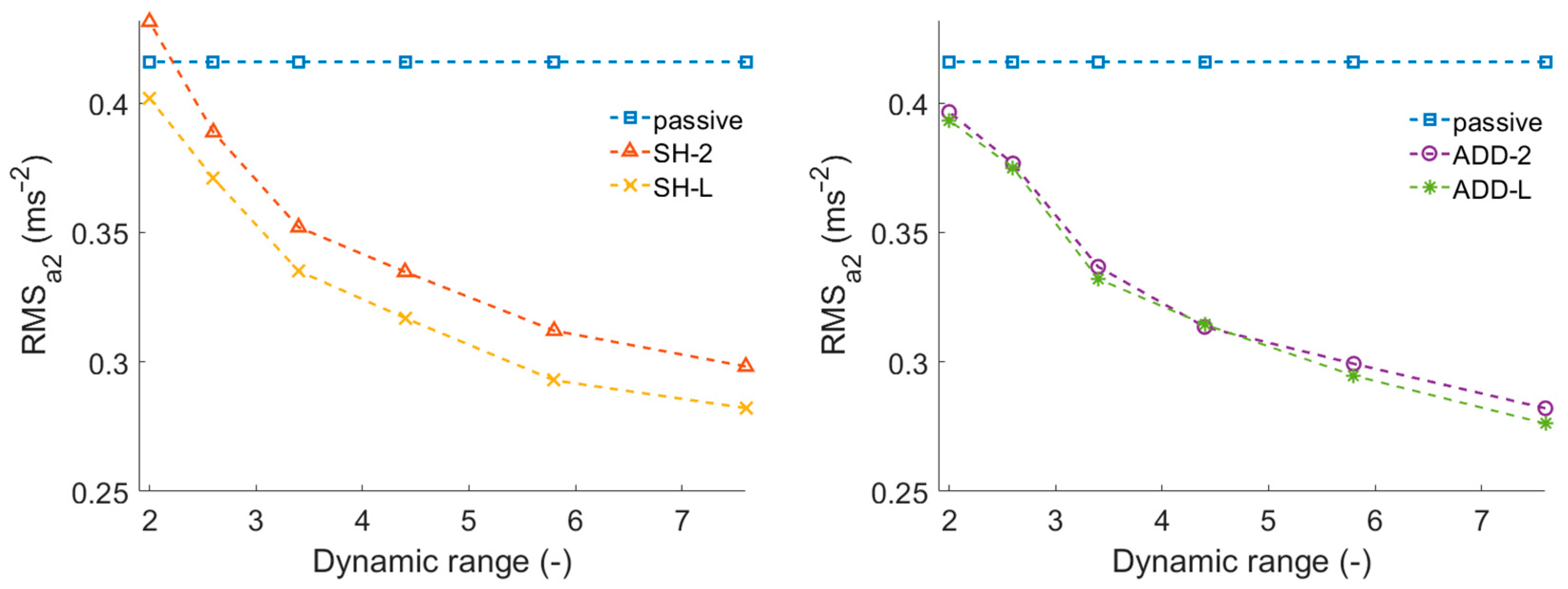
3.2. Dynamic Force Range Effect

Figure 10 shows the dependence of the S/A control efficiency on the force dynamic range of the damper (at piston velocity 0.1 ms−1). The vibration maximum RMS value increases with decreasing dynamic range for all algorithms. The Skyhook algorithm is more sensitive than other algorithms. It would be appropriate to change the damper design and make the dynamic range higher than 7.6 to achieve better results. It is possible to achieve a dynamic range of around 12 [33]. From the dependence course, it seems that the ideal value of the dynamic range could be around 10. The force rise and drop response times were set statically, ideal for each algorithm, according to Table 3. All cases of S/A control, except SH-2 with the dynamic range of 2, reduced carbody vibration.

3.3. Benefits of Each Algorithm

Table 4 shows the overall RMS of the lateral carbody vibrations determined by ideal response times. The most significant vibration reduction was performed by the ADD-L algorithm–33.6%. This value corresponds to the results of most previous research, e.g., [4,9].
In relation to this, SH-L achieved the same result as ADD-2, which was 32.2%. It is an important finding because ADD-2 is easier to apply to a real control system. Only an accelerometer for measuring the sprung mass acceleration and a displacement sensor for measuring the damper piston velocity are required for the ADD-2 application. When using the SH-2 or SH-L algorithm, it is necessary to integrate the sprung mass acceleration to obtain the sprung mass velocity, which leads to problems with the integration constant. The same problem must be solved for the ADD-L algorithm.
Courses of lateral acceleration of vehicle body in the time domain for selected results are shown in Figure 11.

4. Conclusions

The paper deals with the dynamic MR damper behaviour and its influence on the efficiency of four algorithms for semi-active control. A simple model of the lateral movement of a railway vehicle carbody with two degrees of freedom was used for the study. The Hardware-in-the-loop simulation was used. It has been confirmed that S/A control of dampers can significantly reduce carbody vibrations and increase crew comfort. For the selected dynamic system, the chosen excitation method and four selected control strategies, the key findings of this study can be summarised as follows:
  • Force drop response time is more important than force rise response time for S/A control performance.
  • In this dynamic system, there is no point in shortening the response time to less than τ63 = 8 ms.
  • The newly designed Acceleration Driven Damper Linear algorithm is best suited for damping the railway vehicle’s carbody lateral movement.
  • Under ideal conditions, vibrations were reduced by 34%.
  • Acceleration Driven Damper (two states) achieves the same effectiveness as Skyhook Linear, but Acceleration Driven Damper is easier to implement in real vehicles.
  • For better results, it would be appropriate to increase the dynamic range by at least 10.
In this research, the damper was mounted in the pulsator without silentblocks, which will probably not be possible in practice. However, the damper’s soft mounting will worsen the system’s hysteretic behaviour and reduce the effectiveness of the S/A control. Silentblocks of various stiffnesses are produced. It would be appropriate to investigate the dependence of the S/A control effectiveness on the damper mounting stiffness and determine what stiffness of the silentblock is acceptable for the S/A control. It will be part of follow-up research.

Author Contributions

Conceptualisation, F.J., M.K., Z.S.; methodology, F.J., Z.S.; software, F.J., T.M., J.Ž.; validation, F.J., J.Ž.; formal analysis, M.K., Z.S.; investigation, F.J., M.K., J.Ž.; data curation, F.J., T.M.; writing—original draft preparation, F.J., T.M.; writing—review and editing, F.J., M.K., T.M., Z.S., J.Ž., I.M.; visualisation, F.J., M.K.; supervision, M.K., Z.S., I.M.; project administration, M.K., I.M.; funding acquisition, M.K., I.M. All authors have read and agreed to the published version of the manuscript.

Funding

This work was supported partly by Czech Science Foundation under Grant GF21-45236L, partly by Technology Agency of the Czech Republic under Grant CK03000052 and party by Brno University of Technology under Grant FSI-S-20-6247.

Institutional Review Board Statement

Not applicable.

Informed Consent Statement

Not applicable.

Data Availability Statement

The data presented in this study are available on request from the corresponding author.

Conflicts of Interest

The authors declare no conflict of interest.

References

  1. Goodall, R.M. Control Engineering Challengs for Railway Trains of the Future. Meas. Control 2011, 44, 16–24. [Google Scholar] [CrossRef]
  2. Pérez, J.; Busturia, J.M.; Goodall, R.M. Control Strategies for Active Steering of Bogie-Based Railway Vehicles. Control Eng. Pract. 2002, 10, 1005–1012. [Google Scholar] [CrossRef]
  3. Shin, Y.J.; You, W.H.; Hur, H.M.; Park, J.H. Semi-Active Control to Reduce Carbody Vibration of Railway Vehicle by Using Scaled Roller Rig. J. Mech. Sci. Technol. 2012, 26, 3423–3431. [Google Scholar] [CrossRef]
  4. Codecà, F.; Savaresi, S.M.; Spelta, C.; Montiglio, M.; Ieluzzi, M. Semiactive Control of a Secondary Train Suspension. In Proceedings of the 2007 IEEE/ASME International Conference on Advanced Intelligent Mechatronics, Zurich, Switzerland, 4–7 September 2007. [Google Scholar] [CrossRef]
  5. Strecker, Z.; Jeniš, F.; Kubík, M.; Macháček, O.; Choi, S.B. Novel Approaches to the Design of an Ultra-Fast Magnetorheological Valve for Semi-Active Control. Materials 2021, 14, 2500. [Google Scholar] [CrossRef] [PubMed]
  6. Jeniš, F.; Kubík, M.; Macháček, O.; Šebesta, K.; Strecker, Z. Insight into the Response Time of Fail-Safe Magnetorheological Damper. Smart Mater. Struct. 2021, 30, 017004. [Google Scholar] [CrossRef]
  7. Spelta, C.; Savaresi, S.M.; Codecà, F.; Montiglio, M.; Ieluzzi, M. Smart-Bogie: Semi-Active Lateral Control of Railway Vehicles. Asian J. Control 2012, 14, 875–890. [Google Scholar] [CrossRef]
  8. Lau, Y.K.; Liao, W.H. Design and Analysis of Magnetorheological Dampers for Train Suspension. Proc. Inst. Mech. Eng. Part F J. Rail Rapid Transit 2005, 219, 261–276. [Google Scholar] [CrossRef]
  9. Shin, Y.-J.; You, W.-H.; Hur, H.-M.; Park, J.-H.; Lee, G.-S. Improvement of Ride Quality of Railway Vehicle by Semiactive Secondary Suspension System on Roller Rig Using Magnetorheological Damper. Adv. Mech. Eng. 2014, 6, 298382. [Google Scholar] [CrossRef] [Green Version]
  10. Hudha, K.; Harun, M.H.; Harun, M.H.; Jamaluddin, H. Lateral Suspension Control of Railway Vehicle Using Semi-Active Magnetorheological Damper. In Proceedings of the 2011 IEEE Intelligent Vehicles Symposium (IV), Baden-Baden, Germany, 5–9 June 2011; pp. 728–733. [Google Scholar] [CrossRef]
  11. Žáček, J.; Šebesta, K.; Mohammad, H.; Jeniš, F.; Strecker, Z.; Kubík, M. Experimental Evaluation of Modified Groundhook Car Suspension with Fast Magnetorheological Damper. Actuators 2022, 11, 354. [Google Scholar] [CrossRef]
  12. Jeyasenthil, R.; Yoon, D.S.; Choi, S.B. Response Time Effect of Magnetorheological Dampers in a Semi-Active Vehicle Suspension System: Performance Assessment with Quantitative Feedback Theory. Smart Mater. Struct. 2019, 28, 054001. [Google Scholar] [CrossRef]
  13. Koo, J.H.; Goncalves, F.D.; Ahmadian, M. A Comprehensive Analysis of the Response Time of MR Dampers. Smart Mater. Struct. 2006, 15, 351–358. [Google Scholar] [CrossRef]
  14. Yoon, D.S.; Park, Y.J.; Choi, S.B. An Eddy Current Effect on the Response Time of a Magnetorheological Damper: Analysis and Experimental Validation. Mech. Syst. Signal Process. 2019, 127, 136–158. [Google Scholar] [CrossRef]
  15. Macháček, O.; Kubík, M.; Strecker, Z.; Roupec, J.; Mazůrek, I. Design of a Frictionless Magnetorheological Damper with a High Dynamic Force Range. Adv. Mech. Eng. 2019, 11, 1687814019827440. [Google Scholar] [CrossRef] [Green Version]
  16. Choi, S.B.; Nam, M.H.; Lee, B.K. Vibration Control of a MR Seat Damper for Commercial Vehicles. J. Intell. Mater. Syst. Struct. 2001, 11, 936–944. [Google Scholar] [CrossRef]
  17. Lee, H.S.; Choi, S.B. Control and Response Characteristics of a Magneto-Rheological Fluid Damper for Passenger Vehicles. J. Intell. Mater. Syst. Struct. 2000, 11, 80–87. [Google Scholar] [CrossRef]
  18. Misselhorn, W.E.; Theron, N.J.; Els, P.S. Investigation of Hardware-in-the-Loop for Use in Suspension Development. Veh. Syst. Dyn. 2006, 44, 65–81. [Google Scholar] [CrossRef]
  19. Kwak, M.K.; Lee, J.H.; Yang, D.H.; You, W.H. Hardware-in-the-Loop Simulation Experiment for Semi-Active Vibration Control of Lateral Vibrations of Railway Vehicle by Magneto-Rheological Fluid Damper. Veh. Syst. Dyn. 2014, 52, 891–908. [Google Scholar] [CrossRef]
  20. Oh, Y.J.; Lee, J.K.; Liu, H.C.; Cho, S.; Lee, J.; Lee, H.J. Hardware-in-the-Loop Simulation for Active Control of Tramcars with Independently Rotating Wheels. IEEE Access 2019, 7, 71252–71261. [Google Scholar] [CrossRef]
  21. Zelenka, J.; Michalek, T.; Kohout, M. Comparative Simulations of Guiding Behaviour of an Electric Locomotive. In Proceedings of the 20th International Conference Engineering Mechanics 2014, Svratka, Czech Republic, 12–15 May 2014; pp. 740–743. [Google Scholar]
  22. Goncalves, F.D.; Koo, J.H.; Ahmadian, M. Experimental Approach for Finding the Response Time of Mr Dampers for Vehicle Applications. In Proceedings of the ASME Design Engineering Technical Conference; ASME: New York, NY, USA, 2003; Volume 5 A, pp. 425–430. [Google Scholar]
  23. Guan, X.; Guo, P.; Ou, J. Study of the Response Time of MR Dampers. In Proceedings of the Second International Conference on Smart Materials and Nanotechnology in Engineering, Weihai, China, 8–11 July 2009; Volume 7493, p. 74930U. [Google Scholar] [CrossRef]
  24. Koo, J.-H.; Goncalves, F.D.; Ahmadian, M. Investigation of the Response Time of Magnetorheological Fluid Dampers. In Smart Structures and Materials 2004: Damping and Isolation; SPIE: Bellingham, WA, USA, 2004; Volume 5386, p. 63. [Google Scholar] [CrossRef]
  25. Strecker, Z.; Roupec, J.; Mazurek, I.; Machacek, O.; Kubik, M.; Klapka, M. Design of Magnetorheological Damper with Short Time Response. J. Intell. Mater. Syst. Struct. 2015, 26, 1951–1958. [Google Scholar] [CrossRef]
  26. Karnopp, D.; Crosby, M.J.; Harwood, R.A. Vibration Control Using Semi-Active Force Generators. J. Eng. Ind. 1974, 96, 619. [Google Scholar] [CrossRef] [Green Version]
  27. Sammier, D.; Sename, O.; Dugard, L. Skyhook and H∞ Control of Semi-Active Suspensions: Some Practical Aspects. Veh. Syst. Dyn. 2003, 39, 279–308. [Google Scholar] [CrossRef]
  28. Savaresi, S.M.; Silani, E.; Bittanti, S. Acceleration-Driven-Damper (ADD): An Optimal Control Algorithm for Comfort-Oriented Semiactive Suspensions. J. Dyn. Syst. Meas. Control. Trans. ASME 2005, 127, 218–229. [Google Scholar] [CrossRef]
  29. Savaresi, S.M.; Spelta, C. Mixed Sky-Hook and ADD: Approaching the Filtering Limits of a Semi-Active Suspension. J. Dyn. Syst. Meas. Control. Trans. ASME 2007, 129, 382–392. [Google Scholar] [CrossRef]
  30. EN 14363:2016+A1; Railway Applications—Testing and Simulation for the Acceptance of Running Characteristics of Railway Vehicles—Running Behaviour and Stationary Tests. CEN (European Committee for Standardization): Brusel, Belgium, 2020.
  31. Strecker, Z.; Mazůrek, I.; Roupec, J.; Klapka, M. Influence of MR Damper Response Time on Semiactive Suspension Control Efficiency. Meccanica 2015, 50, 1949–1959. [Google Scholar] [CrossRef]
  32. Kubík, M.; Strecker, Z.; Jeniš, F.; Macháček, O.; Přikryl, M.; Špalek, P. Magnetorheological Yaw Damper with Short Response Time for Rail- Way Vehicle Bogie. In Proceedings of the International Conference and Exhibition on New Actuator Systems and Applications 2021, Online, 17–19 February 2021; Volume 36, pp. 373–376. [Google Scholar]
  33. Yang, G.; Spencer, B.F.; Carlson, J.D.; Sain, M.K. Large-Scale MR Fluid Dampers: Modeling and Dynamic Performance Considerations. Eng. Struct. 2002, 24, 309–323. [Google Scholar] [CrossRef]
Figure 1. Railway vehicle simplified model schema.
Actuators 12 00047 g001
Figure 2. Excitation signal y 0 (left) and its FFT analysis (right).
Actuators 12 00047 g002
Figure 3. Experimental setup for HILS (left), HILS assembly (right).
Actuators 12 00047 g003
Figure 4. Measured F-v-I map of the used damper.
Actuators 12 00047 g004
Figure 5. Example of measured response time for rise (left) and drop (right). I (A) is the measured electric current, and F (N) is the measured damping force.
Actuators 12 00047 g005
Figure 6. Damper force rise response time τ 63 effect for passive mode, SH-2 and SH-L algorithms (left) and passive mode, ADD-2 and ADD-L algorithms (right), HILS results.
Actuators 12 00047 g006
Figure 7. Damper force drop response time τ 36 effect for passive mode, SH-2 and SH-L algorithms (left) and passive mode, ADD-2 and ADD-L algorithms (right), HILS results.
Actuators 12 00047 g007
Figure 8. Course of v 2 –carbody lateral velocity from the model, v 2 v 1 damper piston velocity from the model,   I   –measured electric current in damper, F c –measured damper force, for SH-L control (left) and ADD-2 control (right), HILS results.
Actuators 12 00047 g008
Figure 9. Damper force drop response time τ 63 effect for passive mode, SH-2 and SH-L algorithms (left) and passive mode, ADD-2 and ADD-L algorithms (right), HILS results.
Actuators 12 00047 g009
Figure 10. Damper dynamic range DR effect for passive mode, SH-2 and SH-L algorithms (left) and for passive mode, ADD-2 and ADD-L algorithms (right), HILS results.
Actuators 12 00047 g010
Figure 11. Courses of lateral body acceleration in the time domain for passive mode, SH-L control (left) and ADD-L control (right), HILS results.
Actuators 12 00047 g011
Table 1. Model parameters.
ParameterSymbolOriginal1:5 Scale
half bogie frame weightm15000 kg1000 kg
quarter carbody weightm213,750 kg2750 kg
wheelset-bogie frame bond stiffnessk110 kN/mm2 kN/mm
bogie frame-carbody bond stiffnessk21 kN/mm0.2 kN/mm
wheelset-bogie frame bond dampingc110 kNs/m2 kNs/m
Table 2. The variables for sensitivity analysis.
Case τ 63   ( ms ) τ 36   ( ms ) DR at 0.1 m/s (-)
11.8–56*7.6
2*1.1–567.6
31.8–56 τ 63 /1.77.6
4**2–7.6
* Ideal response time for the selected algorithm.
Table 3. Ideal response times for selected algorithm.
Algorithm τ 63   ( ms )   τ 36   ( ms )
SH-27.91.1
SH-L109.5
ADD-212.846
ADD-L3.846
Table 4. Carbody lateral acceleration RMS (ms−2) for each mode and percentage reduction compared to passive mode.
ModeRMS (ms−2)Improvement (%)
passive0.4160
SH-20.29828.3
SH-L0.28232.2
ADD-20.28232.2
ADD-L0.27633.6
Disclaimer/Publisher’s Note: The statements, opinions and data contained in all publications are solely those of the individual author(s) and contributor(s) and not of MDPI and/or the editor(s). MDPI and/or the editor(s) disclaim responsibility for any injury to people or property resulting from any ideas, methods, instructions or products referred to in the content.

