Abstract
This paper presents the results of a comprehensive study of the pull-in phenomenon in the hybrid levitation microactuator (HLMA), in which square-shaped proof masses (PMs) of different sizes, namely, length sides of 2.8 and 3.2 mm and thicknesses of 25 and 10 μm were electromagnetically levitated. The pull-in actuation of the square-shaped PMs was performed by the electrostatic force generated by the set of energized electrodes and acting on the bottom surface of the PMs along the vertical direction. The pull-in parameters, such as pull-in displacements and the corresponding applied pull-in voltages, were measured with the developed setup. The experimental measurements showed that the pull-in actuation is nonlinearly dependent on the size and mass of the PMs and a levitation height. In particular, it was found that PMs levitated within a height range from 140 to 170 μm can be stably displaced within a range of 30 μm. The results of measurements were extensively simulated with the developed analytical model by means of the quasi-FEM method. The direct comparison of the results of simulation and measurements showed a very good agreement between the theory and experiments.
1. Introduction
Employing electromagnetic levitation in microactuator systems eliminates mechanical attachments in their moving parts and, consequently, mechanical friction and wear in these systems, which are further referenced as levitation microactuators (LMAs). In fact, the control of the friction and flexibility in the motion from remote actuation provided by electromagnetic levitation at the microscale has already found wide applications in microsystem devices and, in particular, led to the creation of a new generation of microactuators with increased operational capabilities and performance [1].
Electromagnetic levitation in LMA is implemented through sources of electric and magnetic force fields and their combination. According to the sources of the force fields, LMAs can be classified as electric levitation (ELMA), magnetic levitation (MLMA), and hybrid levitation (HLMA) microactuators. In particular, ELMAs were successfully used as linear transporters [2] and in microinertial sensors [3,4,5]. MLAMs can be further split into inductive (ILMA), diamagnetic (DLMA), and superconducting microactuators, which have found applications in microbearings [6,7,8], micromirrors [9], microgyroscopes [10,11], microaccelerometers [12], bistable switches [13], nanoforce sensors [14], inclination sensors [15], gas flow meters [16], microrobots [17], energy harvesters [18] and ultra-high-Q resonators [19].
Combining different force fields in one LMA, for instance, magneto- and electro-static, variable magnetic and electro-static, or magneto-static and variable magnetic fields, is an HLMA. HLMAs have found applications, for instance, in micromotors [20,21], micromirrors [22], and microaccelerators [23]. A wide range of different operation modes, such as linear and angular positioning, bistable linear and angular actuations, and the adjustment of stiffness components of a levitated microdisc, were developed and experimentally studied in a prototype of an HLMA [24]. In this prototype, the stiffness components were adjusted by changing the equilibrium position of the inductively levitated disc along the vertical axis. Recently, an HLMA was presented in which the electrostatic forces acting on the bottom and top surfaces of the inductively levitated microdisc maintained their equilibrium position while the vertical component of stiffness was decreased by means of increasing the strength of electrostatic field [25,26]. Thus, HLMAs are a very promising direction for further improvement in the performance of microsystem actuators.
In general, analytical and numerical analysis of LMAs for their further development and for proposing new designs for advanced applications requires applying the Maxwell equations. Although field equations are universally applicable, their application even for simple designs is a difficult task [27]. Even though these designs have been numerically studied by using commercially available software [28,29,30,31], this task is still a challenge, as not all aspects of LMA behavior, including the stability and linear and nonlinear dynamical response, cannot be covered.
Fortunately, LMA can be analyzed by using a certain analogy [32]. Upon holding the condition of quasi-stationarity for the force field ([33], page 493), the electromagnetic part of an LMA can be approximated by an equivalent circuit consisting of a set of lumped components, such as inductance, resistance, and capacitance. Considering a levitated object in LMA as rigid, the methods of analytical mechanics based on Lagrangian formalism become applicable. In particular, Okress et al. proposed replacing a levitated sphere by an alternating magnetic dipole [34]. Using this analogy, which can be known as one electric current circuit approximation (one-CCA), the levitating force acting on the sphere was studied. The same analogy was successfully applied to study the stability and dynamics in a number of different designs of a micromachined inductive contactless suspension, in which disc- and ring-shaped proof masses were levitated [7,35,36,37,38]. Moreover, the one-CCA analogy was used to examine the pull-in phenomenon in an HLMA, in which a levitated disc-shaped PM was actuated by the set of electrodes with a flouting electric ground [26,39,40].
The analogy of one-CCA was further generalized and extended to the approximation of the induced eddy current within a levitated proof mass by n number of electric current circuits [41]. This analogy is known as the n electric current circuit approximation (n-CCA). It helps to establish the necessary and sufficient conditions for stable levitation of an electromagnetic contactless suspension and, in particular, to provide general guidelines for designing LMAs. Due to the recent progress in the calculations of mutual inductance between filament loops [42,43,44], forces [45,46], and magnetic stiffness [47] between current-carrying filaments, the simulation approach for LMAs based on quasi-FEM was formulated [48]. In the formulated quasi-FEM method, the calculation of the induced eddy current within PMs is performed by means of the n-CCA analogy, but an each current circuit has a circular shape [49]. This makes this calculation applicable for any shape of a levitated PM and a coil wire carrying an excitation A/C current generating the force field. In particular, this method was successfully applied to simulate the pull-in actuation of a disc-shaped PM in an HLMA [48].
This paper presents the results of the comprehensive study of the pull-in phenomenon in an HLMA, in which square-shaped PMs of different sizes, namely, length sides of and and thicknesses of 25 and 10 μm, were electromagnetically levitated. The pull-in actuation of the square-shaped PMs was performed by the electrostatic force generated by the set of energized electrodes and acting on the bottom surface of the PMs along the vertical direction. The pull-in parameters, such as pull-in displacements and the corresponding applied pull-in voltages, were measured by means of the developed setup. The experimental measurements showed that the pull-in actuation is nonlinearly dependent on the size and mass of the PM and the levitation height. In particular, it was found that PMs levitated within a height range of 140 to 170 μm can be stably displaced within a range of 30 μm. The results of measurements were extensively simulated with the developed analytical model by means of the quasi-FEM method based on the n-CCA analogy. The direct comparison of the results of simulation and measurements showed a very good agreement between the theory and experimental results. Note that this study is an extended version of our results presented at the ACTUATOR 2022 conference and published in the conference proceedings [50].
2. Hybrid Levitation Microactuators
The prototype of an HLMA levitating a square-shaped proof mass with a side length of and at a height of 70 μm is shown in Figure 1A. The device consists of two independently fabricated structures: the two-coil structure and electrode structure, which were aligned and assembled by flip-chip bonding into one device with the dimensions of 9.4 × 7.4 × 1.1 mm, as shown in Figure 1A [24,51].
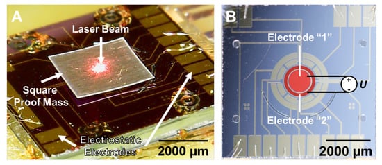
Figure 1.
(A) HLMA levitating square-shaped proof mass with a 2.8 mm side length and at a height of 70 μm. (B) The set of electrodes fabricated on the surface of the device layer of SOI wafer: the energized electrodes by the applied voltage U to carry out the pull-in actuation of the levitated PM are highlighted in red.
The coil structure included two coaxial 3D wire-bonded microcoils, similar to those reported in our previous study [7]: the stabilization and levitation coil have radii of and , respectively, which were fabricated on Pyrex substrate using SU-8 2150. The function of this structure is to stably levitate an aluminum (Al) square-shaped PM. For this particular device, the height of the coils was 500 μm, with 20 and 12 windings for the levitation and stabilization coil, respectively. This coil structure is able to levitate PMs with a side-length ranging from 2.7 to 3.3 .
The electrode structure was fabricated on an SOI wafer having a device layer of 40 μm, a buried oxide of 2 μm, a handle layer of 600 μm, and silicon resistivity in the range of 1.30 , as was reported in our study [26]. Additionally, the device layer had a 500 nm oxide layer for passivation, on the top of which electrodes were patterned by UV lithography on evaporated Cr/Au layers (20/150 nm). The fabricated electrode set, which is hidden by the levitated PM in Figure 1A, is shown in Figure 1B. After etching the handle layer up to the buried oxide by DRIE, the electrode structure was aligned and bonded onto the coil structure. Finally, the fabricated device was glued and wire-bonded on a PCB board.
In order to carry out the pull-in actuation of the levitated PM, electrodes “1” and “2”, which had the same area, , of m as shown in Figure 1B, were energized so that the squared PM was moved toward the electrode surface. The corresponding electrostatic force F could be estimated by the well-known formula,
where is the vacuum permittivity ( F/m), is the relative permittivity (for air ), U is the applied voltage, and h is the levitation height.
3. Experimental Setup and Measurements
In order to measure the pull-in parameters of the prototype, the experimental setup was developed. A schematic of the setup is shown in Figure 2. The PCB board with the device was mounted on an optical table, as shown in Figure 2. The device coils were fed by the square-wave A/C current provided by the control circuit developed by our group. It had dimensions of and consisted of a generator based on high-speed flip-flop components and a current amplifier built on an H-bridge configuration. The circuit was able to generate an A/C current with a squared waveform in a frequency range of 8 to 43 and with a peak-to-peak amplitude of up to 420 [49]. An electrically conductive proof mass was levitated by excitation of the nested 3D microcoils with the A/C current. Electrically conductive Al films were used for PMs, and they were cut with an Acsys Piranha II (ACSYS Lasertechnik GmbH, Kornwestheim, Germany) operating at 355 wavelength. This excitation induced the eddy current in the PM, and the interaction between the magnetic field generated by this eddy current and the coil current gave rise to the levitation force. The outer stabilization coil of the nested 3D coil structure prevented the proof mass from sliding off when the current was applied and provided lateral stability. The inner levitation coil of the nested 3D coil structure supported the stable levitation of the PM along the vertical direction. The levitated PM was moved down by the electrostatic force (1) generated by energizing the electrodes “1” and “2” and acting on the bottom PM surface. The linear displacements of the PM along the vertical direction at different points were measured by a laser distance sensor (Panasonic HL-G103-S-J) having a resolution of μm, and the corresponding voltages applied to electrodes “1” and “2” were recorded at the same time. Additionally, the USB microscope was mounted on an optical table, as shown in Figure 2, to control the stable levitation of the PM under the pull-in actuation visually. The data generated by the laser sensor and the USB microscope were collected by a computer for further treatment.
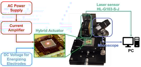
Figure 2.
Experiment setup.
The results of measurements for three squared proof masses of different sizes are jointly shown in Figure 3. At the beginning of each measurement, a PM was located on the surface of the electrode structure, and the output of the laser sensor was set to null. Then, the coils of the actuator were excited by the control circuit with an A/C electric current of 120 rms; the levitation height, h, from the electrode surface was measured. Keeping the value of the electric current in the coils, a PM was moved down by electrostatic force. The difference between the initial and actual levitation height was estimated at each point, as shown in Figure 3. The levitation heights for two squared PMs having the same side length of but different thicknesses of 25 μm and 10 μm were measured as 70 μm and 95 μm, respectively. The PM with a side length of and a thickness of 10 μm was levitated at a height of 94 μm.
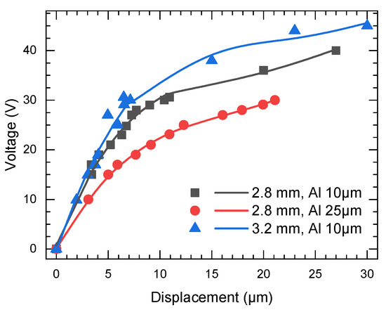
Figure 3.
Experimental results of the measurements of the displacements of the PMs under energizing electrodes “1” and “2”: circular points (red color) and squared points (gray color) correspond to the PMs having the same side length of but different thicknesses of 25 and 10 , respectively; triangular points (blue color) correspond to the PM having a side length of and a thickness of 10 .
The following pull-in parameters were observed. For the square PM having a side length of and a thickness of 25 μm, the pull-in displacement and voltage were 23 μm and 30 , respectively. For the square PM having the same side length but a thickness of 10 μm, the pull-in displacement and voltage were 30 μm and 40 , respectively. For the square PM having a side length of and a thickness of 10 μm, the pull-in displacement and voltage were 30 μm and 45 , respectively.
4. Simulation
For the simulation of the pull-in actuation, the quasi-FEM based on the n-CCA analogy was used [48]. The method involves two main steps. In the first step, the eddy current induced within the PM is calculated; in the second step, knowing the eddy current, the calculation of the electromagnetic force between the PM and coils is performed. According to the procedure [48], the following bases are introduced (the notations for vectors, bases, and matrices were adopted from the book of J. Wittenburg [52]). The fixed base , where () are the unit vectors of , and the exponent denotes the base number, as shown in Figure 4. The origin O of the fixed base is assigned to the center of the circular filament corresponding to the first top winding of the levitation coil, and the unit vectors and are lying on the filament plane, as shown in Figure 4. The base and corresponding unit vectors () are rigidly attached to the square-shaped PM so that its origin is located at the center of mass of the PM, and the unit vectors and are lying on the PM plane. The position of the origin of base with respect to the fixed base is defined by the radius vector , and its coordinates in base are , as shown in Figure 4. The position of each meshing element of the PM is defined by vector with respect to the base . Because the PM is a plane, the position of the sth meshing element has the following coordinates . The 3D geometry of two microcoils was approximated by a series of circular filaments, the number of which depends on the number of turns of the coil windings. Hence, the levitation coil was replaced by 20 circular filaments, while the stabilization coil was replaced by 12 circular filaments. Thus, the total number of circular filaments, N, was 32. The linear position of the jth circular filament of the coils can be defined by vector . Its coordinates for the jth winging of the levitation coil are , , where p is the pitch, equaling to 25 μm, as shown in Figure 4. The same is applicable for the stabilization coil, , with the difference being the index j being varied from 21 to 32.
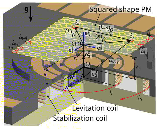
Figure 4.
Scheme for the simulation: is the fixed base; is the gravity acceleration vector directed along the -axis; is the base assigned to the center of mass (cm) of the PM; is the current in the j-circular loop of the coil; h is the levitation height estimated from the surface of the electrode structure; is the levitation height estimated from the top first winding of the coils.
4.1. Eddy Current Calculation
The PM with a side length of was homogenously meshed by 2500 circular elements of the same radius, 2.8025 × 10⁻⁵ m, as shown in Figure 5A. The result of meshing was a list of elements () containing information about a radius vector for each element with respect to the base . A position of the meshed PM relative to the circular filaments replacing the helix levitation and stabilization coil is shown in Figure 5B.
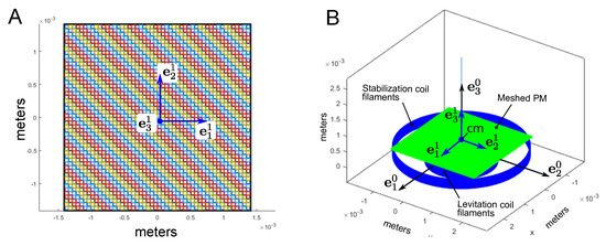
Figure 5.
(A) The square-shape PM with a side length of is meshed by 2500 circular elements with a radius of 2.8025 × 10⁻⁵ m; (B) 3D geometrical scheme of HLMA for eddy current simulation.
To calculate the eddy current within the PM, the following matrix of inductances was formed:
where is the unit matrix, is the -symmetric hollow matrix whose elements are the mutual inductance () between the sth and kth meshing element, and is the self-inductance of the circular element, which is calculated by the known formula for a circular ring with a circular cross-section
where is the magnetic permeability of free space, ; is the thickness of a mashed layer of the PM. The distance between the kth and sth meshing element is characterized by vector , as shown in Figure 4. Hence, the mutual inductance can be calculated as follows [43]:
where and are the dimensionless coordinates, and
and are the complete elliptic functions of the first and second kind, respectively.
Knowing the radius vector (see Figure 4), the mutual inductance between the s-meshing element and j-coil can be calculated similar to (4) as follows:
where
where , is the radius of the j-coil filament; , , and are the dimensionless components of the radius vector in base . Using Equation (7), the matrix consisting of elements of the mutual inductance is formed. Hence, the induced eddy current in each circular element is calculated as a solution of the following matrix equation:
where is the matrix of eddy currents , and is the given matrix of currents in coils. It is convenient to present the result of calculation in dimensionless form. For this reason, the dimensionless currents in the levitation and stabilization coils are introduced by dividing the currents on the amplitude of the current in the levitation coil because the amplitudes of the current in both coil are the same. Hence, the input current in the levitation coil filaments is one and that in the stabilization coil filaments is minus one (because of the 180° phase shift).
In order to illustratively present the calculation result, the obtained () eddy current matrix, , was transformed into a () 2D matrix, . The data in this () 2D matrix are located similarly to the structure corresponding to Figure 5A. Then, the distribution along the PM surface of the induced eddy current in the mesh circular elements is shown in Figure 6A. The analysis of Figure 6A shows that in a central area of the PM, corresponding to the area of the circular cross-section of the levitation coil, the eddy current has a negative sign (meaning that the direction of the induced eddy current flow is opposite to the flow direction in the levitation coil) due to the significant contribution of the A/C magnetic field generated by this coil. Outside of this area, the sign becomes positive due to the A/C magnetic field of the stabilization coil.
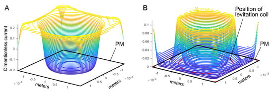
Figure 6.
The results of the eddy current calculation: (A) the distribution of the eddy current in mesh circular elements; (B) the distribution of the magnitudes of eddy current with respect to rhw unit vectors of and of the base .
The result in vector form through unit vectors and of the base is shown in Figure 6B. Taking the numerical gradient of the () 2D matrix with respect to the rows and columns, the components in the form of the () 2D matrixes of and relative to the unit vectors and were calculated, respectively. Then, the () 2D matrix of magnitudes of the eddy current for each mesh point was estimated by . The result of estimation is shown in Figure 6B. Figure 6B depicts that the maximum magnitudes of the eddy current are concentrated along the edge of the PM and in its central part along the circle having the same diameter as the levitation coil.
4.2. Pull-In Modeling
The linear displacement of the PM along the axis can be characterized by the generalized coordinate , similar to what was previously reported [48]. Hence, the quasi-FEM model can be written as
Then, Equation (11) is rewritten in dimensionless form:
where is the dimensionless time, is the displacement, is the squared voltage, , is the radius of the first winding of the levitation coil, , and are the dimensionless currents, , is the scaling factor, and is the spacing constant. Note that the spacing constant is responsible for the redistribution of electro-magnetic energy stored by the electrical field of the capacitors and the magnetic field of the coils and levitated PM, which occurs by changing the location of the electrodes along the axis. The derivative of the dimensionless mutual inductance with respect to [46] is
where
Accounting for (12), the static pull-in model based on quasi-FEM becomes
where the constant is defined at the equilibrium state as follows:
4.3. Square-Shapef Proof Mass with Side Length of 2.8 mm and Thickness of 10 μm
The PM was meshed by 2500 elements, as shown in Figure 5A. For the simulation, the 3D geometrical scheme, as shown in Figure 5B, with same dimensions for coils was used. The PM was levitated at a height of 95 measured from the surface of electrode structure, while the levitation height was estimated from the top first winding of the coils as 175 . Hence, the constants and were equal to and , respectively. The result of the simulation is shown in Figure 7. Figure 7A shows the result of the experimental measurements (cross points) and simulation (solid line) in terms of normalized voltage and dimensionless displacement . Figure 7B depicts a direct comparison between the experimental data and simulation results in absolute values. The model predicted the following pull-in parameters (see the circular solid point in Figure 7): the pull-in voltage is 39 , and the pull-in displacement is 34 .
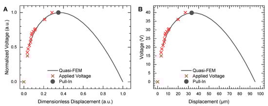
Figure 7.
Results of modeling for PM with a 2800 side length and thickness of 10 Al: (A) normalized voltage vs. dimensionless displacement; (B) voltage vs. displacement in absolute values.
4.4. Square-Shapes Proof Mass with Side Length of 2.8 mm and Thickness of 25 μm
The PM was meshed by 2500 elements, as shown in Figure 5A, and the same 3D geometrical scheme shown in Figure 5B was used. The height of levitation was measured as 70 from the surface of the electrode structure, while the levitation height was 150 . Hence, the constants and were and , respectively. The result of the simulation is shown in Figure 8. Figure 8A shows the result of the experimental measurements (cross points) and simulation (solid line) in terms of normalized voltage and dimensionless displacement . Figure 8B depicts a direct comparison between the experimental data and simulation in absolute values. The model predicted the following pull-in parameters (see the circular solid point in Figure 8): the pull-in voltage is 30 , and the pull-in displacement is 25 .
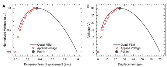
Figure 8.
Results of modeling for PM with a 2800 side length and a thickness of 25 Al: (A) normalized voltage vs. dimensionless displacement; (B) voltage vs. displacements in absolute values.
4.5. Square-Shaped Proof Mass with Side Length of 3.2 mm and Thickness of 10 μm
The PM was meshed by 2500 elements, while the radius of the meshing element was 3.2229 × 10⁻⁵ m. The height of levitation was 94 measured from the surface of the electrode structure, while the levitation height was 174 . The constants and were equal to and , respectively. The result of the simulation is shown in Figure 9. Figure 9A shows the result of the experimental measurements (cross points) and simulation (solid line) in terms of normalized voltage and dimensionless displacement . Figure 9B depicts the direct comparison between the experimental data and simulation in absolute values. The model predicted the following pull-in parameters (the circular solid point in Figure 9): the pull-in voltage is 46 , and the pull-in displacement is 35 .
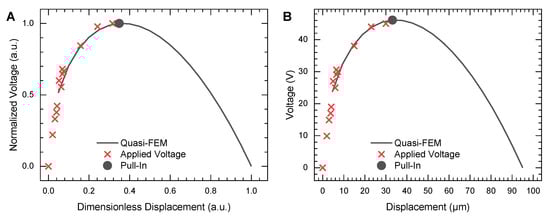
Figure 9.
Results of modeling for PM with a 3200 side length and a thickness of 25 Al: (A) normalized voltage vs. dimensionless displacement; (B) voltage vs. displacements in absolute values.
The results of the simulation and the measurements of pull-in parameters for the three PMs are summarized and tabulated in Table 1. The analysis of Table 1, Figure 7, Figure 8 and Figure 9 reveals a very good agreement between the proposed quasi-FEM model and measurement. Indeed, the developed model mimics the behaviors of the PMs displaced by electrostatic force as well as accurately predicts the parameters of pull-in actuation.

Table 1.
Results of measurements and modeling of the static pull-in actuation.
5. Conclusions
The pull-in actuation in a prototype of an HLMA with different sizes of square-shaped PMs was experimentally as well as theoretically studied. We experimentally demonstrated that the prototype using two coaxial 3D wire-bonded microcoils, namely, the stabilization and levitation coil with radii of and , was able stably levitate PMs with a side-length ranging from 2.7 to 3.3 . The pull-in actuation of the square-shaped PMs was performed by the electrostatic force generated by the set of energized electrodes and acting on the bottom surface of the PMs along the vertical direction. The experimental measurements showed that the pull-in actuation is nonlinearly dependent on the size and mass of the PM and the levitation height. In particular, we found that the PMs levitated within a range of a height from 140 to 170 can be displaced stably within a range of 30 . The results of measurements were extensively simulated by the analytical model Equation (11) that we developed by means of the quasi-FEM method based on the n-CCA analogy. The direct comparison of the results of the simulation and measurements showed a very good agreement between the theory and experimental results. Thus, the quasi-FEM approach combining the finite element method to calculate the induced eddy current and the differential equations describing the behavior of the mechanical part of the electromagnetic levitation system was shown to be a very efficient mathematical tool for the analysis and simulation of LMAs, including the stability, linear, and nonlinear dynamical responses.
Author Contributions
Conceptualization of the experiment, K.V.P. and E.R.M.; model development and extensive testing, K.V.P. and C.H.L.; device manufacturing and experimental testing, C.H.L. and E.R.M.; writing—original draft preparation, E.R.M., C.H.L. and K.V.P.; writing—review and editing, J.G.K., M.K. and K.V.P.; visualization K.V.P., E.R.M. and C.H.L.; supervision, E.R.M., J.G.K., M.K. and K.V.P.; project administration, E.R.M. and K.P; funding acquisition, K.V.P. and J.G.K. All authors have read and agreed to the published version of the manuscript.
Funding
This study was funded by Deutsche Forschungsgemeinschaft (DFG, German Research Foundation) under SPP 2206 priority program with grant number KO 1883/26-1.
Data Availability Statement
Not applicable.
Acknowledgments
C.H.L. and E.R.M. sincerely acknowledge A. N. Julius for her help with the proof mass and device dicing; M. Zakharova, A. Mikhailov, H. Fornasier, U. Köhler, and all cleanroom staff for their great cooperation, expertise, and advice on technological issues during device microfabrication. All authors acknowledge support by the KIT-Publication Fund of the Karlsruhe Institute of Technology.
Conflicts of Interest
The authors declare no conflict of interest.
Abbreviations
The following abbreviations are used in this manuscript:
| PM | Proof Mass |
| ELMA | Electric Levitation Microactuator |
| MLMA | Magnetic Levitation Microactuator |
| ILMA | Inductive Levitation Microactuator |
| HLMA | Hybrid Levitation Microactuator |
| Quasi-FEM | Quasi-Finite Element Method |
| UV lithography | Ultraviolet Lithography |
| DRIE | Deep Reactive Ion Etching |
| PCB | Printed Circuit Board |
| SOI | Silicon on Insulator |
References
- Poletkin, K.V.; Asadollahbaik, A.; Kampmann, R.; Korvink, J.G. Levitating Microactuators: A Review. Actuators 2018, 7, 17. [Google Scholar] [CrossRef]
- Jin, J.; Yih, T.C.; Higuchi, T.; Jeon, J.U. Direct electrostatic levitation and propulsion of silicon wafer. IEEE Trans. Ind. Appl. 1998, 34, 975–984. [Google Scholar] [CrossRef]
- Murakoshi, T.; Endo, Y.; Fukatsu, K.; Nakamura, S.; Esashi, M. Electrostatically levitated ring-shaped rotational gyro/accelerometer. Jpn. J. Appl. Phys 2003, 42, 2468–2472. [Google Scholar] [CrossRef]
- Han, F.; Liu, Y.; Wang, L.; Ma, G. Micromachined electrostatically suspended gyroscope with a spinning ring-shaped rotor. J. Micromech. Microeng. 2012, 22, 105032. [Google Scholar] [CrossRef]
- Han, F.; Sun, B.; Li, L.; Wu, Q. Performance of a sensitive micromachined accelerometer with an electrostatically suspended proof mass. IEEE Sens. J. 2015, 15, 209–217. [Google Scholar]
- Coombs, T.; Samad, I.; Ruiz-Alonso, D.; Tadinada, K. Superconducting microbearings. Appl. Supercond. IEEE Trans. 2005, 15, 2312–2315. [Google Scholar] [CrossRef]
- Lu, Z.; Poletkin, K.; den Hartogh, B.; Wallrabe, U.; Badilita, V. 3D micromachined inductive contactless suspension: Testing and Modeling. Sens. Actuators A Phys. 2014, 220, 134–143. [Google Scholar] [CrossRef]
- Poletkin, K.; Moazenzadeh, A.G.; Mariappan, S.; Lu, Z.; Wallrabe, U.; G. Korvink, J.; Badilita, V. Polymer Magnetic Composite Core Boosts Performance of 3D Micromachined Inductive Contactless Suspension. IEEE Magn. Lett. 2016, 7, 1–3. [Google Scholar] [CrossRef]
- Shearwood, C. Electro-magnetically levitated microdiscs. In Proceedings of the IEE Colloquium on Microengineering Applications in Optoelectronics, London, UK, 27 February 1996. [Google Scholar] [CrossRef]
- Shearwood, C.; Ho, K.; Williams, C.; Gong, H. Development of a levitated micromotor for application as a gyroscope. Sens. Actuators A Phys. 2000, 83, 85–92. [Google Scholar] [CrossRef]
- Su, Y.; Xiao, Z.; Ye, Z.; Takahata, K. Micromachined Graphite Rotor Based on Diamagnetic Levitation. IEEE Electron Device Lett. 2015, 36, 393–395. [Google Scholar] [CrossRef]
- Garmire, D.; Choo, H.; Kant, R.; Govindjee, S.; Sequin, C.; Muller, R.; Demmel, J. Diamagnetically levitated MEMS accelerometers. In Proceedings of the Solid-State Sensors, Actuators and Microsystems Conference, Anchorage, Alaska, 21–25 June 2007; pp. 1203–1206. [Google Scholar]
- Dieppedale, C.; Desloges, B.; Rostaing, H.; Delamare, J.; Cugat, O.; Meunier-Carus, J. Magnetic bistable microactuator with integrated permanent magnets. Sensors 2004, 1, 493–496. [Google Scholar]
- Abadie, J.; Piat, E.; Oster, S.; Boukallel, M. Modeling and experimentation of a passive low frequency nanoforce sensor based on diamagnetic levitation. Sens. Actuators A Phys. 2012, 173, 227–237. [Google Scholar] [CrossRef]
- Xu, Y.; Jiang, Q.; Yang, K.; Zhou, J.; Guo, Q. A novel ultra-high-resolution inclination sensor based on diamagnetic levitation. Sens. Actuators Phys. 2022, 343, 113686. [Google Scholar] [CrossRef]
- Zhang, K.; Su, Y.; Ding, J.; Gong, Q.; Duan, Z. Design and Analysis of a Gas Flowmeter Using Diamagnetic Levitation. IEEE Sens. J. 2018, 18, 6978–6985. [Google Scholar] [CrossRef]
- Hsu, A.; Chu, W.; Cowan, C.; McCoy, B.; Wong-Foy, A.; Pelrine, R.; Lake, J.; Ballard, J.; Randall, J. Diamagnetically levitated milli-robots for heterogeneous 3D assembly. J. microBio Robot. 2018, 14, 1–16. [Google Scholar] [CrossRef]
- Zhang, K.; Su, Y.; Ding, J.; Gong, Q.; Duan, Z. An airflow energy harvester using diamagnetic levitation structure. Energy Procedia 2019, 158, 595–600. [Google Scholar] [CrossRef]
- Chen, X.; Keskekler, A.; Alijani, F.; Steeneken, P.G. Rigid body dynamics of diamagnetically levitating graphite resonators. Appl. Phys. Lett. 2020, 116, 243505. [Google Scholar] [CrossRef]
- Liu, W.; Chen, W.Y.; Zhang, W.P.; Huang, X.G.; Zhang, Z.R. Variable-capacitance micromotor with levitated diamagnetic rotor. Electron. Lett. 2008, 44, 681–683. [Google Scholar] [CrossRef]
- Xu, Y.; Cui, Q.; Kan, R.; Bleuler, H.; Zhou, J. Realization of a diamagnetically levitating rotor driven by electrostatic field. IEEE/ASME Trans. Mechatronics 2017, 22, 2387–2391. [Google Scholar] [CrossRef]
- Xiao, Q.; Kraft, M.; Luo, Z.; Chen, J.; Wang, J. Design of contactless electromagnetic levitation and electrostatic driven rotation control system for a micro mirror. In Proceedings of the 2018 15th International Conference on Control, Automation, Robotics and Vision (ICARCV), Singapore, 18–21 November 2018; pp. 1176–1179. [Google Scholar]
- Sari, I.; Kraft, M. A MEMS Linear Accelerator for Levitated microobjects. Sens. Actuators A Phys. 2015, 222, 15–23. [Google Scholar] [CrossRef]
- Poletkin, K.; Lu, Z.; Wallrabe, U.; Badilita, V. A New Hybrid Micromachined Contactless Suspension with Linear and Angular Positioning and Adjustable Dynamics. J. Microelectromech. Syst. 2015, 24, 1248–1250. [Google Scholar] [CrossRef]
- Poletkin, K.V. A novel hybrid contactless cuspension with adjustable spring constant. In Proceedings of the 2017 19th International Conference on Solid-State Sensors, Actuators and Microsystems (TRANSDUCERS), Kaohsiung, Taiwan, 18–22 June 2017; pp. 934–937. [Google Scholar] [CrossRef]
- Poletkin, K.V.; Korvink, J.G. Modeling a Pull-In Instability in microMachined Hybrid Contactless Suspension. Actuators 2018, 7, 11. [Google Scholar] [CrossRef]
- Ciric, I. Electromagnetic levitation in axially symmetric systems. Rev. Roum. Sci. Tech. Ser. Electrotech. Energy 1970, 15, 35–73. [Google Scholar]
- Williams, C.; Shearwood, C.; Mellor, P.; Yates, R. Modelling and testing of a frictionless levitated micromotor. Sens. Actuators A Phys. 1997, 61, 469–473. [Google Scholar] [CrossRef]
- Zhang, W.; Chen, W.; Zhao, X.; Wu, X.; Liu, W.; Huang, X.; Shao, S. The study of an electromagnetic levitating micromotor for application in a rotating gyroscope. Sens. Actuators A Phys. 2006, 132, 651–657. [Google Scholar] [CrossRef]
- Liu, K.; Zhang, W.; Liu, W.; Chen, W.; Li, K.; Cui, F.; Li, S. An innovative microdiamagnetic levitation system with coils applied in microgyroscope. Microsyst. Technol. 2010, 16, 431. [Google Scholar] [CrossRef]
- Lu, Z.; Jia, F.; Korvink, J.; Wallrabe, U.; Badilita, V. Design optimization of an electromagnetic microlevitation system based on copper wirebonded coils. In Proceedings of the 2012 Power MEMS, Salt Lake City, UT, USA, 12–15 December 2012; pp. 363–366. [Google Scholar]
- Laithwaite, E. Electromagnetic levitation. Electr. Eng. Proc. Inst. Eng. 1965, 112, 2361–2375. [Google Scholar] [CrossRef]
- Levich, B.G. Theoretical Physics. An Advanced Text. Volume 2: Statistical Physics. Electromagnetic Processes in Matter; North-Holland Publishing: Amsterdam, The Netherlands; London, UK, 1971. [Google Scholar]
- Okress, E.; Wroughton, D.; Comenetz, G.; Brace, P.; Kelly, J. Electromagnetic levitation of solid and molten metals. J. Appl. Phys. 1952, 23, 545–552. [Google Scholar] [CrossRef]
- Poletkin, K.; Chernomorsky, A.I.; Shearwood, C.; Wallrabe, U. An analytical model of micromachined electromagnetic inductive contactless suspension. In Proceedings of the ASME 2013 International Mechanical Engineering Congress & Exposition, San Diego, CA, USA, 15–21 November 2013; ASME: San Diego, CA, USA, 2013; p. V010T11A072. [Google Scholar] [CrossRef]
- Poletkin, K.; Chernomorsky, A.; Shearwood, C.; Wallrabe, U. A qualitative analysis of designs of micromachined electromagnetic inductive contactless suspension. Int. J. Mech. Sci. 2014, 82, 110–121. [Google Scholar] [CrossRef]
- Skubov, D.; Popov, I.; Udalov, P. Induction Suspension of Conductive Microring and Its Gyroscopic Stabilization. 2021. Available online: https://www.researchsquare.com/article/rs-171012/latest.pdf (accessed on 3 January 2023).
- Udalov, P.; Lukin, A.; Popov, I.; Skubov, D. Analysis of the Equilibrium of a Magnetic Contactless Suspension. In Microactuators, Microsensors and Micromechanisms; Pandey, A.K., Pal, P., Nagahanumaiah, Zentner, L., Eds.; Springer International Publishing: Berlin/Heidelberg, Germany, 2023; pp. 183–190. [Google Scholar]
- Poletkin, K.V.; Chernomorsky, A.I.; Shearwood, C. A Proposal for Micromachined Accelerometer, based on a Contactless Suspension with Zero Spring Constant. IEEE Sens. J. 2012, 12, 2407–2413. [Google Scholar] [CrossRef]
- Poletkin, K. On the Static Pull-In of Tilting Actuation in Electromagnetically Levitating Hybrid Microactuator: Theory and Experiment. Actuators 2021, 10, 256. [Google Scholar] [CrossRef]
- Poletkin, K.; Lu, Z.; Wallrabe, U.; Korvink, J.; Badilita, V. Stable dynamics of micromachined inductive contactless suspensions. Int. J. Mech. Sci. 2017, 131–132, 753–766. [Google Scholar] [CrossRef]
- Babic, S.; Sirois, F.; Akyel, C.; Girardi, C. Mutual Inductance Calculation Between Circular Filaments Arbitrarily Positioned in Space: Alternative to Grover’s Formula. IEEE Trans. Magn. 2010, 46, 3591–3600. [Google Scholar] [CrossRef]
- Poletkin, K.V.; Korvink, J.G. Efficient calculation of the mutual inductance of arbitrarily oriented circular filaments via a generalisation of the Kalantarov-Zeitlin method. J. Magn. Magn. Mater. 2019, 483, 10–20. [Google Scholar] [CrossRef]
- Poletkin, K.V.; Babic, S.; Kumar, S.S.; Mamleyev, E.R. Calculation of Mutual Inductance between Circular and Arbitrarily Shaped Filaments via Segmentation Method. arXiv 2022, arXiv:2209.00464. [Google Scholar]
- Babic, S.; Akyel, C. Magnetic force between inclined circular filaments placed in any desired position. IEEE Trans. Magn. 2012, 48, 69–80. [Google Scholar] [CrossRef]
- Poletkin, K.V. Calculation of magnetic force and torque between two arbitrarily oriented circular filaments using Kalantarov–Zeitlin’s method. Int. J. Mech. Sci. 2022, 220, 107159. [Google Scholar] [CrossRef]
- Poletkin, K.; Babic, S. Magnetic stiffness calculation for the corresponding force between two current-carrying circular filaments arbitrarily oriented in the space. J. Magn. Magn. Mater. 2023, 568, 170067. [Google Scholar] [CrossRef]
- Poletkin, K. Static pull-in behavior of hybrid levitation microactuators: Simulation, modeling and experimental study. IEEE/ASME Trans. Mechatronics 2020, 26, 753–764. [Google Scholar] [CrossRef]
- Vlnieska, V.; Voigt, A.; Wadhwa, S.; Korvink, J.; Kohl, M.; Poletkin, K. Development of Control Circuit for Inductive Levitation Microactuators. Proceedings 2020, 64, 39. [Google Scholar] [CrossRef]
- Lee, C.H.; Kumar, S.S.; Mamleyev, E.; Poletkin, K. Characterisation of Static Pull-In Effect of Hybrid Levitation Microactuators for Square-Shaped Proof Masses. In Proceedings of the ACTUATOR 2022; International Conference and Exhibition on New Actuator Systems and Applications, Mannheim, Germany, 29–30 June 2022; pp. 1–4. [Google Scholar]
- Poletkin, K.; Lu, Z.; Wallrabe, U.; Badilita, V. Hybrid electromagnetic and electrostatic micromachined suspension with adjustable dynamics. J. Phys. Conf. Ser. 2015, 660, 012005. [Google Scholar] [CrossRef]
- Wittenburg, J. Dynamics of Multibody Systems; Springer: Berlin/Heidelberg, Germany, 2020; p. 223. [Google Scholar] [CrossRef]
Disclaimer/Publisher’s Note: The statements, opinions and data contained in all publications are solely those of the individual author(s) and contributor(s) and not of MDPI and/or the editor(s). MDPI and/or the editor(s) disclaim responsibility for any injury to people or property resulting from any ideas, methods, instructions or products referred to in the content. |
© 2023 by the authors. Licensee MDPI, Basel, Switzerland. This article is an open access article distributed under the terms and conditions of the Creative Commons Attribution (CC BY) license (https://creativecommons.org/licenses/by/4.0/).