Abstract
The finite control set model predictive torque control (FCS-MPTC) selects the optimal voltage vector (VV) by the composite cost function composed of torque and flux error, which makes it have a faster dynamic response than conventional control methods. However, the prediction state error caused by machine parameter mismatch and the difficulty in setting the weight factor in the composite cost function seriously restrict the popularization and application of FCS-MPTC. In this paper, a model-free parallel predictive torque control (MF-PPTC) based on an ultra-local (UL) model is proposed to solve above problems. The UL model replaces the machine mathematical model without any machine parameters and only uses the input and output of the system, which greatly improves the robustness of the control system. The nonlinear extended state observer proposed for the unknown part of the system has fast convergence and improves the dynamic performance of the system. In addition, the conventional parallel predictive control structure is optimized to reduce the dynamic adjustment process during the selection of optimal voltage vector. Simulation and experimental comparison between the conventional PPTC and the proposed MF-PPTC verified the superiority of the proposed method.
1. Introduction
The permanent magnet synchronous machine has attracted much attention because of its small size, high power density and high efficiency [1]. Many different machine control strategies are proposed to achieve high drive performance. At present, there are two widely used control strategies: field-oriented control (FOC) and direct torque control (DTC). Conventional FOC and DTC methods have their own advantages, specifically excellent steady-state and dynamic performance, simple structure and so on [2]. However, conventional FOC methods are limited by the fact that the control bandwidth cannot be adjusted in time to change the operating environment, and their dynamic performance is poor compared to their superior steady-state performance [3,4,5]. Similarly, the torque and flux ripple of conventional DTC method are obvious disadvantages [6].
At present, model predictive control (MPC) is regarded as an effective substitute for conventional control methods because of its simple structure and intuitive concept [7]. Finite control set model predictive control (FCS-MPC) is a branch of MPC which is more suitable for the control circuit of a two-level inverter with finite voltage vectors [8,9]. However, the conventional FCS-MPC still faces the following two main problems: one is that the weight factor in the coincidence cost function cannot be adjusted automatically with the change of operating environment, and second the machine parameter mismatching has great influence on its control performance [10]. For these two main problems, many excellent control algorithms have been proposed.
Many excellent control algorithms such as constraint normalization [11] and split cost function [12,13,14] have been proposed to solve the difficulty of weight factor setting in compound cost function. In [11], it is proposed to convert the torque and flux reference into equivalent parameter values of flux to eliminate the weight factor. However, the complex vector calculation process in this method increases the computational burden. In [12,13,14], the authors propose splitting the compound cost function into a single cost function form of a single constraint (torque error cost function and flux error cost function). Then, sequence control structure and parallel control structure are used to select the optimal voltage vector to avoid the weight factor setting process. The parallel prediction structure can balance the importance of multiple constraints in the process of optimal voltage vector selection [14].
On the other hand, many excellent control algorithms have been proposed to solve the problem of parameter mismatch and external disturbance, such as Luenberger observer [15], sliding mode observer [16,17], Kalman filter observer [18], interference compensation [19,20,21,22,23] and parameter identification [24,25]. In [15], current prediction errors caused by system disturbances are compensated by the proposed Romberg observer. Similarly, in [16,17], a new adaptive terminal sliding mode approach law and a high-order sliding mode observer were designed to estimate the total disturbance of the system, so as to improve the robustness of the system. In [18], a two-stage extended Kalman filter observer was proposed to estimate system load torque and disturbance, effectively improving the prediction process. In [19], an online current compensation method was proposed based on the improved disturbance observer of the augmented model. In [20], according to the error change between the predicted value and the actual value, the error caused by parameter mismatch is calculated in real-time to compensate the predicted current value. In [21,22,23], the observer was used to estimate the total disturbance of the system and carry out feedforward compensation for the control quantity. However, all of these methods have the problem of relying on a certain machine parameter or complicated calculation. In [24,25], offline and online identification methods of machine parameters are proposed, respectively. However, the offline identification method has a high specificity and can only be used for a specific machine, and there is a lot of preliminary work, so it is suitable for the condition that all machine parameters are unknown. The online identification method has heavy computation burden and high requirement on system hardware.
At present, a model-free control strategy is widely sought after because it does not need the mechanism model of the controlled object. In [26,27,28], model-free current control is realized by finding the relationship between current and inverter switching state. However, this method has more limitations, and has higher requirements on control frequency, sampling time and sensor accuracy. The model-free control method based on the UL model provides a new way to realize the control method without machine parameters [29,30,31]. In [29,30], the control principle of UL model and its application in a PMSM control system are introduced in detail. In [31], the UL model was applied in predictive current control, which improved the conventional model-free control method and showed good control effect in predictive control. However, the linear extended state observer used in this method performs poorly in dynamic performance, and the problem of weight factor in the composite cost function is not solved.
In this paper, a model-free parallel predictive torque control method based on the UL model is proposed to eliminate weight factors and suppress parameter mismatches. First, the conventional parallel predictive control structure is improved to reduce the automatic adjustment process in the conventional predictive control structure and make the selection process of optimal voltage vector more convenient. Second, a nonlinear extended state observer (NLESO) [32] is proposed to improve the conventional UL model, which has a faster convergence rate and provides a faster dynamic response capability for the system. Meanwhile, the existence of NLESO greatly improves the anti-interference capability of the system. Finally, simulation and experimental comparison between conventional PPTC and the proposed MF-PPTC verified the superiority of the proposed method.
The structure of this paper is as follows. In Section 2, the principle of conventional parallel predictive torque control is presented. In Section 3, the principle of model-free parallel predictive torque control based on a UL model is introduced. In Section 4 and Section 5, the comparison of simulation and experimental results of conventional PPTC and the proposed MF-PPTC is provided. Finally, this paper is concluded in Section 6.
2. Principle of Conventional Parallel Predictive Torque Control
The voltage and torque mathematical equations of surface permanent magnet synchronous machine (SPMSM) on the d-q axis can be expressed as follows [7]:
where , , , , , are stator voltage, stator current and stator flux linkage in rotating coordinate system, respectively; , , , , p are stator resistance, stator inductance, rotor flux linkage, mechanical angular velocity, and number of pole pair, respectively.
In the conventional FCS-MPTC, the future state of the machine is predicted through the Euler equation discretization Equations (1)–(3), which is presented as Equations (4) and (5) [9].
where and are the predicted correction and predictive value of the current, respectively, and and are the predictive value of flux and torque, respectively.
Then, the composite cost function in FCS-MPTC is determined as follows:
where N represents the prediction horizon, Q represents the weight factor and represents the maximum current, which is defined in [22]. The optimal VV is determined by minimizing the cost function. Unreasonable weighting factors have a serious impact on the performance of FCS-MPTC.
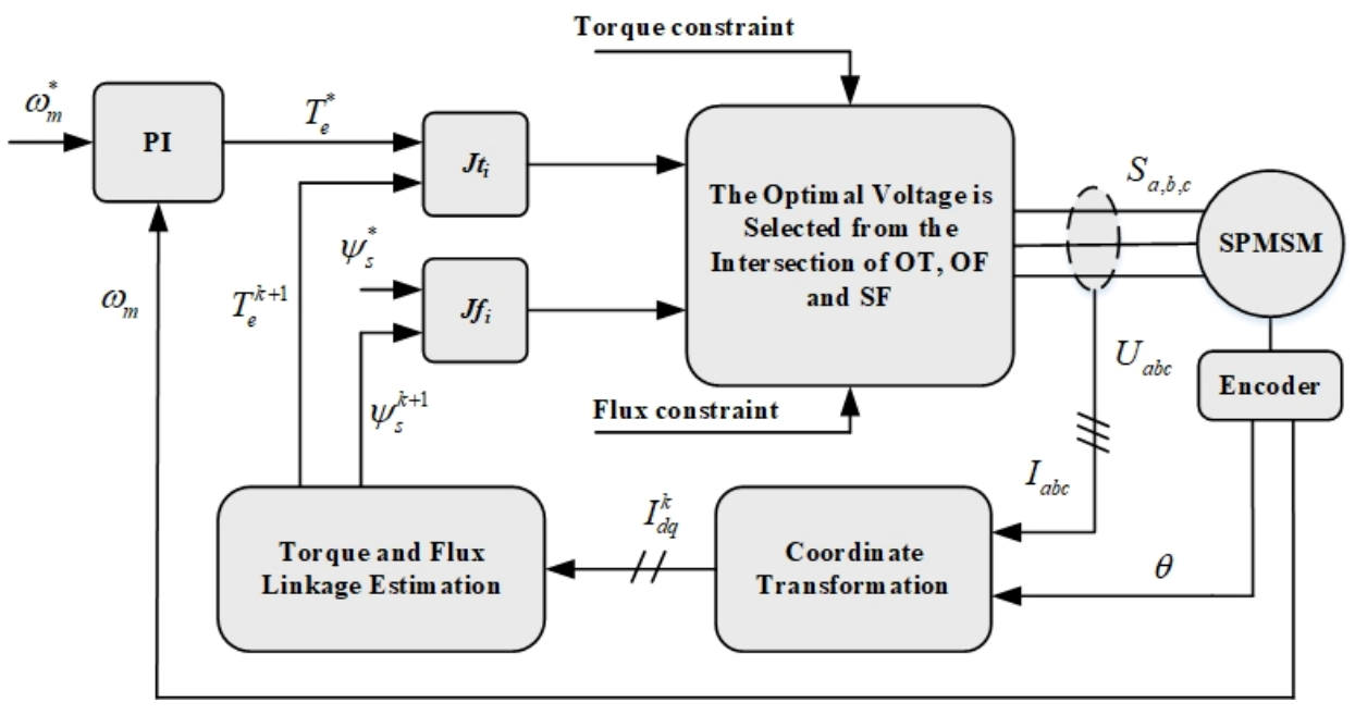
The conventional PPTC takes the independent cost function terms corresponding to torque and flux control as the alternative of the composite cost function, as shown in Equations (7) and (8) [8]. The control block diagram of conventional PPTC is illustrated in Figure 1.
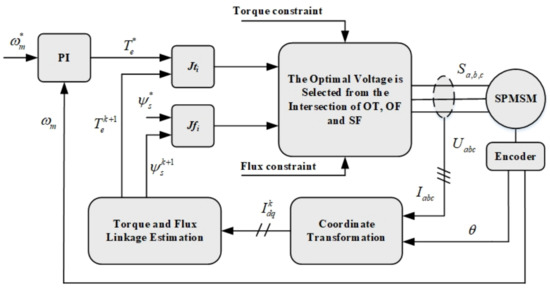
Figure 1.
The control block diagram of PPTC.
All eight VVs of the two-level inverter are classified into three candidate VV matrices through dynamic torque and flux boundary conditions. Then, the optimal VV at the next time is selected according to the intersection distribution between the three candidate VV matrices. The detailed algorithm is introduced in [8].
3. Principle of Model-Free Parallel Predictive Torque Control
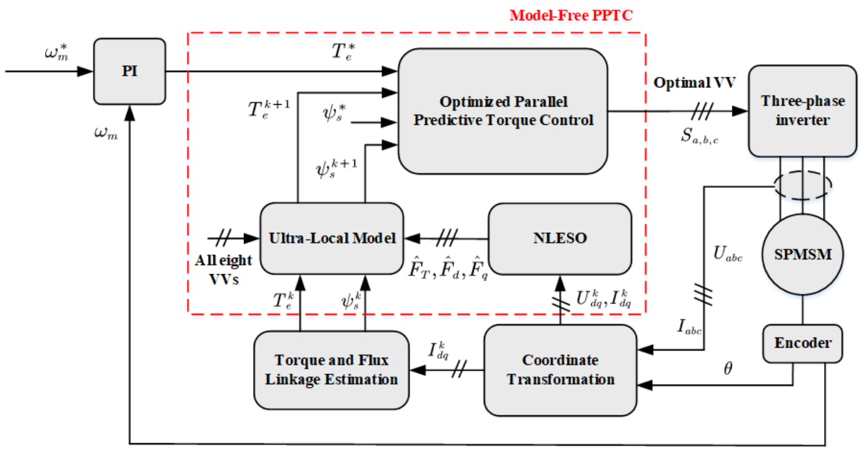
The system block diagram of proposed MF-PPTC is shown in Figure 2. The UL model block and optimized parallel predictive torque control block are used to eliminate parameter mismatch disturbance and weight factor in the conventional FCS-MPTC, respectively.
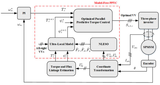
Figure 2.
The control block diagram of the proposed MF-PPTC.
3.1. Model Free Control Based on UL Model
The first-order nonlinear single-input single-output UL model can be expressed as follows [29]:
Then, the machine mathematical model Equations (1)–(3) can be reconstructed as the following hyperlocal model form:
where , and , , are input and output signals of the motor drive systemin UL model, respectively; , are scaling factors of the system input signals, respectively; , and represent unknown parts of the mathematical model of stator flux in rotating coordinate system and electromagnetic torque, respectively. Note that , and in Equation (10) represent unknown parts of the system model, and it is necessary to obtain accurate , and .
In order to obtain accurate , and values, a nonlinear extended state observer is adopted. Equation (10) is replaced by Equation (9) to facilitate calculation and derivation. The error feedback equation can be obtained as follows [32]:
where represents state variable, represents extended state variable; denotes the estimated value of the output variable y; denotes the estimated value of the state variable , and ; denotes the input variable; and denote the error feedback gains, respectively; is the value of the nonlinear function at , as shown in Equation (12).
Note that guarantees fast convergence of state variables and to y and F in the case of reasonable values of and .
According to Equations (9) and (12), the following formula can be obtained can be obtained:
where , , is the derivative of the unknown part F of the system.
It can be seen from Equation (13) that is a smooth curve, and and . Then, in Equation (13) can be written as the first-order Taylor expansion of at as shown in Equation (14).
Let ,, then Equation (15) can be rewritten as follows:
where , , . The necessary condition for the asymptotic stability of Equation (16) under the influence of is that all the eigenvalues of A fall on the negative half plane of the complex plane [32]. Reasonable poles can be determined by the following characteristic equation:
where I stands for unit matrix. By making the polynomial coefficients at both ends of Equation (17) equal, the coefficients and can be obtained. Note that reasonable poles are determined according to operating conditions and control requirements.The final expression of the nonlinear extended state observer is
By substituting into the following equation, the predicted value at can be obtained:
3.2. Optimized Parallel Predictive Torque Control
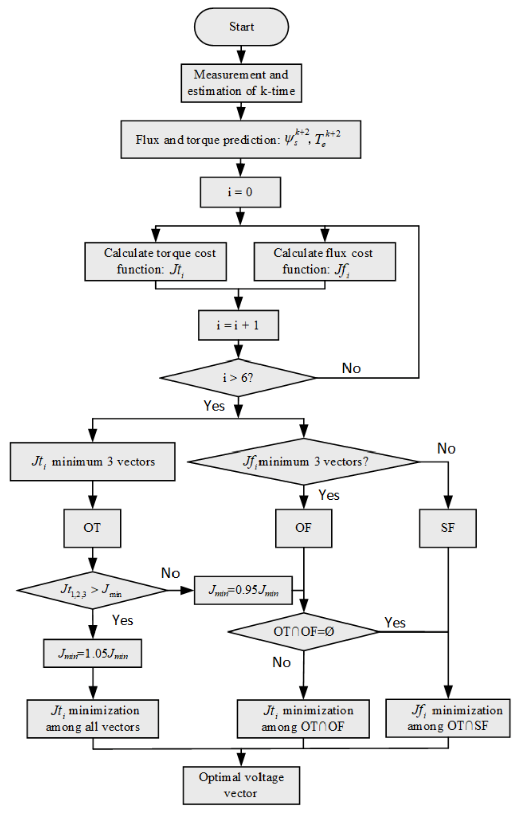
In the conventional PPTC method, the candidate VV matrix is classified by dynamic torque and flux constraints, and the number of elements in the candidate VV matrix is maintained at 2–4 [13]. According to the analysis results in [12], it is reasonable that the number of candidate VVs determined by torque and flux constraints is three. The greater the number of VVs, the lower the priority of the constraint. Therefore, dynamic constraints can lead to instability of system. On the basis of the conventional PPTC, the dynamic constraints are discarded, and the three VVs that minimize the cost function among the torque and flux cost functions ( and ) calculated from all eight VVs are directly stored in the optimal torque () candidate matrix and the optimal flux () candidate matrix. The remaining five VVs that make the value of flux cost function larger are stored in the suboptimal flux () candidate matrix. Then, the optimal VV is selected according to the intersection between the candidate VV matrices (, and ) and the operating conditions of the machine. The system control flow chart is shown in Figure 3.
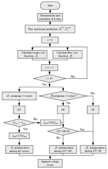
Figure 3.
The control flow chart of the proposed MF-PPTC.
4. Performance Evaluation Simulation
In order to verify the superior response performance of the proposed MF-PPTC, the response performances of the proposed MF-PPTC and conventional PPTC are compared in the MATLAB/Simulink environment. The machine parameters are given in Table 1. The NLESO parameters of the proposed MF-PPTC are shown in Table 2. The simulated switching frequency is 20 kHz. The PI parameters of the speed outer loop of the conventional PPTC are designed according to those in [13], and those of MF-PPTC are obtained according to the same method. The reference value of electromagnetic torque is obtained from the PI controller, and the reference value of stator flux is given by the maximum torque per ampere (MTPA). According to the average value range of initial constraint of electromagnetic torque under different operating conditions provided in [14], the in proposed MF-PPTC is set to 0.8 N.m. The speed reference value is 100 r/min before 0.5 s, and increases from 100 r/min to 1000 r/min with constant acceleration during 0.5 s to 1 s, and keeps stable operation at 1000 r/min after 1 s. The load torque is set to a sine wave with a minimum of 2 N.m and a maximum of 4 N.m and a frequency of 2 Hz.

Table 1.
Machine parameters.
Table 2.
Observer parameters.
4.1. Simulation with Precise Parameters
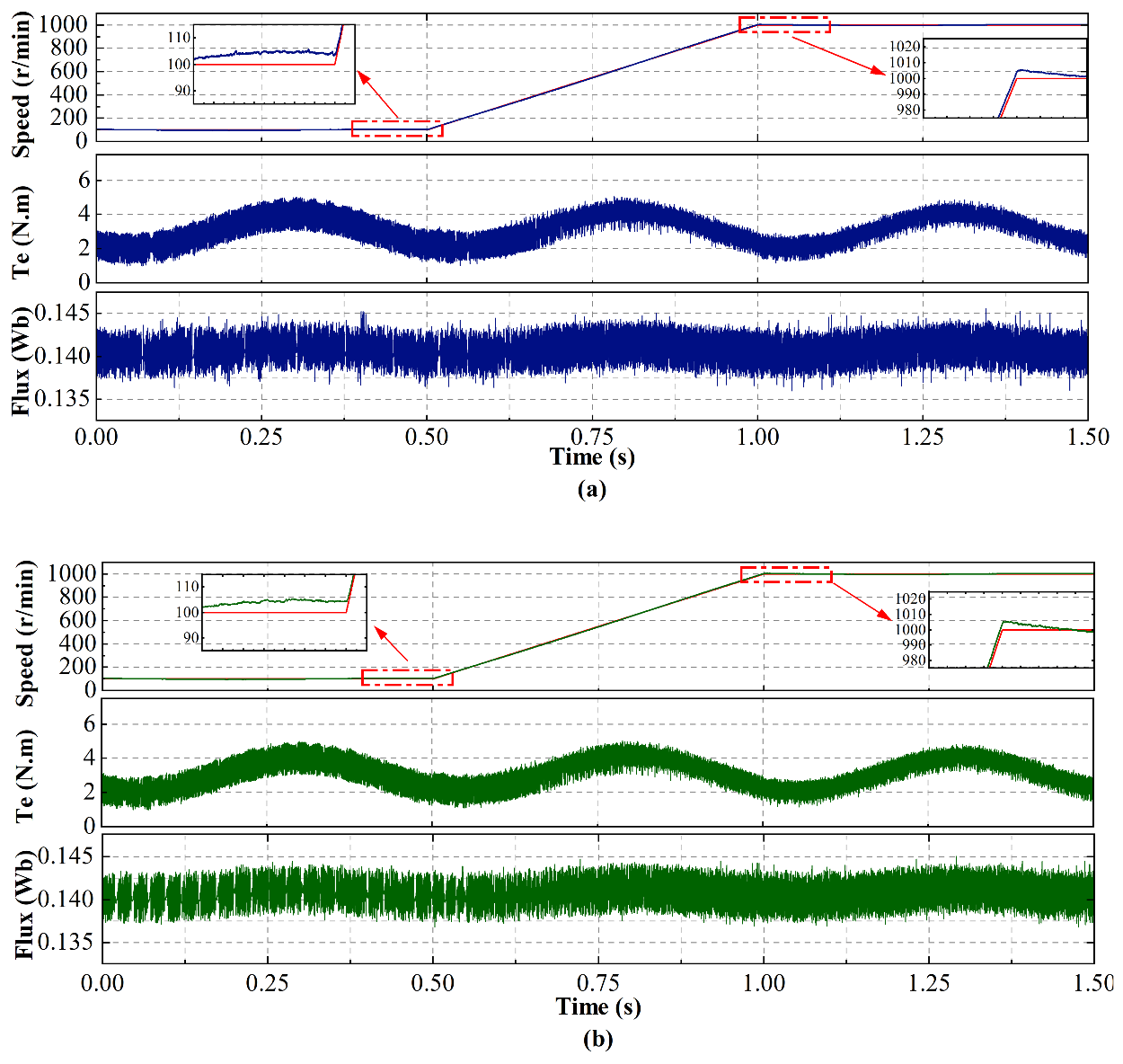
Figure 4 illustrates the simulation results of the conventional PPTC and the proposed MF-PPTC with precise parameters under the dynamic conditions of speed and torque. Proposed MF-PPTC and conventional PPTC both have slight overshoot when the speed changes at 0.5 s and 1 s and can track the speed reference well during 0.5 s to 1 s. The electromagnetic torque fluctuation of proposed MF-PPTC and conventional PPTC at 100 r/min is larger than that at 1000 r/min; the performance of the two control strategies at low speed is slightly worse than that at high speed. Although the reference value of stator flux is derived from the electromagnetic torque reference value via MTPA, it has strong robustness to the sinusoidal disturbance of the reference value of electromagnetic torque. The response performance can be evaluated according to the ITAE described in [7], as given

Figure 4.
The simulation results of the conventional PPTC and the proposed MF-PPTC with precise parameters. (a) Conventional PPTC. (b) Proposed MF-PPTC.
In the whole simulation process, the ITAE values of proposed MF-PPTC’s speed and torque are 9.77 and 2.893, respectively, and those of conventional PPTC are 9.83 and 2.939, respectively. To sum up, the dynamic performance of the proposed MF-PPTC is similar to that of the conventional PPTC under precise parameters.
4.2. Simulation with Mismatched Parameters
Figure 5 shows the simulation results of conventional PPTC and proposed MF-PPTC under the condition of dynamic speed and load torque with mismatched parameters ( pu and pu). Compared with Figure 4a, with precise parameters, according to Figure 5a, the overshoot of speed becomes larger at 0.5 s and 1 s, the electromagnetic torque of the conventional PPTC has more burrs at low speed; the fluctuation of stator flux becomes larger, the stator flux has more burrs, and the robustness of the sinusoidal disturbance of electromagnetic torque is reduced. Compared with Figure 4b with precise parameters, according to Figure 5b, the speed of proposed MF-PPTC fluctuates slightly at low speed, the electromagnetic torque of proposed MF-PPTC is insensitive to parameters mismatch, the fluctuation of stator flux becomes larger, and the stator flux has more burrs. According to Figure 5a,b, compared with conventional PPTC under parameters mismatch, proposed MF-PPTC has smaller speed overshoot, fewer burrs in electromagnetic torque at low speeds and in stator flux at high speed, and stronger robustness to the sinusoidal disturbance of electromagnetic torque. In conclusion, although proposed MF-PPTC is also affected by parameters mismatch, the overall dynamic performance is better than that of conventional PPTC.
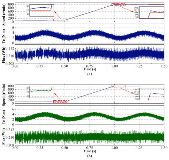
Figure 5.
The simulation results of conventional PPTC and proposed MF-PPTC with mismatched parameters. (a) Conventional PPTC. (b) Proposed MF-PPTC.
4.3. Simulation with Mismatched Parameters under Steady State
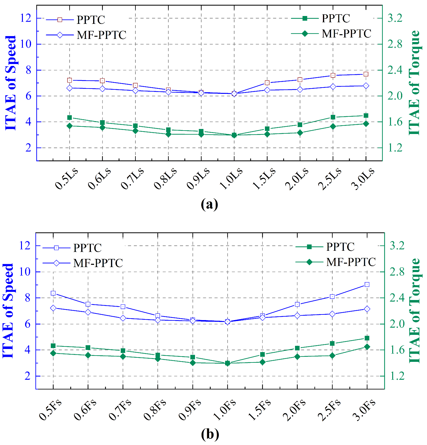
In order to further compare and analyze the effect of parameters mismatch on the conventional PPTC and the proposed MF-PPTC, the steady-state performance with the variation of stator inductance and rotor flux linkage is simulated within 2 s at 1000 r/min. According to Figure 6, when the parameters are precise, the speed and torque ITAE values of the two control strategies under steady state are approximately equal, which is consistent with the simulation conclusion with precise parameters.
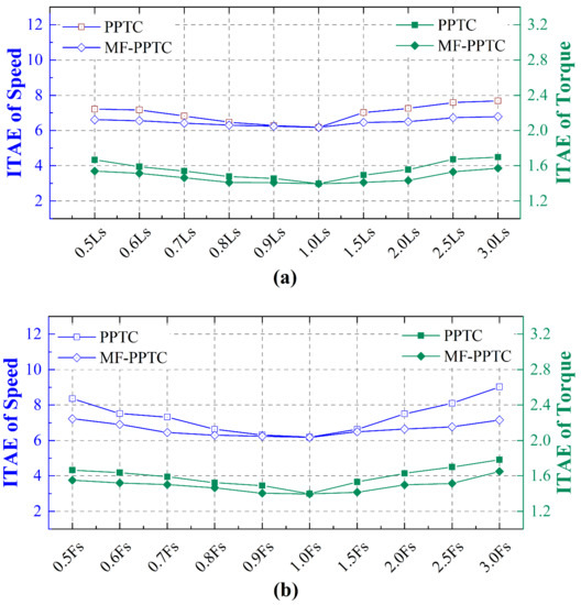
Figure 6.
The simulation results of speed and torque ITAE values with mismatched parameters. (a) Variation of inductance. (b) Variation of flux.
When the stator inductance or rotor flux increases (or decreases) from 1 pu, the ITAE values of the speed and torque of the conventional PPTC increase, and the minimum values are at 1 pu. When the variations of stator inductance and rotor flux are between −20% and 50%, the conventional PPTC can alleviate the influence of parameters mismatch on the performance of system. However, when the variation is beyond this range, the ITAE values of speed and torque increase greatly. When the stator inductance changes in the given range, the maximum ITAE variations of speed and torque of conventional PPTC are 1.503 and 0.298, respectively; When the rotor flux changes in the given range, the maximum ITAE variations of speed and torque of conventional PPTC are 2.846 and 0.385, respectively.
The ITAE variation trends of the proposed MF-PPTC speed and torque with parameters are similar to conventional PPTC, but the ITAE values of proposed MF-PPTC speed and torque are generally smaller than those of conventional PPTC. When the variations of stator inductance and rotor flux exceed the range of approximately −20% to 50%, the ITAE variations of speed and torque of proposed MF-PPTC are smaller than those of conventional PPTC. When the stator inductance changes in the given range, the maximum ITAE variations of speed and torque of proposed MF-PPTC are 0.611 and 0.178, respectively. When the rotor flux changes in the given range, the maximum ITAE variations of speed and torque of proposed MF-PPTC are 1.048 and 0.255, respectively. To sum up, in steady state, although the robustness of conventional PPTC is good in the case of slight parameters mismatch, its robustness becomes worse in the case of serious parameters mismatch. The proposed MF-PPTC can effectively suppress the influence of parameters mismatch on system performance, regardless of whether the mismatch of parameters is minor or severe.
5. Performance Evaluation Experiment
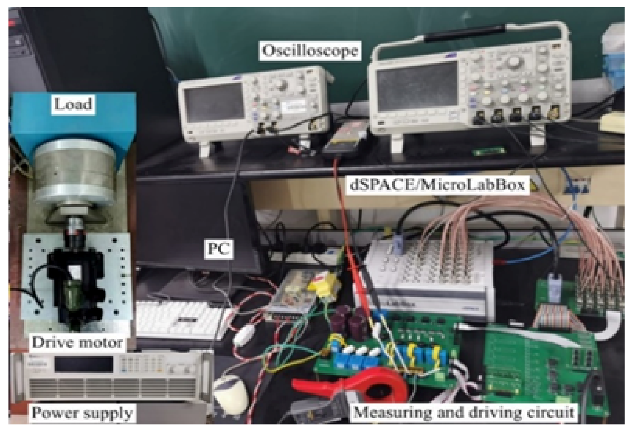
Experimental tests on conventional PPTC and MF-PPTC proposed in this paper are carried out on a driving platform consisting of dSPACE/MicroLabBox and 1 kW PMSM (110SJT-M040D), as shown in the Figure 7. The control circuit consists of a power supply (62050H-600s), a two-level inverter (PM50CLA120) and a measuring circuit. The voltage and current sensors used in the experimental platform are CHV-25P and LA-50P Hall sensors, respectively. The conditioning circuit contains a filter current of 10 kHz. The machine speed and position signal are measured by 2500-line incremental encoder. The machine parameters are shown in Table 1. The experimental parameters to be set are consistent with the simulation parameters, and the switching frequency of two-level inverter is 20 kHz.
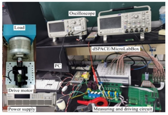
Figure 7.
Experimental platform.
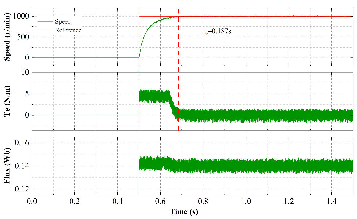
5.1. No-Load Start-Up Experiment of Proposed MF-PPTC
At 0.5 s, the machine starts up and accelerates to 1000 r/min, and keeps this speed running under no-load condition. The no-load start-up experimental result of proposed MF-PPTC is shown in Figure 8. It can be seen from Figure 8 that the dynamic response time of speed is 0.187 s, and the stator flux has good robustness to the electromagnetic torque disturbance. When the machine runs stably at 1000 r/min, the electromagnetic torque and stator flux fluctuate in the range of −1.47 N.m–1.387 N.m and 0.135 Wb–0.146 Wb, respectively.
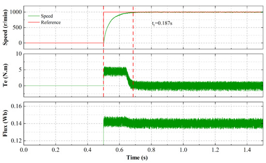
Figure 8.
The no-load start-up experimental result of proposed MF-PPTC.
5.2. Experimental Evaluation of Stator Inductance Mismatch
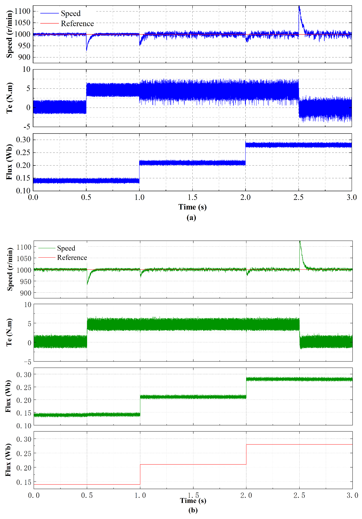
At a constant speed of 1000 r/min, the machine is loaded from no-load to rated load at 0.5 s, the stator inductance increases from 1 pu to 1.5 pu at 1 s, the stator inductance increases to 2 pu at 2 s and the load is reduced to no-load at 2.5 s. The experimental results of the conventional PPTC [13] and the proposed MF-PPTC in the case of stator inductance mismatch are shown in Figure 9.
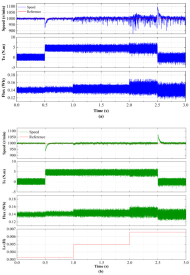
Figure 9.
The experimental results of conventional PPTC and proposed MF-PPTC in the case of stator inductance mismatch. (a) Conventional PPTC. (b) Proposed MF-PPTC.
According to Figure 9a, the steady-state speed performance of the conventional PPTC is good when pu; The speed fluctuation becomes larger and has more burrs when pu, and when the stator inductance is 2 pu, the speed fluctuation is very severe. Compared with pu, the electromagnetic torque of conventional PPTC has more burrs when pu, the electromagnetic torque fluctuation becomes larger when pu. At rated load, the electromagnetic torque fluctuations of conventional PPTC under different stator inductance are 2.82 N.m–6.56 N.m, 1.24 N.m–6.96 N.m and 0.56 N.m–7.64 N.m respectively. With the increase of stator inductance variation, the stator flux fluctuation of conventional PPTC increases, and the stator flux fluctuations of different stator inductance under rated load are 0.131 Wb–0.153 Wb, 0.1275 Wb–0.1596 Wb and 0.124 Wb–0.1705 Wb respectively.
According to Figure 9b, under the condition of stator inductance mismatch, the speed fluctuation of proposed MF-PPTC becomes slightly larger. When pu, the electromagnetic torque performance of proposed MF-PPTC is identical to that of accurate stator inductance, and the electromagnetic torque fluctuation becomes larger when pu. At rated load, the electromagnetic torque fluctuations of conventional PPTC under different stator inductance are 2.84 N.m–6.49 N.m, 2.03 N.m–6.63 N.m and 1.874 N.m–6.76 N.m, respectively. With the increase of stator inductance, the stator flux fluctuation becomes larger. The stator flux fluctuations of different stator inductance under rated load are 0.133 Wb–0.15 Wb, 0.13 Wb–0.157 Wb and 0.128 Wb–0.164 Wb, respectively.
In conclusion, compared with conventional PPTC, proposed MF-PPTC with stator inductance mismatch has stable speed performance and little fluctuation. The electromagnetic torque can still maintain the performance of precise parameters when pu, and the electromagnetic torque fluctuation is smaller than that of conventional PPTC when pu. Although the stator flux fluctuation of MF-PPTC and conventional PPTC both increase when the parameters are mismatched, the stator flux of proposed MF-PPTC is less sensitive to stator inductance mismatch.
5.3. Experimental Evaluation of Rotor Flux Mismatch
The operating conditions of speed and load under rotor flux mismatch are consistent with those of stator inductance mismatching experiment. The rotor flux increases from 1 pu to 1.5 pu at 1 s, and it increases to 2 pu at 2 s. MTPA needs to use rotor flux to calculate the stator flux reference. When the rotor flux is mismatched, the rotor flux is modified in the MTPA of the control strategy to ensure the system performance. At this time, the stator flux reference value will change with the rotor flux change. The experimental results of conventional PPTC and proposed MF-PPTC in the case of rotor flux mismatch are shown in Figure 10.
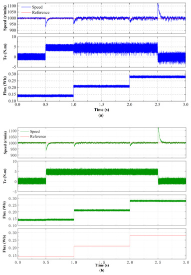
Figure 10.
The experimental results of conventional PPTC and proposed MF-PPTC in the case of rotor flux mismatch. (a) Conventional PPTC. (b) Proposed MF-PPTC.
According to Figure 10a, when the rotor flux mismatch, the fluctuation of speed and electromagnetic torque of conventional PPTC becomes larger, the electromagnetic torque has more burrs, and stator flux performance is good. At rated load, the fluctuations of electromagnetic torque and stator flux under different rotor flux are 2.82–6.56 N.m, 0.48–7.62 N.m, 0.532–7.56 N.m, 0.1283–0.1523 Wb, 0.198–0.223 Wb and 0.268–0.295 Wb respectively.
According to Figure 10b, when there exists rotor flux mismatch, the performance of the proposed MF-PPTC is the same as that when the rotor flux is precise. At rated load, the fluctuation of electromagnetic torque under different is 2.84–6.49 N.m, 2.89–6.67 N.m and 2.88–6.68 N.m; The fluctuations of stator flux under different are 0.1332–0.15 Wb, 0.202–0.22 Wb and 0.272–0.2895 Wb, respectively. In summary, the speed and electromagnetic torque of the conventional PPTC fluctuate greatly under the rotor flux mismatch, while the proposed MF-PPTC can maintain the same performance as normal operation under this circumstance. The performance comparisons are shown in Table 3. According to the performance comparison, it can be found that the proposed MF-PPTC shows better control performance for dealing with parameter mismatch and external disturbance.
Table 3.
Performance comparisons.
6. Conclusions
In this paper, a model-free parallel predictive torque control method based on the UL model is proposed, which improves the algorithm of the conventional parallel predictive control structure without weighting factors and combines the model-free control method to effectively improve the robustness of the system while ensuring the performance of the system. Meanwhile, the NLESO can greatly improve the dynamic and steady performance of the system with fast convergence rate. Upon comparative study of the conventional PPTC and the proposed MF-PPTC algorithm, our analysis shows that the proposed MF-PPTC algorithm is more effective than the conventional algorithm in dynamic and steady-state response performance and reducing the sensitivity of machine parameters. Simulation and experimental results show that compared with conventional PPTC, the proposed MF-PPTC exhibits stronger robustness under the influence of inductance and flux mismatch. Under the influence of inductance mismatch, the maximum variation of speed and torque ITAE of conventional PPTC is 2.5 and 1.7 times that of MF-PPTC, respectively. However, under the condition of flux mismatch, the maximum variation of speed and torque ITAE of conventional PPTC is 2.8 and 1.5 times of that of MF-PPTC, respectively. In addition, the experimental results show that proposed MF-PPTC has better speed performance, electromagnetic torque and stator flux fluctuation than the conventional PPTC.
Author Contributions
Conceptualization, H.Q. and D.Z.; methodology, M.L. and S.G.; software, M.L., S.G. and Y.W. (Yao Wei); validation, Y.W. (Yanjun Wei) and D.Z.; formal analysis, Y.W. (Yanjun Wei); writing—original draft preparation, M.L.; writing—review and editing, S.G. and Y.W. (Yanjun Wei). All authors have read and agreed to the published version of the manuscript.
Funding
This research was funded by the Natural Science Foundation of Hebei Province grant number E2019203297 and the Youth Fund Project of Science and Technology Program for Colleges and Universities of Hebei Provincial Education Department under Grant QN2018134.
Institutional Review Board Statement
Not applicable.
Informed Consent Statement
Not applicable.
Data Availability Statement
Not applicable.
Conflicts of Interest
The authors declare no conflict of interest.
Abbreviations
The following abbreviations are used in this manuscript:
| FCS-MPTC | Infinite control set model predictive torque control |
| MPCC | Model predictive current control |
| PPTC | parallel predictive torque control |
| MF-PPTC | Model-Free parallel predictive torque control |
| PMSM | Permanent magnet synchronous machine |
| TSEKF | two-stage extended Kalman filter |
| NLESO | Nonlinear extended state observer |
| FOC | Field-oriented control |
| DTC | Direct torque control |
| VV | Voltage Vector |
| OT | Optimal torque |
| OF | Optimal flux |
| SF | Suboptimal flux |
| ITAE | Integrated time and absolute error |
References
- Pillay, P.; Krishnan, R. Modeling, simulation, and analysis of permanent-magnet motor drives. I. The permanent-magnet synchronous motor drive. IEEE Trans. Ind. Appl. 1989, 25, 265–273. [Google Scholar] [CrossRef]
- Casadei, D.; Profumo, F.; Serra, G.; Tani, A. FOC and DTC: Two viable schemes for induction motors torque control. IEEE Trans. Power Electron. 2002, 17, 779–787. [Google Scholar] [CrossRef] [Green Version]
- Dini, P.; Saponara, S. Cogging Torque Reduction in Brushless Motors by a Nonlinear Control Technique. Energies 2019, 12, 2224. [Google Scholar] [CrossRef] [Green Version]
- Dini, P.; Saponara, S. Design of an Observer-Based Architecture and Non-Linear Control Algorithm for Cogging Torque Reduction in Synchronous Motors. Energies 2020, 13, 2077. [Google Scholar] [CrossRef]
- Ubare, P.; Ingole, D.; Sonawane, D. Nonlinear Model Predictive Control of BLDC Motor with State Estimation. IFAC-PapersOnLine 2021, 54, 107–112. [Google Scholar] [CrossRef]
- Zhong, L.; Rahman, M.; Hu, W.; Lim, K. Analysis of direct torque control in permanent magnet synchronous motor drives. IEEE Trans. Power Electron. 1997, 12, 528–536. [Google Scholar] [CrossRef]
- Wei, Y.; Wei, Y.; Sun, Y.; Qi, H.; Guo, X. Prediction Horizons Optimized Nonlinear Predictive Control for Permanent Magnet Synchronous Motor Position System. IEEE Trans. Ind. Electron. 2020, 67, 9153–9163. [Google Scholar] [CrossRef]
- Preindl, M.; Bolognani, S. Model Predictive Direct Torque Control with Finite Control Set for PMSM Drive Systems, Part 1: Maximum Torque Per Ampere Operation. IEEE Trans. Ind. Inform. 2013, 9, 1912–1921. [Google Scholar] [CrossRef]
- Xie, W.; Wang, X.; Wang, F.; Xu, W.; Kennel, R.M.; Gerling, D.; Lorenz, R.D. Finite-Control-Set Model Predictive Torque Control with a Deadbeat Solution for PMSM Drives. IEEE Trans. Ind. Electron. 2015, 62, 5402–5410. [Google Scholar] [CrossRef]
- Gao, S.; Wei, Y.; Zhang, D.; Qi, H.; Wei, Y. A Modified Model Predictive Torque Control with Parameters Robustness Improvement for PMSM of Electric Vehicles. Actuators 2021, 10, 132. [Google Scholar] [CrossRef]
- Zhang, Y.; Yang, H. An improved two-vectors-based model predictive torque control without weighting factors for induction motor drives. In Proceedings of the 2014 17th International Conference on Electrical Machines and Systems (ICEMS), Hangzhou, China, 22–25 October 2014; pp. 2766–2772. [Google Scholar]
- Zhang, Y.; Zhang, B.; Yang, H.; Norambuena, M.; Rodriguez, J. Generalized Sequential Model Predictive Control of IM Drives with Field-Weakening Ability. IEEE Trans. Power Electron. 2019, 34, 8944–8955. [Google Scholar] [CrossRef]
- Wang, F.; Xie, H.; Chen, Q.; Davari, S.A.; Rodríguez, J.; Kennel, R. Parallel Predictive Torque Control for Induction Machines without Weighting Factors. IEEE Trans. Power Electron. 2020, 35, 1779–1788. [Google Scholar] [CrossRef]
- Xie, H.; Wang, F.; He, Y.; Rodriguez, J.; Kennel, R. Encoderless Parallel Predictive Torque Control for Induction Machine Using A Robust Model Reference Adaptive System. IEEE Trans. Energy Convers. 2021. [Google Scholar] [CrossRef]
- Wang, B.; Chen, X.; Yu, Y.; Wang, G.; Xu, D. Robust Predictive Current Control With Online Disturbance Estimation for Induction Machine Drives. IEEE Trans. Power Electron. 2017, 32, 4663–4674. [Google Scholar] [CrossRef]
- Junejo, A.K.; Xu, W.; Mu, C.; Ismail, M.M.; Liu, Y. Adaptive Speed Control of PMSM Drive System Based a New Sliding-Mode Reaching Law. IEEE Trans. Power Electron. 2020, 35, 12110–12121. [Google Scholar] [CrossRef]
- Jiang, Y.; Xu, W.; Mu, C.; Liu, Y. Improved Deadbeat Predictive Current Control Combined Sliding Mode Strategy for PMSM Drive System. IEEE Trans. Veh. Technol. 2018, 67, 251–263. [Google Scholar] [CrossRef]
- Mwasilu, F.; Nguyen, H.T.; Choi, H.H.; Jung, J.W. Finite Set Model Predictive Control of Interior PM Synchronous Motor Drives With an External Disturbance Rejection Technique. IEEE/ASME Trans. Mechatron. 2017, 22, 762–773. [Google Scholar] [CrossRef]
- Jia, C.; Wang, X.; Liang, Y.; Zhou, K. Robust Current Controller for IPMSM Drives Based on Explicit Model Predictive Control with Online Disturbance Observer. IEEE Access 2019, 7, 45898–45910. [Google Scholar] [CrossRef]
- Yuan, X.; Zhang, S.; Zhang, C.; Galassini, A.; Buticchi, G.; Degano, M. Improved Model Predictive Current Control for SPMSM Drives Using Current Update Mechanism. IEEE Trans. Ind. Electron. 2021, 68, 1938–1948. [Google Scholar] [CrossRef]
- Xu, C.; Han, Z.; Lu, S. Deadbeat Predictive Current Control for Permanent Magnet Synchronous Machines with Closed-Form Error Compensation. IEEE Trans. Power Electron. 2020, 35, 5018–5030. [Google Scholar] [CrossRef]
- Yan, L.; Dou, M.; Hua, Z.; Zhang, H.; Yang, J. Robustness Improvement of FCS-MPTC for Induction Machine Drives Using Disturbance Feedforward Compensation Technique. IEEE Trans. Power Electron. 2019, 34, 2874–2886. [Google Scholar] [CrossRef]
- Yan, L.; Wang, F.; Dou, M.; Zhang, Z.; Kennel, R.; Rodríguez, J. Active Disturbance-Rejection-Based Speed Control in Model Predictive Control for Induction Machines. IEEE Trans. Ind. Electron. 2020, 67, 2574–2584. [Google Scholar] [CrossRef]
- Wang, Q.; Zhang, G.; Wang, G.; Li, C.; Xu, D. Offline Parameter Self-Learning Method for General-Purpose PMSM Drives with Estimation Error Compensation. IEEE Trans. Power Electron. 2019, 34, 11103–11115. [Google Scholar] [CrossRef]
- Dang, D.Q.; Rafaq, M.S.; Choi, H.H.; Jung, J.W. Online Parameter Estimation Technique for Adaptive Control Applications of Interior PM Synchronous Motor Drives. IEEE Trans. Ind. Electron. 2016, 63, 1438–1449. [Google Scholar] [CrossRef]
- Lin, C.K.; Liu, T.H.; Yu, J.T.; Fu, L.C.; Hsiao, C.F. Model-Free Predictive Current Control for Interior Permanent-Magnet Synchronous Motor Drives Based on Current Difference Detection Technique. IEEE Trans. Ind. Electron. 2014, 61, 667–681. [Google Scholar] [CrossRef]
- Agustin, C.A.; Yu, J.T.; Cheng, Y.S.; Lin, C.K.; Huang, H.Q.; Lai, Y.S. Model-Free Predictive Current Control for SynRM Drives Based on Optimized Modulation of Triple-Voltage-Vector. IEEE Access 2021, 9, 130472–130483. [Google Scholar] [CrossRef]
- Carlet, P.G.; Tinazzi, F.; Bolognani, S.; Zigliotto, M. An Effective Model-Free Predictive Current Control for Synchronous Reluctance Motor Drives. IEEE Trans. Ind. Appl. 2019, 55, 3781–3790. [Google Scholar] [CrossRef] [Green Version]
- Fliess, M.; Join, C. Model-free control. Int. J. Control 2013, 86, 2228–2252. [Google Scholar] [CrossRef] [Green Version]
- Zhou, Y.; Li, H.; Yao, H. Model-free control of surface mounted PMSM drive system. In Proceedings of the 2016 IEEE International Conference on Industrial Technology (ICIT), Taipei, Taiwan, 14–17 March 2016; pp. 175–180. [Google Scholar]
- Zhang, Y.; Jiang, T.; Jiao, J. Model-Free Predictive Current Control of DFIG Based on an Extended State Observer Under Unbalanced and Distorted Grid. IEEE Trans. Power Electron. 2020, 35, 8130–8139. [Google Scholar] [CrossRef]
- Gao, Z. Active disturbance rejection control: From an enduring idea to an emerging technology. In Proceedings of the 2015 10th International Workshop on Robot Motion and Control (RoMoCo), Poznan, Poland, 6–8 July 2015; pp. 269–282. [Google Scholar]


Publisher’s Note: MDPI stays neutral with regard to jurisdictional claims in published maps and institutional affiliations. |
© 2022 by the authors. Licensee MDPI, Basel, Switzerland. This article is an open access article distributed under the terms and conditions of the Creative Commons Attribution (CC BY) license (https://creativecommons.org/licenses/by/4.0/).