Article

Displacement Calculation of a Multi-Stage Homogeneous Loess Slope Under Seismic Action

1
School of Civil Engineering, Lanzhou Institute of Technology, Lanzhou 730050, China
2
School of Civil Engineering, Lanzhou University of Technology, Lanzhou 730050, China
3
School of Civil Engineering, Chongqing University, Chongqing 400045, China
4
School of Civil Engineering, Shandong University, Jinan 250061, China
5
Third Construction Co., Ltd. of China Construction Fifth Engineering Bureau, Changsha 410004, China
*
Author to whom correspondence should be addressed.
Buildings 2025, 15(9), 1484; https://doi.org/10.3390/buildings15091484
Submission received: 2 April 2025 / Revised: 22 April 2025 / Accepted: 25 April 2025 / Published: 27 April 2025
(This article belongs to the Special Issue Soil–Structure Interactions for Civil Infrastructure)

Abstract

Slope instability often brings serious threats to human production and life, which causes huge economic losses. The slope displacement calculation under seismic action is very important to ensure the safety and stability of a slope. At present, there are few studies on the displacement calculation of multi-stage loess slopes under seismic action. Based on the basic theory of soil dynamics and the introduction of the comprehensive slope ratio, this paper proposes a new displacement calculating method of multi-stage homogeneous loess slopes under seismic action and provides the calculation formula. The rationality of the theoretical calculation is verified using the numerical simulation software Geo Studio (V2022). The study shows that it is feasible to simplify the geometric characteristics of multi-stage loess slopes by adopting the comprehensive slope ratio, which can also reasonably reflect the displacement characteristics of multi-stage loess slopes under seismic action. The example verification shows that the deviation of the peak horizontal displacement between the calculating method of this paper and the numerical simulation result is 5.5%, which shows that the calculation method of this paper is reasonable and has a certain application value.

1. Introduction

Earthquakes pose a serious threat to the safety and stability of slopes, and slope instability under seismic action often results in huge economic losses and may also cause casualties [1,2,3]. The slope displacement calculation under seismic action is very important to ensure the safety and stability of a slope. At present, the pseudo-static method [4,5] and the pseudo-dynamic method [6,7,8,9] are often used to solve slope displacement under seismic action. Santo [10] analyzed the stability of three slopes under seismic action in Rangamati Hill using the pseudo-static method and determined the boundary condition using the pseudo-static method based on seismic force variation. Zheng [11] studied the seismic active earth pressure of rigid retaining walls based on the pseudo-static method, analyzed the calculation formula and characteristics of the seismic inertia force dispersed in the soil body, and concentrated on the centroid of the sliding soil wedge. Nayek [12] proposed a new data-driven Newmark sliding displacement prediction model based on the ANN, which can predict slope displacement using different combinations of ground motion intensity parameters and slope critical acceleration values. Takaji [13] proposed the spring-supported Newmark model by adding a linear spring to the slider of the conventional Newmark model and proved the repeatability of the key slope sliding behavior in the model tests. Dong [14] took a slope supported by a prestressed frame anchor as the research object and studied the seismic response of the soil body behind the slope and frame prestressed anchor using a relevant theory of soil dynamics. Wang [15] established the dynamic motion equation of unsupported slope under horizontal seismic action based on soil dynamics and provided a calculation method of the slope model dynamic parameters. Wei [16] established the dynamic motion equation of the slope supported by anti-slide pile under horizontal seismic action based on the basic theory of soil dynamics and analyzed the rationality of analytical solutions for the slope soil horizontal displacement response under horizontal seismic action.
In summary, it can be seen that the pseudo-static method is widely used, but it ignores the dynamic characteristics of the seismic force changing with time [17,18]. Additionally, the pseudo-dynamic method usually needs to be solved by numerical simulation software, which makes the calculation process more complicated and conservative [19]. In addition, the research objects of existing theoretical studies are mostly single-stage slopes, and numerical simulation software is more often used for multi-stage slopes. Therefore, theoretical research on the displacement calculation of multi-stage loess slopes under seismic action needs to be further deepened [20]. Compared to single-stage slopes, multi-stage slopes exhibit significantly more complex geometric configurations characterized by variations in slope stages, slope height, slope ratio, and unloading platform width. These geometric complexities result in distinct failure mechanisms under seismic loading, including potential localized failures due to stress redistribution and geometric discontinuities. The unloading platform, a defining feature of multi-stage slopes, plays a dual role: while it enhances global stability by mitigating progressive failure, its presence introduces additional analytical challenges due to the interaction between slope segments. To address this issue, a simplified analytical framework based on the comprehensive slope ratio is proposed, which enables the transformation of intricate multi-stage slope profiles into equivalent single-stage representations. Although this simplification does not fully account for geometric intricacies, localized stress concentrations, or irregular unloading platform effects, it provides a computationally efficient and practical approach for preliminary seismic stability assessment. The research results can provide a theoretical basis and practical reference for the stability analysis and engineering design of multi-stage slopes.

2. Effect of the Comprehensive Slope Ratio on Slope Displacement

Compared with single-stage slopes, multi-stage slopes exhibit complex geometric structures, where variations in slope stages, slope heights, slope ratios, and the width of the unloading platforms result in different failure mechanisms under seismic loads. Additionally, due to stress redistribution and geometric discontinuities, local failures may occur. The unloading platform is a key feature of multi-stage slopes, which enhances overall stability by reducing progressive failure, but it also introduces analytical complexity. To address this issue, a simplified approach is proposed to introduce a comprehensive slope ratio, converting a complex multi-stage slope into an equivalent single-stage slope profile for analysis. Although this simplification cannot fully capture the geometric complexity, stress concentration zones, or local variations in irregular unloading platforms, it provides a computationally efficient and practical solution for preliminary stability assessment under seismic conditions.

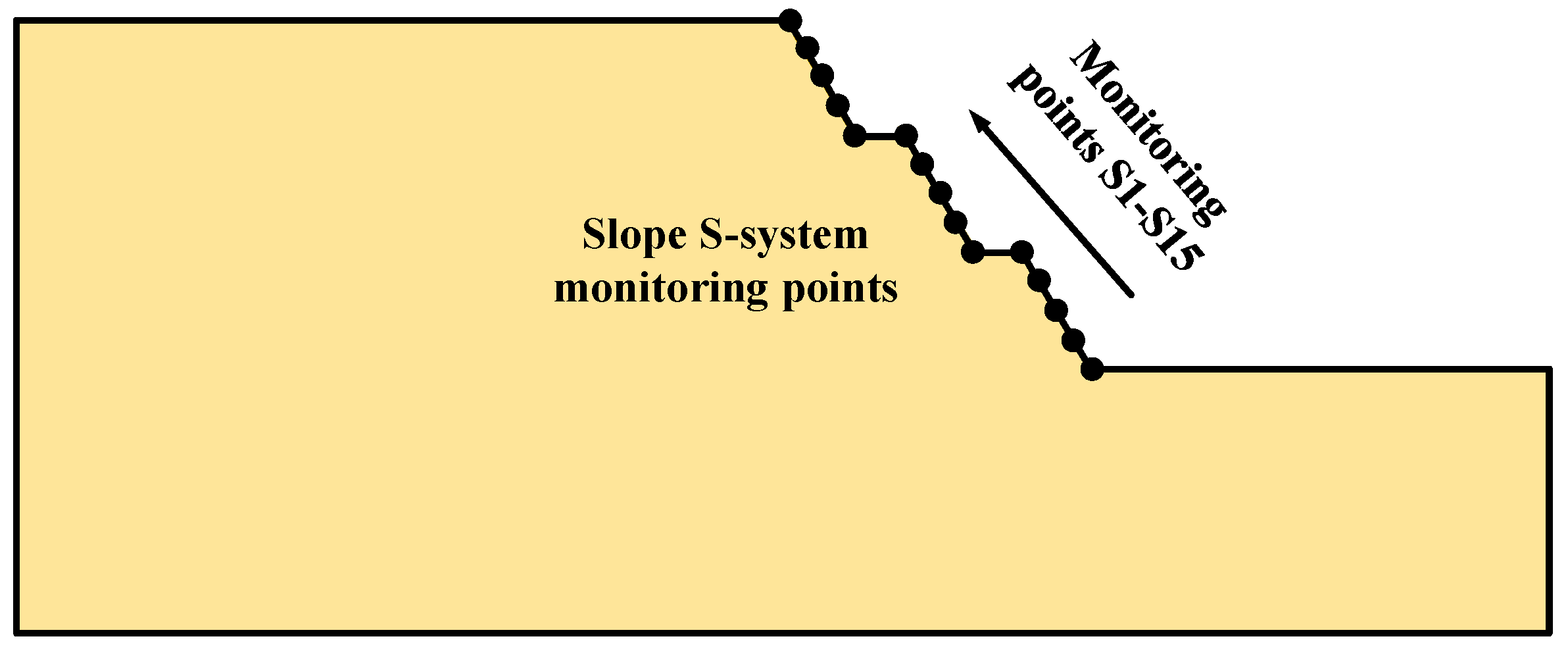
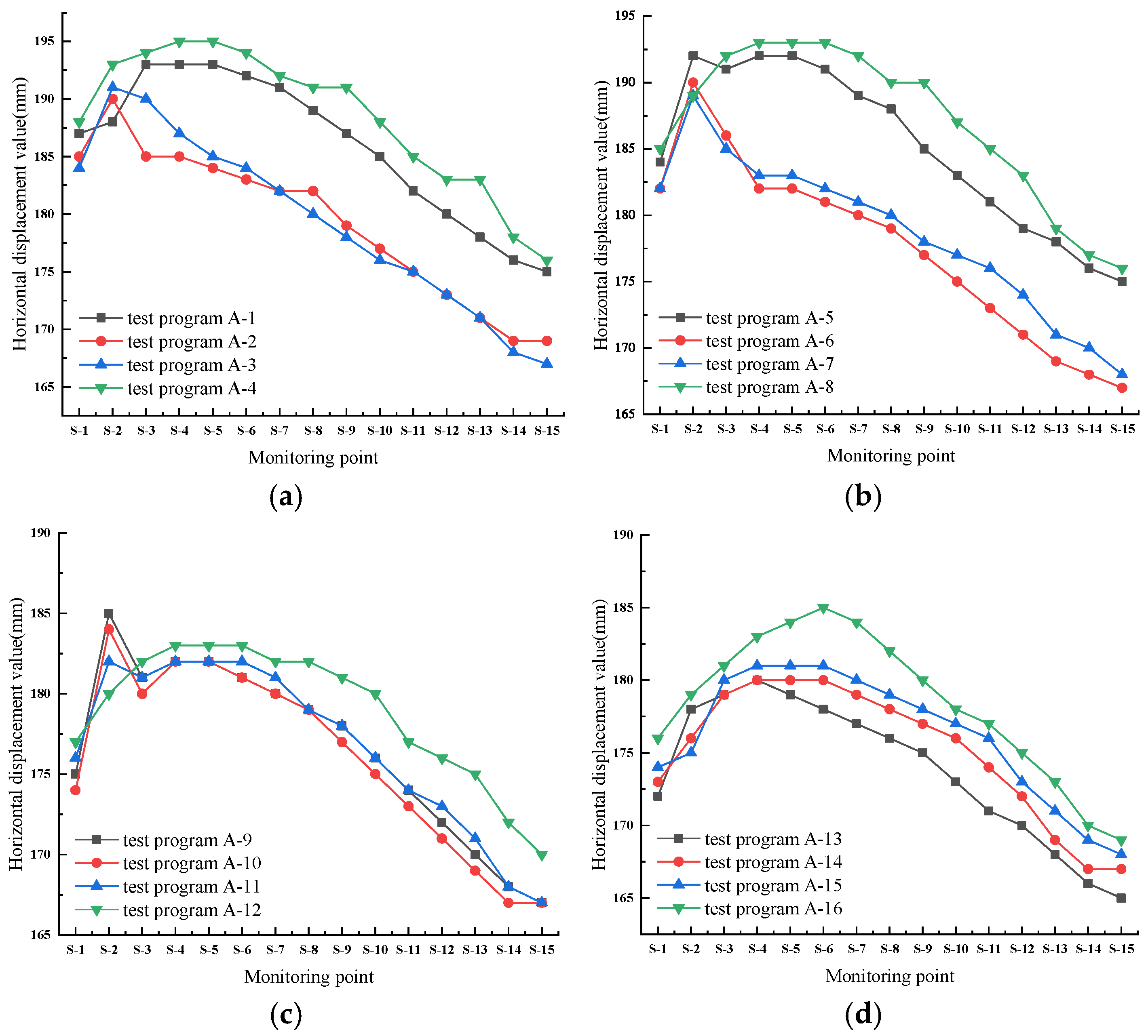
2.1. Influence of the Number of Slope Stages on the Multi-Stage Loess Slope Displacement

In this paper, 16 groups of single-factor influence tests are designed to further verify the rationality of using the comprehensive slope ratio to analyze the displacement of multi-stage loess slopes under seismic action, and the numerical simulation software Geo Studio is used to solve the problem. The multi-stage loess slope model was established by changing the number of slope stages. The total slope height H of the model is 30 m. The platform width B is 3 m. The natural gravity of the soil body γ is 16.8 kN/ m 3 . The Poisson’s ratio v is 0.3. The selected horizontal dynamic load is sinusoidal. The peak acceleration is 0.2 g, the seismic frequency f is 2.0 Hz, and the duration t is 10 s. In addition, the slope ratio of each stage under the same working condition is consistent, and the test conditions are shown in the following Table 1.
According to the test condition, Geo Studio is used to establish the calculation model of the slope under seismic action. The slope soil of the model is linearly elastic, and the yield rule is Mohr–Coulomb. The boundary condition of the initial state is that the two ends of the slope bottom are fixed, and the elevation direction is fixed horizontally. The boundary condition in the dynamic stage is that the two ends of the slope bottom are fixed, and the elevation direction is fixed vertically. When analyzing the effect of the comprehensive slope ratio on slope displacement, Wang [21] did not investigate displacement at the location of the slope face. For multi-stage slopes, the comprehensive slope ratio may have an effect on the displacement at different locations of the slope face. In order to analyze the effect of changes in the slope stage on displacement, 15 monitoring points are arranged along the model slope surface, numbered S1–S15. The vertical distance between the monitoring points is 2.5 m, and the arrangement of monitoring points for working condition A-3 is shown in Figure 1. The arrangement of monitoring points for other working conditions is the same as that of A-3.
Seismic action will lead to changes in the displacement, velocity, and acceleration of the soil body inside the slope, of which horizontal displacement is the main factor in the deformation and damage of the slope. This paper establishes the slope finite element model for each working condition. The horizontal displacement of the monitoring points on the slope’s surface for each working condition is extracted, and the extreme value of horizontal displacement is compared and analyzed. The distribution of final state horizontal displacement at each monitoring point under different comprehensive slope ratios is shown in Figure 2.
As can be seen from Figure 2, the distribution law of slope surface horizontal displacement under different comprehensive slope ratios is basically the same, and the overall trend is first increases and then decreases along the direction of the slope height. The horizontal displacement of the slope surface is larger when the comprehensive slope ratio is 1:0.75, which is consistent with the findings in the literature [22]. In addition, for the same composite slope ratio, the horizontal displacement of the slope’s surface changes significantly with the increase in the number of slope stages. As can be seen in Figure 2c, the difference between the horizontal displacements of working conditions A-5 and A-6 is the largest, which is 10 mm, and the deviation is 5.5%. This indicates that it is feasible to calculate the displacement of multi-stage slopes using the comprehensive slope ratio when the comprehensive slope ratio is constant and the number of slope stages changes.

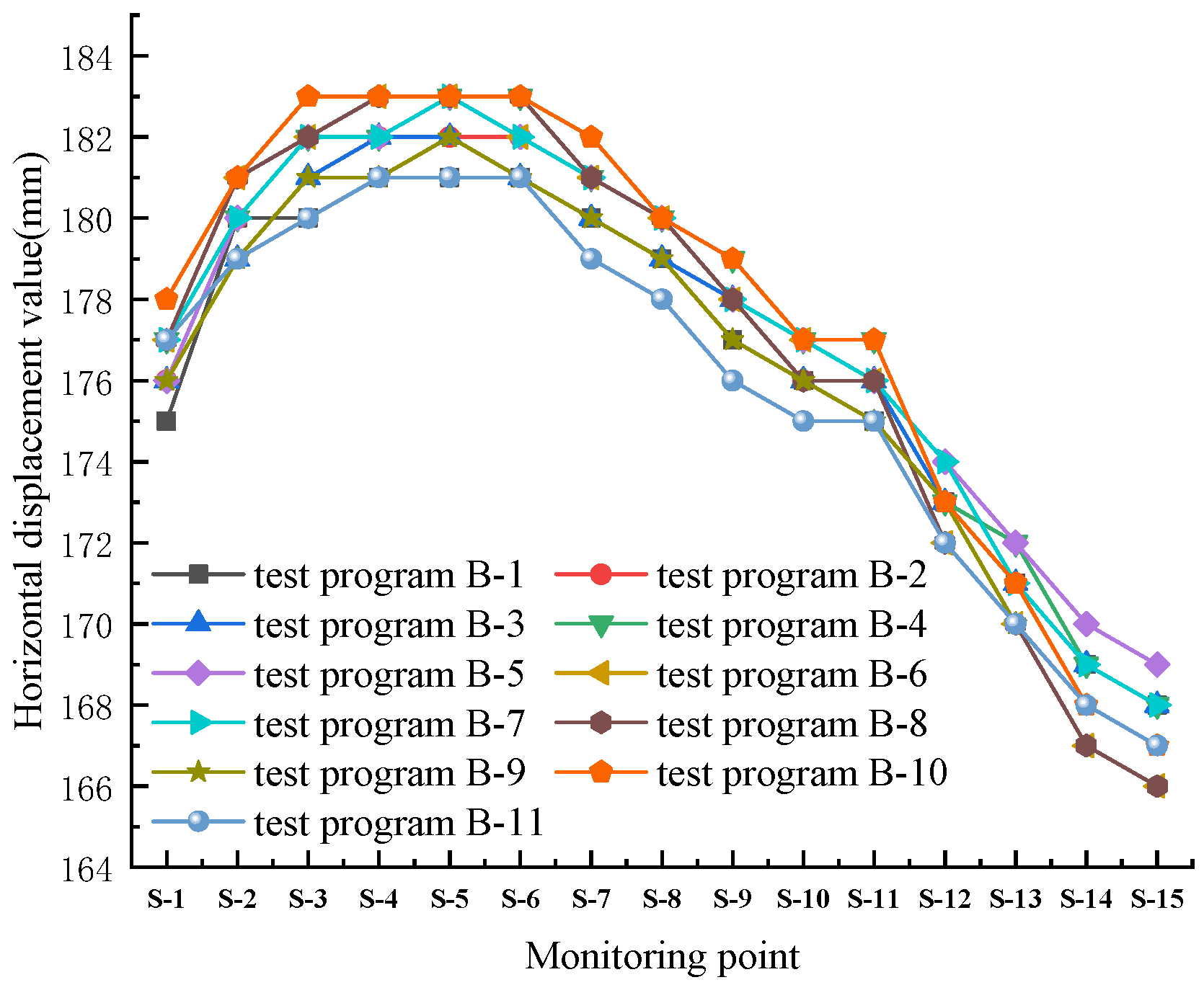
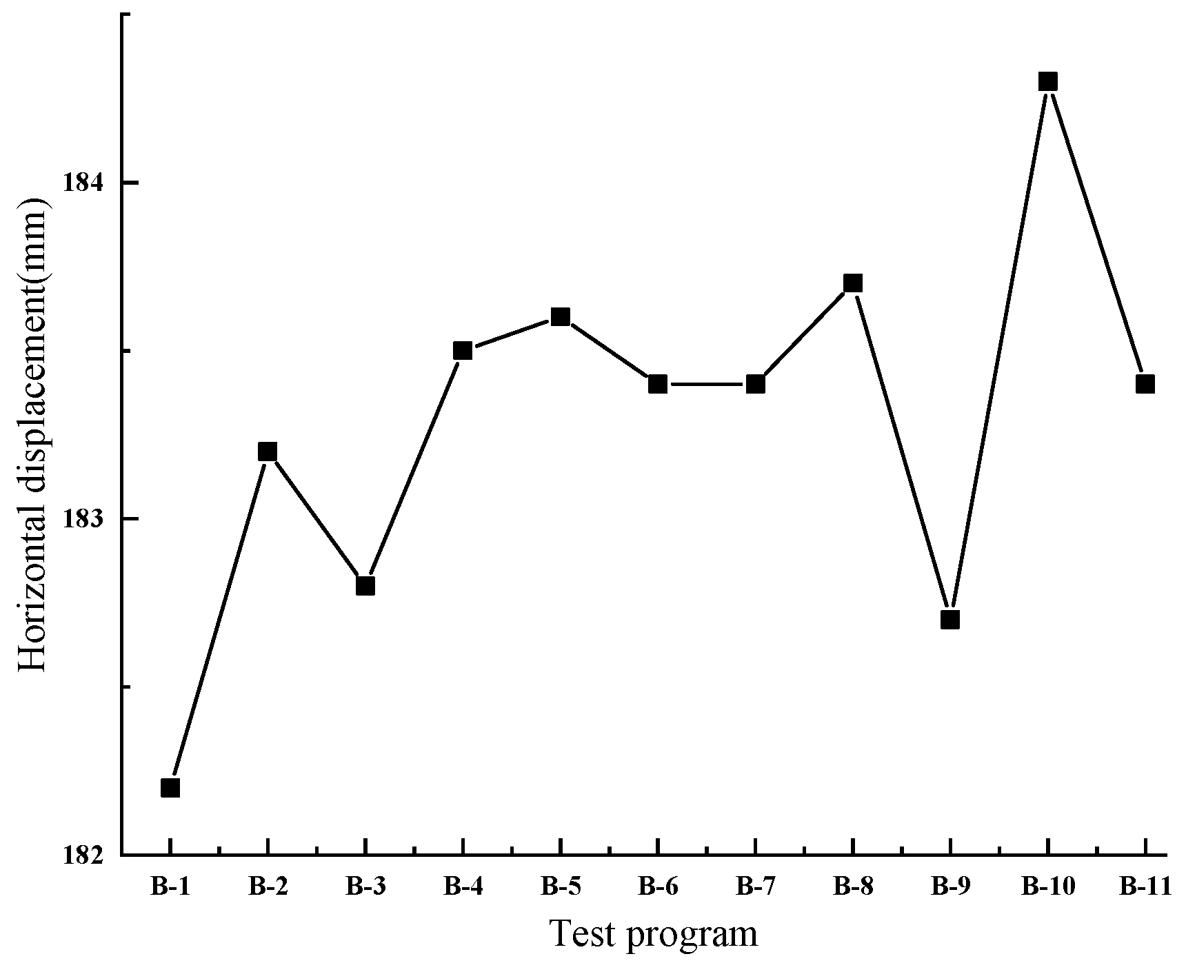
2.2. Effect of the Slope Ratio on the Displacement of Multi-Stage Loess Slopes

In order to further study the effect of the comprehensive slope ratio on slope displacement, when the comprehensive slope ratio is taken as 1:0.83, by changing the slope ratio at all stages, this paper designs 11 groups of single-factor influence tests (see Table 2). The slope height at all stages is 10 m, and the change range of the slope ratio for each stage of each working condition is 0.5–1.5.
The arrangement of slope monitoring points and the required parameter settings of the finite element model in this section are the same as those in Section 2.1 for each working condition, and the distribution of final state horizontal displacement of multi-stage loess slopes under each working condition is shown in Figure 3.
As can be seen from Figure 3, when the comprehensive slope ratio is 1:0.83, the horizontal displacement trend of each condition’s slope surface is basically the same, which shows the phenomenon of increasing and then decreasing along the slope height, and it reaches the maximum at the position of 5 m to 10 m from the slope bottom. The difference in horizontal displacement at the same monitoring point of each working condition’s slope is small, so the change in slope ratio at each stage under seismic action has less influence on the horizontal displacement of the multi-stage loess slope. Figure 4 shows that the horizontal displacements of multi-stage loess side slopes under seismic action change in the range of 182.2–184.3 mm, with a difference of 2.1 mm. Therefore, it is feasible to calculate the displacements of multi-stage side slopes using the composite slope ratio when the composite slope ratio remains unchanged while the slope ratio of all stages is changed.

3. Displacement Calculation of Multi-Stage Homogeneous Loess Slopes Under Seismic Action

As can be seen from Section 2.1 and Section 2.2, a single change in the slope ratio or an increase in the number of slope stages has a small effect on the displacement of the multi-stage loess slope under horizontal seismic action. In order to simplify the calculation, the geometric characteristics of the multi-stage loess slope can be expressed in terms of the comprehensive slope ratio, which is equivalent to a single-stage slope with the same slope ratio for the displacement calculation (see Figure 5).

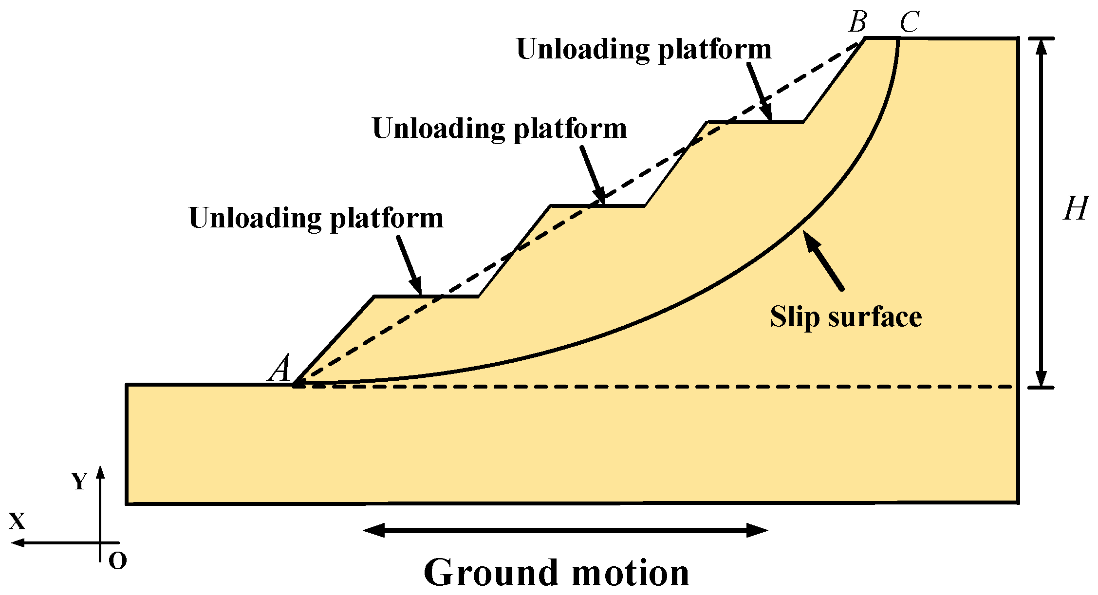
3.1. Basic Assumptions

To simplify the calculation, this paper adopts the slope displacement calculation model under seismic action proposed by ref. [15], as shown in Figure 6. The slope profile is simplified to a right trapezoidal section, and the following assumptions are made:
(1)
The slope soil body is a linear viscoelastic body.
(2)
The motion of the slope is horizontal shear motion under the horizontal seismic action [16].
(3)
It is a two-dimensional plane strain problem.

3.2. Equations of Motion

Under the horizontal seismic action, the slope soil body undergoes horizontal shear motion. u is the horizontal displacement of the slope’s soil, G is the shear modulus of the soil body, ρ is the soil density, c is the viscous damping coefficient, n is the comprehensive slope ratio of the multi-stage slope, M is the length of the slope’s top, and u g is the ground motion input at the bottom boundary of the model. Based on the basic theory of soil dynamics [23], combined with related research results [14,16], the motion equation of the slope under horizontal seismic action is shown as follows:
ρ 2 u t 2 + c u t G ( 2 u y 2 + 1 y n + M u y ) = ρ 2 u g t 2 .

3.3. Boundary Conditions

(1)
Initial conditions [15]:
| u | t = 0 = 0 ,   | u t | t = 0 = 0 .
(2)
Continuous deformation conditions:
  u i ( H H i , t ) = u i + 1 ( H H i , t ) ,
  | G u i y | y = H H i = | G u i + 1 y | y = H H i .

3.4. Displacement Calculation of Slope Soil

Let the solution of Equation (1) be:
u ( y , t ) = Im [ U ( y ) e i ω t ] ,
where u(y, t) is the solution of u in Formula (1), and U(y) is the dynamic displacement amplitude of the soil layer at slope height y.
u g = Im ( U 0 e i ω t ) .
Substituting Formulaes (1), (5) and (6),
2 U ( y ) y 2 + 1 y n + M U ( y ) y i c ω ρ ω 2 G U ( y ) + ρ ω 2 U 0 G = 0 .
Based on the boundary conditions, the expression for the horizontal displacement of the slope soil layer is obtained as follows:
u ( y , t ) = Im [ ( k = 1 n Φ k ( y ) q k ( t ) ) × e i ω t ] .

4. Calculation Validation

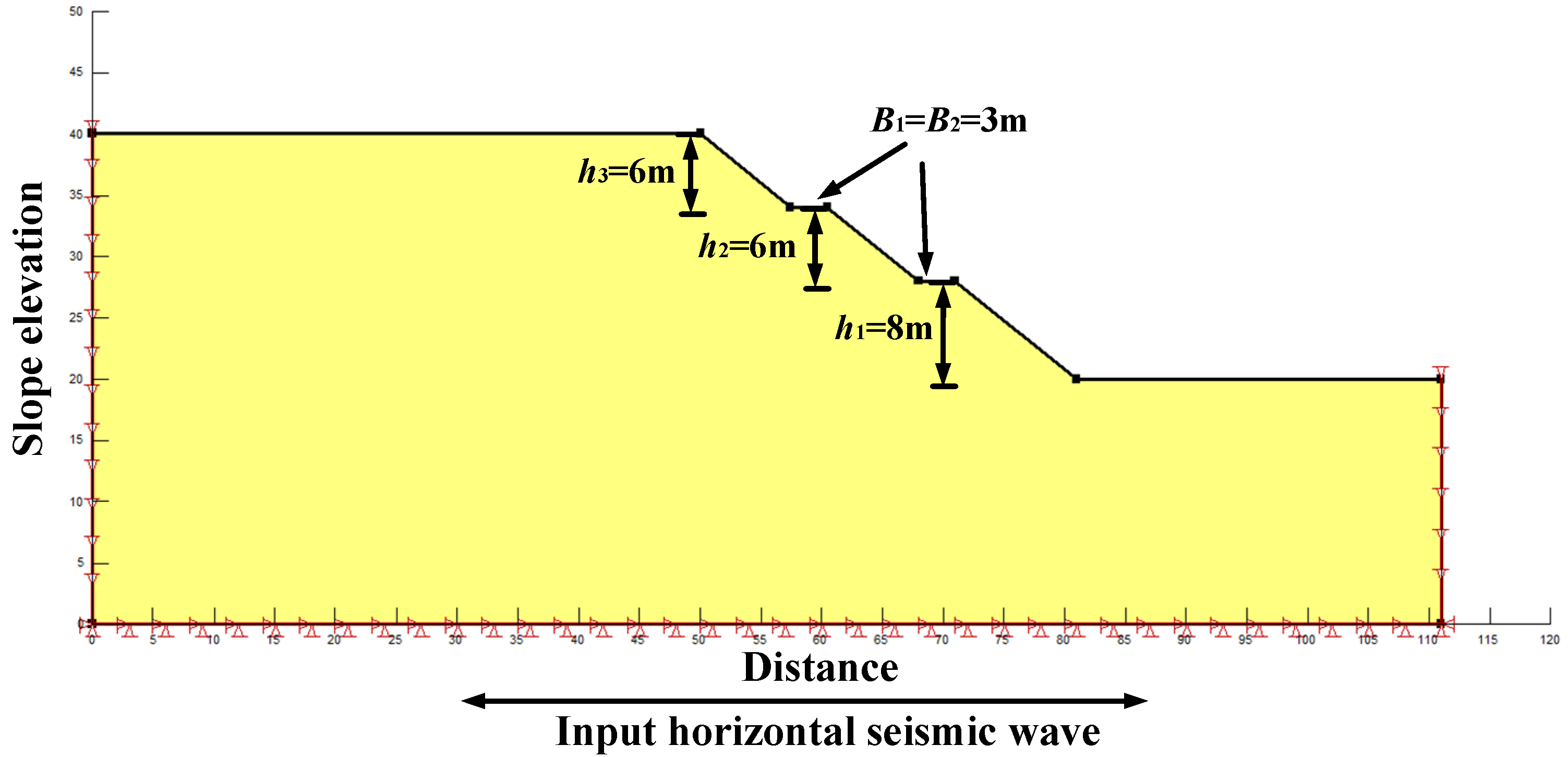
4.1. Calculation Model

It is known that in a three-stage homogeneous loess slope, the slope height of each stage h 1 = 8 m, h 2   = h 3   = 6 m, the slope ratio of each stage i 1 =     i 2   = i 3   = 1:1.25, and the platform width B 1 = B 2 = 3 m. The natural gravity of the soil body γ is 16.8 kN/ m 3 . The Poisson’s ratio   v is 0.3. The horizontal dynamic load is w a v e = λ s i n (2 π t f ). The peak acceleration is 0.2 g, and the seismic frequency is 2.0 Hz. The superior period T s = 0.5 s, and duration t = 10 s. The slope defense intensity is VIII, and the slope grade is II. The physical and mechanical parameters of the multi-stage homogeneous loess slope are shown in Table 3. The seismic wave with a peak acceleration of 0.2 g in the horizontal direction is input at the bottom of the slope, and the acceleration fluctuation of the seismic wave in the first 1s is shown in Figure 7.

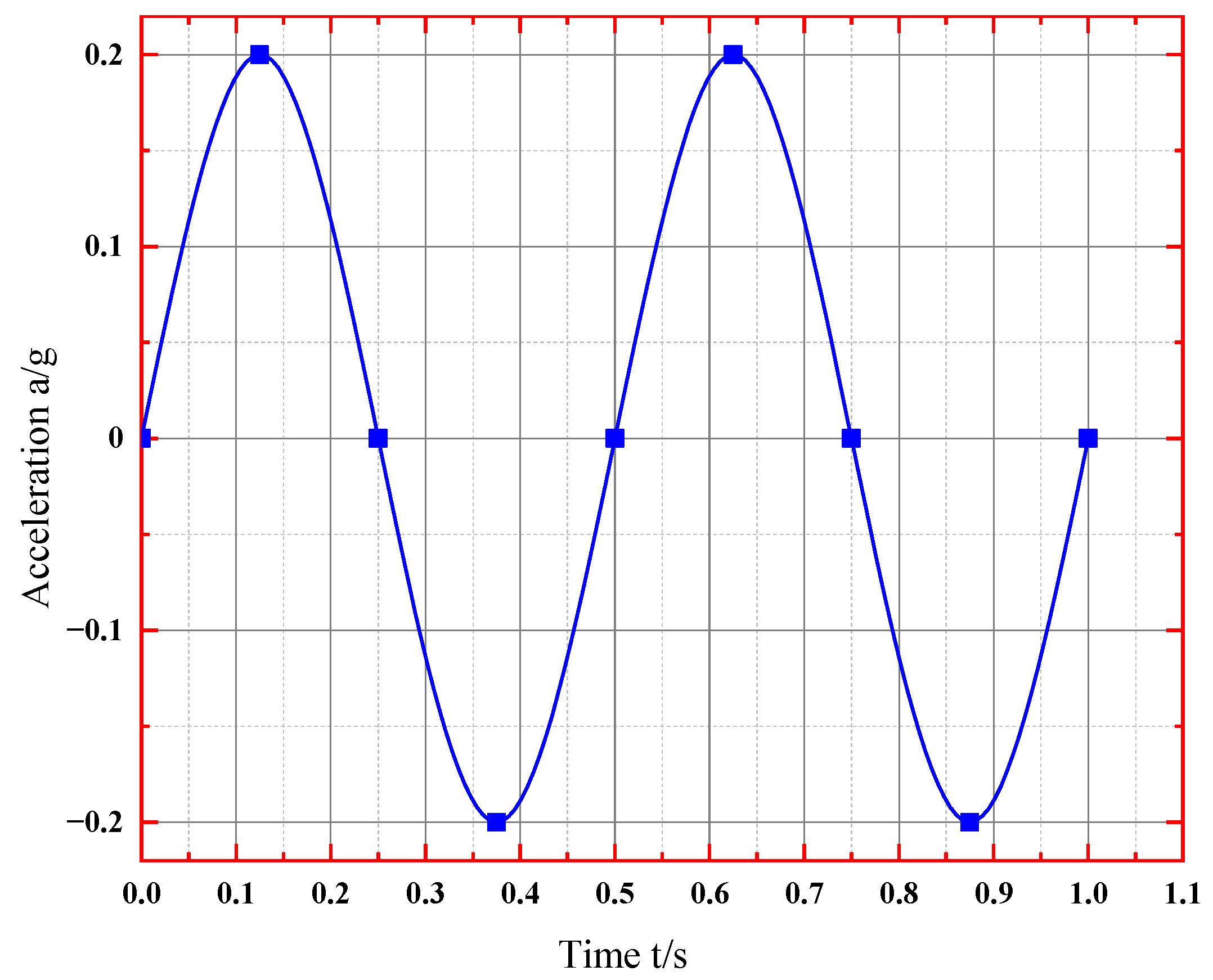
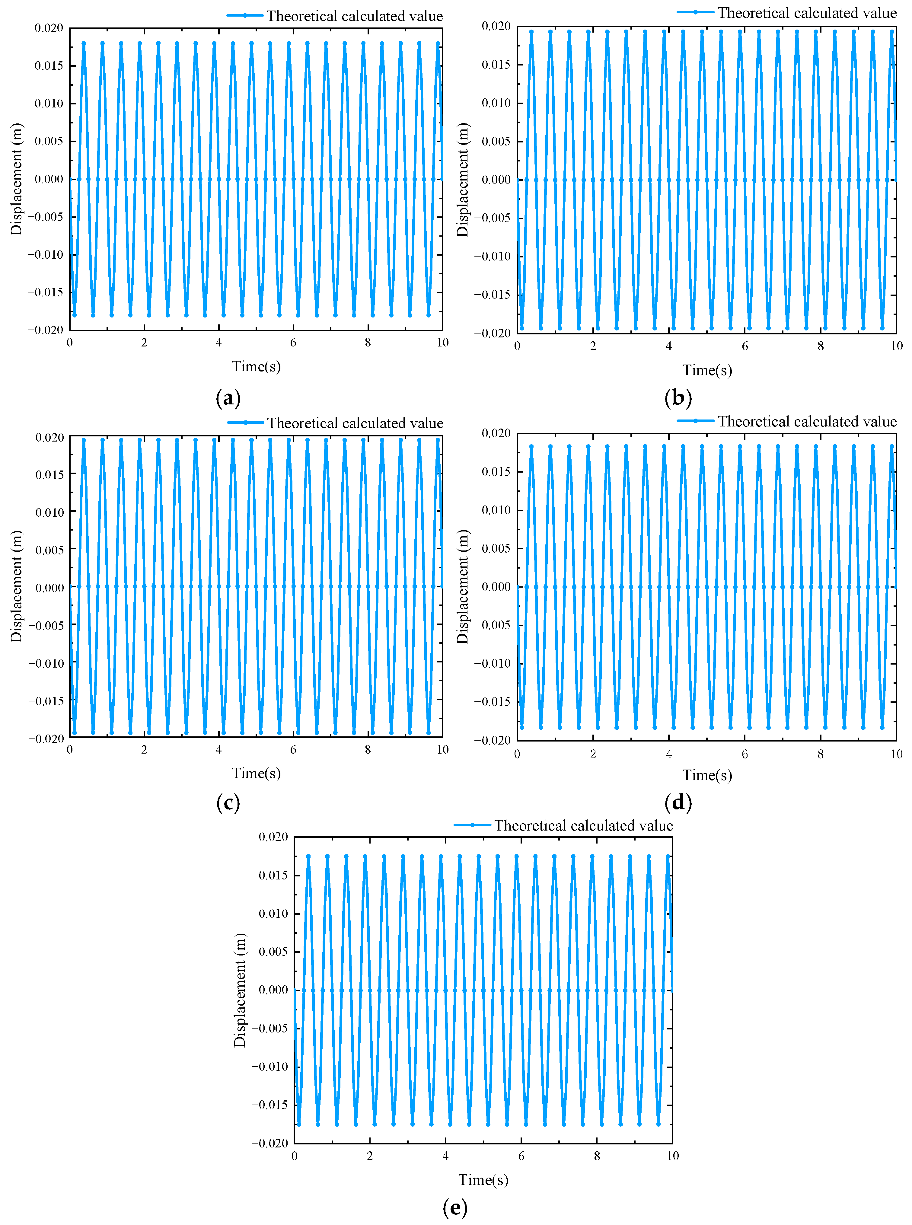
4.2. Theoretical Calculation

The relevant parameters of the multi-stage loess slope under seismic action are substituted into theoretical formulae, and different slope heights are input for displacement calculation. The results are shown in Figure 8.

4.3. Numerical Calculation

In this paper, the finite element software Geo Studio is used to model the multi-stage homogeneous loess slope and perform numerical calculations. As shown in Figure 9, the leading edge of this multi-stage homogeneous loess slope measures 1.5 times the slope height, and the trailing edge measures 2.5 times the slope height. A seismic wave with a peak acceleration of 0.2 g in the horizontal direction is input at the bottom of the slope. The boundary condition of the initial state is that the two ends of the slope bottom are fixed, and the elevation direction is fixed horizontally. The boundary condition in the dynamic stage is that the two ends of the slope bottom are fixed, and the elevation direction is fixed vertically. The numerical calculation results of the displacement time–history curves at different heights of the multi-stage slope are shown in Figure 10.

4.4. Comparative Analysis

A comparison of theoretical and numerical calculation results in this paper is shown in Table 4.
From Table 4, it can be seen that the peak displacement obtained from theoretical and numerical calculations in this paper shows a trend of increasing first and then decreasing along the height direction of the slope. The deviation in the peak displacements of the two methods at the corresponding slope height is not large (approximately 5%). The main reason for the deviation is that this paper adopts a comprehensive slope ratio to simplify the geometrical characteristics of the multi-stage loess slope. From the comparative analysis, it can be seen that the theoretical calculation method of this paper is reasonable.

5. Conclusions

In this paper, the horizontal displacement of a multi-stage homogeneous loess slope is calculated using a theoretical method and numerical simulation method, respectively, and the main conclusions are as follows:
(1)
Based on the basic theory of soil dynamics, this paper introduces the comprehensive slope ratio, takes the damping and deformation of the soil body into full consideration, establishes the displacement calculation model of a multi-stage homogeneous loess slope under seismic action, and provides the analytical expression.
(2)
In this paper, a multi-stage homogeneous loess slope model for each working condition is established using finite element software. It is found that, under the condition of an unchanged comprehensive slope ratio, a single change in the number of slope stages or slope ratio of all stages has a small influence on the horizontal displacement of a multi-stage slope, and the slope horizontal displacements along the direction of the slope height show the phenomenon of increasing first and then decreasing. Therefore, when calculating the horizontal displacement of a multi-stage homogeneous loess slope under seismic action, the geometric characteristics of a multi-stage loess slope can be simplified by adopting the comprehensive slope ratio.
(3)
Comparing the theoretical and numerical calculation results of this paper, it can be seen that the peak displacement of a multi-stage homogeneous loess slope at each height position does not deviate much (5.5%), which indicates that the theoretical calculation method of this paper is reasonable.
(4)
The analytical model could be extended in future work to account for stratified loess, anisotropy, or inhomogeneity, which would enhance the model’s realism and field applicability.

Author Contributions

Conceptualization, J.L. and S.Y.; Methodology, J.L. and S.Y.; Resources, J.L., S.Y., X.C. and B.L.; Data curation, J.L. and N.L.; Writing—review and editing, J.L.; Visualization, J.L. and N.L.; Supervision, X.C. and B.L. All authors have read and agreed to the published version of the manuscript.

Funding

Gansu Provincial Department of Education Young Doctor Support Project (2023QB-048); Gansu Provincial Department of Housing and Urban–Rural Development Science and Technology Research Project (JK2023-15); Gansu Province Science and Technology Plan Project (24JRRA292); Gansu Province Higher Education Teacher Innovation Fund Project (2025B-242); the National Natural Science Foundation of China (52168050).

Data Availability Statement

The data that support the findings of this study are available from the corresponding author upon reasonable request.

Acknowledgments

The authors acknowledge support from the Lanzhou Institute of Technology, Lanzhou University of Technology, Chongqing University, and Shandong University.

Conflicts of Interest

Author Biao Liu was employed by Third Construction Co., Ltd. of China Construction Fifth Engineering Bureau. The remaining authors declare that the research was conducted in the absence of any commercial or financial relationships that could be construed as a potential conflict of interest.

References

  1. Rahangdale, D.; Singh, A.; Adhikary, S. Seismic Fragility Analysis of Finite Slope Considering Pile–Anchor Structure. Indian Geotech. J. 2024, 55, 608–621. [Google Scholar] [CrossRef]
  2. Christoph, C.; Machaček, J.; Prada-Sarmiento, L.F.; Staubach, P.; Wichtmann, T. Strain-dependent slope stability for earthquake loading. Comput. Geotech. 2022, 152, 105048. [Google Scholar]
  3. Wang, J.; Shahani, N.M.; Zheng, X.; Hongwei, J.; Wei, X. Machine learning-based analyzing earthquake-induced slope displacement. PLoS ONE 2025, 20, e0314977. [Google Scholar] [CrossRef] [PubMed]
  4. Zhang, F.; Lin, L.; Shu, S.; Yang, S.; Gao, Y. Static-dynamic stability analysis and spatial effect study of turning convex slope. J. Geotech. Eng. 2022, 44, 1558–1566. [Google Scholar]
  5. Wang, J.; Xia, Y.; Wang, Z. Calculation method of post-seismic displacement of slopes considering the softening effect of slip surface strain. J. Comput. Mech. 2025, 41, 1029–1036. [Google Scholar]
  6. Ji, J.; Lin, Z.; Li, S.; Song, J.; Du, S. Coupled Newmark seismic displacement analysis of cohesive soil slopes considering nonlinear soil dynamics and post-slip geometry changes. Comput. Geotech. 2024, 174, 106628. [Google Scholar] [CrossRef]
  7. Yu, J.; Huang, X.; Chen, Z.; Wang, L.; Ruan, B.; Pan, Q. Three-dimensional upper limit analysis of post-seismic displacement of soil nail-supported slopes based on Newmark method. J. Railw. Sci. Eng. 2025, 22, 161–171. [Google Scholar]
  8. Rao, P.; Tong, L.; Shi, Y. Seismic stability analysis of sliding pile reinforced slopes based on the proposed dynamic method. World Earthq. Eng. 2020, 36, 189–196. [Google Scholar]
  9. Jiang, Q.; Deng, Y.; Yang, N.; Sun, L.; Mu, H. Stability analysis of a proposed dynamic seismic slope based on the strict bar division method. J. Earthq. Eng. 2023, 45, 716–723. [Google Scholar]
  10. Santo, S.A.; Hossain, A.S.M.F.; Fariha, A.S.; Haque, E.; Ansary, M.A. Assessment of seismic slope stability of Rangamati Hill Tracts, Bangladesh. Discov. Geosci. 2024, 2, 1. [Google Scholar] [CrossRef]
  11. Zheng, T.; Xiao, S. Comparison of centralised and decentralised modes of seismic active earth pressure proposed static method for retaining walls. Railw. Stand. Des. 2022, 66, 20–26. [Google Scholar]
  12. Nayek, P.S.; Gade, M. Artificial neural network-based fully data-driven models for prediction of Newmark sliding displacement of slopes. Neural Comput. Appl. 2022, 34, 9191–9203. [Google Scholar] [CrossRef]
  13. Takaji, K. Spring-Supported Newmark Model Calculating Earthquake-Induced Slope Displacement. J. Geotech. Geoenviron. Eng. 2024, 150, 04024024. [Google Scholar]
  14. Dong, J.; Zhu, Y.; Ma, W. Research on the dynamic calculation method of frame prestressed anchor slope support structure. Eng. Mech. 2013, 30, 250–258+264. [Google Scholar]
  15. Wang, L.; Pu, X.; Wu, Z.; Xu, S.H.; Liu, K. Shaking table experimental study on dynamic response of loess slopes under coupled earthquake and rainfall. J. Geotech. Eng. 2018, 40, 1287–1293. [Google Scholar]
  16. Wei, R.; Ding, G.; Peng, W. Dynamic response analysis of sliding pile supported slopes under earthquake. Urban Surv. 2020, 5, 203–208. [Google Scholar]
  17. Gibson, D.M.; Wartman, P.J.; MacLaughlin, M.M.; Keefer, D.K. Pseudo-static failure modes and yield accelerations in rock slopes. Int. J. Rock Mech. Min. Sci. 2018, 102, 1–14. [Google Scholar] [CrossRef]
  18. Mathews, N.; Leshchinsky, B.A.; Olsen, M.J.; Klar, A. Spatial distribution of yield accelerations and permanent displacements: A diag-nostic tool for assessing seismic slope stability. Soil Dyn. Earthq. Eng. 2019, 126, 105811. [Google Scholar] [CrossRef]
  19. Mostafaei, H.; Morteza, S.G.; Mohsen, G. A comparative study between pseudo-static and dynamic analyses on rock wedge stability of an arch dam. Civ. Eng. J. 2018, 4, 179–187. [Google Scholar] [CrossRef]
  20. Zhang, R.; Ye, S.; Tao, H. Stability analysis of multistage homogeneous loess slopes by improved limit equilibrium method. Rock Soil Mech. 2021, 42, 813–825. [Google Scholar]
  21. Wang, Y. Calculation of Permanent Displacement and Dynamic Response Analysis of Multi-Stage Loess Slopes Under Seismic Action. Master’s Thesis, Lanzhou University of Technology, Lanzhou, China, 2022. [Google Scholar]
  22. Zhang, R. Stability Analysis Of multi-Stage Loess Slopes Under Seismic Action. Master’s Thesis, Lanzhou University of Technology, Lanzhou, China, 2021. [Google Scholar]
  23. Xie, D. Soil Dynamics; Xi’an Jiaotong University Press: Xi’an, China, 1998; pp. 251–262. [Google Scholar]
Figure 1. Working condition A−3 monitoring point layout.
Buildings 15 01484 g001
Figure 2. The distribution of final state horizontal displacement at each monitoring point under different comprehensive slope ratios. (a) The slope ratio of 1:0.75; (b) the slope ratio of 1:1.0; (c) the slope ratio of 1:1.25; (d) the slope ratio of 1:1.5.
Buildings 15 01484 g002
Figure 3. Final state horizontal displacement distribution of monitoring points on the slope surface for each working condition.
Buildings 15 01484 g003
Figure 4. Final state horizontal displacement under the change in each slope ratio at the same comprehensive slope ratio.
Buildings 15 01484 g004
Figure 5. Multi-stage loess slope sliding system under seismic action.
Buildings 15 01484 g005
Figure 6. Simplified displacement calculation model of a multi-stage loess slope under seismic action: (a) simplified displacement calculation model of the slope; (b) force model for the thin-layer element of slope soil.
Buildings 15 01484 g006
Figure 7. Calculation model horizontal acceleration curve with time.
Buildings 15 01484 g007
Figure 8. Theoretically calculated displacement time−history curves at different slope heights: (a) displacement time−history curve of the slope at y = 0 m; (b) displacement time−history curve of the slope at y = 5 m; (c) displacement time−history curve of the slope at y = 10 m; (d) displacement time−history curve of the slope at y = 15 m; (e) displacement time−history curve of the slope at y = 20 m.
Buildings 15 01484 g008
Figure 9. Analytical model of a multi-stage loess slope under seismic action.
Buildings 15 01484 g009
Figure 10. Numerically calculated displacement time−history curves at different slope heights: (a) displacement time−history curve of the slope at y = 0 m; (b) displacement time−history curve of the slope at y = 5 m; (c) displacement time−history curve of the slope at y = 10 m; (d) displacement time−history curve of the slope at y = 15 m; (e) displacement time−history curve of the slope at y = 20 m.
Buildings 15 01484 g010
Table 1. Table of one-factor test conditions for changing slope stages.
Working ConditionSlope StageComprehensive Slope RatioWorking ConditionSlope StageComprehensive Slope Ratio
A111:0.75A-911:1.25
A-22A-102
A-33A-113
A-44A-124
A-511:1.0A-1311:1.5
A-62A-142
A-73A-153
A-84A-164
Table 2. Table of one-factor test conditions for changing the slope ratio.
Working ConditionSlope Ratio of
Each Stage
Working ConditionSlope Ratio of
Each Stage
B-11:1.0 1:1.0 1:1.0B-71:0.7 1:1.3 1:1.0
B-21:0.9 1:1.0 1:1.1B-81:0.6 1:1.0 1:1.4
B-31:0.9 1:1.1 1:1.0B-91:0.6 1:1.4 1:1.0
B-41:0.8 1:1.0 1:1.2B-101:0.5 1:1.0 1:1.5
B-51:0.8 1:1.2 1:1.0B-111:0.5 1:1.5 1:1.0
B-61:0.7 1:1.0 1:1.3//
Table 3. Physical and mechanical parameters of slope soil.
ParameterCohesion/(kPa)Internal Friction Angle/(°)Damping Coefficient/(kN·s/m)Shear Modulus
G/Mpa
Unit Weight of Soil γ/(kN/m3)
Value1530107.716.8
Table 4. Peak displacement at different slope heights of the multi-stage loess slope under seismic action.
Slope Height/mPeak Displacement/mm
Theoretical CalculationNumerical Simulation Calculation
018.018.9
519.319.8
1019.419.6
1518.518.6
2017.517.9
Disclaimer/Publisher’s Note: The statements, opinions and data contained in all publications are solely those of the individual author(s) and contributor(s) and not of MDPI and/or the editor(s). MDPI and/or the editor(s) disclaim responsibility for any injury to people or property resulting from any ideas, methods, instructions or products referred to in the content.

