Abstract
The long-term safety of concrete shaft walls in deep mines faces severe challenges from the coupled effects of stress, chemical erosion, and dynamic disturbances. This study conducted coupled loading and sulfate erosion tests on concrete and investigated its dynamic response using drop-weight impact tests. The failure modes, impact force time-history curves, and strain time-history curves of concrete under different erosion ages and load levels were analyzed. The SEM observations revealed the microstructure of the concrete. Results indicate that increasing drop height exacerbates specimen failure and elevates peak impact force and strain, while simultaneously shortening the impact duration. Compared to SL20, SL40 exhibited lower peak impact force and higher peak strain under long-term combined loading and sulfate erosion. This reveals that larger loads accelerate internal damage within concrete under erosive conditions. This study provides theoretical and experimental bases for the long-term safety and impact resistance of well wall concrete.
1. Introduction
As shallow-level resources on Earth become increasingly depleted, the depth of mineral resource extraction has increased to accommodate the demands of societal development, with the extraction depth in several mining areas now exceeding 1000 m [1,2]. The geological environment of deep strata exhibits significant differences compared to that of shallow strata. Complex environmental factors, such as elevated geological stress, high temperature, and increased water pressure, present considerable challenges for deep-level engineering construction [3,4]. Given that shafts serve as a key access channel for deep-level resource extraction [5], their structural functionality and safety must be assured throughout the entire service life of the mine. Therefore, high-strength concrete, known for its exceptional performance, is extensively applied in the design of shaft wall structure [6]. Due to the influence of high-intensity mining disturbances at depth, concrete is prone to instantaneous impacts resulting from rock bursts. Under dynamic loads of sufficient amplitude, concrete may fracture, fail, or shatter [7]. Therefore, it is imperative to thoroughly consider the effects of dynamic loads in the design of shaft wall concrete, as this is critical for ensuring the structural safety and stability of the key access channels of the mine.
In recent years, the effects of dynamic loads on concrete have been extensively investigated. Guo Y B et al. [8] reported that the compressive strength of concrete is enhanced at a higher strain rate, showing a gradual enhancement of strength up to a specific transition point, beyond which there is a marked rise in strength. Additionally, studies suggest that, at strain rates below this transition point, the variation in strength is primarily influenced by viscosity effects associated with the moisture content within the concrete [9]. In contrast, when strain rates exceed the transition point, the dominant factor influencing the strength appears to be the radial inertial effect [10]. Xu C et al. [11] explored the failure mechanism of concrete during impact loading and revealed that, at lower strain rates, cracks initiate within the concrete matrix while the coarse aggregates remain largely intact. However, as the strain rate increases, cracks tend to propagate along shorter paths within the concrete, leading to the fracturing of the more robust coarse aggregates. Furthermore, Chen X et al. [12] investigated the dynamic splitting deformation failure characteristics of C60 and C80 concrete; their findings indicated that, under high strain rates, concrete specimens with high strength experience accelerated damage progression, increased crack propagation, and more pronounced brittle damage. Dancygier A N et al. [13,14] demonstrated that concrete with high strength offers superior resistance to impact loads compared to that with normal strength.
Shaft concrete walls are exposed to complex underground environments where corrosive ions are commonly present in the external surroundings of vertical shaft walls [15]. These corrosive ions penetrate the concrete through diffusion driven by concentration gradients, triggering chemical corrosion. Among these, sulfate attack is the most prevalent and damaging form of such corrosion [16,17]. Sulfate ions infiltrate the concrete and react with hydration products chemically, forming corrosion products such as calcium aluminate hydrate and gypsum [18]. The effects of these corrosion products on concrete are dual in nature [19]. During the initial stages of corrosion, they may densify the matrix by pore-filling, thereby reinforcing the mechanical properties of concrete. However, as the concrete ages, water absorption and expansion of these products lead to increased internal pressure and pore coarsening, leading to a significant deterioration in concrete performance [20,21]. Consequently, the effects of dynamic loads on corroded concrete must be considered and evaluated carefully. Xia W et al. [22] found that higher loading rates amplify the impact of sulfate attack on peak strain. Liu T et al. [23] reported that sulfate attack increases the strain rate sensitivity of concrete. Wei J et al. [24] and Liu P et al. [25] observed that, after sulfate attack, the concrete develops more microcracks and defects. When subjected to impact, these damages absorb the impact energy, enhancing the energy dissipation. Ji Z et al. [26] explored the impact resistance of sulfate-corroded concrete and observed that, with an increasing number of dry–wet cycles, the dynamic compressive strength initially increased and subsequently declined, whereas the peak strain exhibited an opposite trend, decreasing first and then increasing. Liu R et al. [27,28] examined dynamic mechanical properties of eroded concrete and demonstrated that both compressive strength and elastic modulus become more sensitive to strain rate after erosion, while the deformation decreases in concrete deteriorate with higher sulfate ion concentrations.
Since the wellbore concrete is located underground, it is also subjected to loads generated by groundwater within the overlying aquifer and surrounding rock [29]. Research [30,31] has shown that, at lower loading levels, some pores are closed within the concrete, which delays the penetration of sulfate ions; conversely, at higher loading levels, microcracks form within the concrete, accelerating the penetration of sulfate ions. Additionally, Yang L [32] pointed out that, unlike sulfate attack alone, the combined action of mechanical loading and sulfate erosion produces a coupled damaging effect on concrete. Blikharskyy Y et al. [33] investigated the combined effects of erosion and loading on concrete, concluding that residual strength is significantly influenced by applied load levels and environmental conditions. Guan B et al. [34] developed a damage function for concrete subjected to combined drying–wetting cycles and alternating loading based on variations in concrete ultrasonic velocity. Ji Z et al. [26] indicated that structural defects and internal cracks generated within concrete severely impair its dynamic response capability under high-strain-rate conditions. Therefore, it is crucial to consider the impact of combined erosion and loading on concrete’s impact resistance to ensure mine safety. Currently, scholars have conducted in-depth research on the mechanical properties of concrete after the coupled effects of loading and erosion, but have not considered the impact of these coupled effects on the dynamic load response of concrete. In this study, a drop hammer impact device was employed to conduct drop hammer impact tests on concrete specimens subjected to the combined action of loading and sulfate erosion. This study observed the fracture patterns of concrete after impact, investigated trends in the time-history curves of impact force and strain, analyzed peak impact force and strain values, and examined the microstructure of concrete using scanning electron microscopy (SEM) to provide microscopic support for macroscopic mechanical properties. This study provides a theoretical basis for impact resistance design and safety assessment of concrete under coupled loading and erosion conditions through impact testing and microscopic analysis of concrete subjected to coupled loading and erosion.
2. Materials and Methods
2.1. Test Material
The concrete was prepared using P.O42.5 ordinary Portland cement (Jidong Qixin Cement Co., Ltd., Tangshan, China), with performance parameters listed in Table 1. The coarse aggregate consisted of continuously graded crushed stone with particle sizes ranging from 5 to 20 mm; the fine aggregate was manufactured sand having a fineness modulus of 2.73. Grade I fly ash was incorporated, exhibiting a density of 2.1 g/cm3 and a specific surface area (SSA) of 420 m2/kg. Mineral powder (a density of 3.1 g/cm3 and an SSA of 429 m2/kg) and silica fume (a density of 2.23 g/cm3 and an SSA of 22 m2/g) were also used. Anhydrous sodium sulfate, supplied by Hongze Dayang Salt Chemical Co., Ltd. (Huaian, China), was employed as the corrosive agent, and its properties are provided in Table 2. A high-performance polycarboxylate superplasticizer with 50% solid content was used as the water reducer, and tap water served as the mixing water.

Table 1.
Parameters of cement-related performance indicators.
Table 2.
Performance indicators of anhydrous sodium sulfate.
2.2. Preparation of Test Specimens
The used concrete had a strength grade of C70, and the test specimens were 100 mm × 100 mm × 100 mm cubic specimens. Vibration table compaction was used, and after 24 h, the specimens were demolded and transferred to a standard curing tank. After the curing period, the cube compressive strength was determined. The mix design and compressive strength are outlined in Table 3.
Table 3.
Mix design and compressive strength.
2.3. Experimental Methods
After initial curing, a continuous load was applied to the concrete test specimens using a loading device at load ratios of 20% and 40% of the 28-day compressive strength. The loaded specimens were then immersed in a 10% sodium sulfate solution for 30, 180, and 240 days, with the solution refreshed every 30 days. A control group was immersed in distilled water under the same conditions. The impact tests were conducted using a drop hammer, as shown in Figure 1. The hammer, with a mass of 70 kg and a spherical impact head, was dropped from 0.4, 0.6, and 0.8 m. Strain gauges were mounted symmetrically on the front and rear surfaces of the specimens to capture dynamic strain response during impact. The configuration of the strain gauge is shown in Figure 1b.
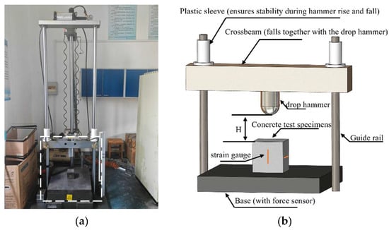
Figure 1.
Drop-weight impact tester. (a) site plan of test facility; (b) schematic diagram of test apparatus.
2.4. Load Application Method
In this experiment, a self-made continuous loading device was employed to apply compressive loads to the concrete specimens. The desired load ratios were achieved by adjusting the torque applied to the nut using a torque wrench. The loading diagram is provided in Figure 2.
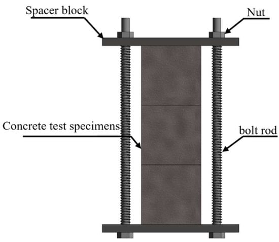
Figure 2.
Loading device.
2.5. Test Piece Number
The following coding system was adopted to designate the specimens: W (plain water group specimens) and SL20 and SL40 (specimens with a loading ratio of 20% and 40% and immersed in a sulfate solution, respectively). The impact energy levels were indicated by 0.4, 0.6, and 0.8, corresponding to drop-weight heights of 0.4, 0.6, and 0.8 m, respectively. The corrosion ages were presented by 30, 180, and 240, referring to exposure periods 30, 180, and 240 days, respectively. For example, the label 30-W-0.4 indicates a fresh water group specimen with a corrosion age of 30 days subjected to a drop-weight impact with a height of 0.4 m. Two specimens were prepared for each case, totaling 54 specimens.
3. Results
3.1. Fracture Morphology Analysis
Figure 3 illustrates the impact-induced failure patterns of three groups of concrete specimens (W, SL20, and SL40) under three different drop heights. As depicted, all concrete specimens exhibited splitting failure across different drop heights, demonstrating distinct brittle characteristics. At the lowest drop height selected in this study (0.4 m), the failure of the specimens was primarily characterized by crack initiation and propagation. Most cracks developed along the weak zones within the concrete matrix, resulting in failure along two to three major cracks. Meanwhile, there were relatively few damaged aggregates on the fracture surfaces. As the drop height increases, the number of fragments gradually increases, while their size decreases, with a significant increase in small fragments. The number of damaged aggregates on the fracture surface also increases markedly, indicating that the fragmentation behavior became more pronounced. This shift in failure mode can be attributed to the fact that the duration of the impact force decreases as the drop height increases, leaving the specimen insufficient time to accumulate energy. Stress increases rapidly within a short time, and before cracks can propagate along paths of lower resistance, stress levels rise to a point where they can destroy higher-strength aggregate particles. As a result, there is a significant increase in the number of damaged aggregates at the failure interface, and the impact energy is absorbed by numerous microcracks and weak interfaces, leading to widespread microcracking and the generation of fine fragments.
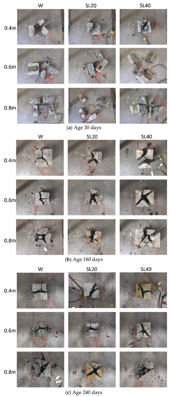
Figure 3.
Destruction pattern.
3.2. Impact Force and Strain–Time Curve Analysis
Figure 4, Figure 5 and Figure 6 present the impact force versus strain time-history curves for the W, SL20, and SL40 specimens under varying drop heights. It is evident that the slope of the time-history curves becomes steeper and the duration of the impact force decreases with increasing drop height across all specimen groups and ages.
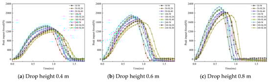
Figure 4.
Impact force time-history curve.
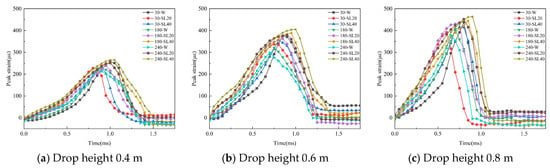
Figure 5.
Vertical strain-history curve.
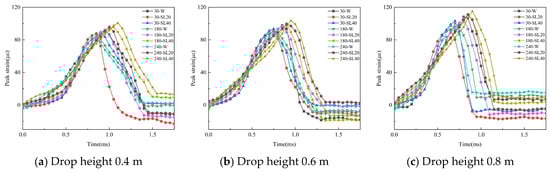
Figure 6.
Transverse strain-history curve.
At identical drop heights, the W specimens demonstrate an increase in time-history curve slope and a reduction in impact force duration as the curing period extends. Conversely, for both the SL20 and SL40 specimens, the slope decreases and the impact force duration lengthens as the erosion duration increases. After 30 days of erosion, the order of impact force duration among all three groups exhibited W > SL40 > SL20. However, when the erosion duration reaches 180 and 240 days, this order changes to SL40 > SL20 > W. This is because, for W specimens, as the curing age increases, concrete undergoes continuous hydration, leading to enhanced strength. However, under impact loading, the concrete becomes more prone to brittle failure. Consequently, the peak impact force increases while the peak vertical and transverse strains decrease, resulting in a progressively shorter duration of impact force application. For SL20 and SL40 specimens, erosion and loading induce internal damage within the concrete. This damage effectively absorbs impact energy during loading, resulting in reduced peak impact force and increased peak vertical and transverse strains. Consequently, the duration of impact force application gradually increases, with a more pronounced improvement observed under 40% loading.
3.3. The Effect of Drop Height on Peak Impact Force and Strain
Figure 7, Figure 8 and Figure 9 show the variations in the peak impact force and peak strain with respect to drop height for the W, SL20, and SL40 test specimens at the same corrosion ages.
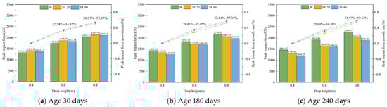
Figure 7.
Variation in peak impact force of concrete test specimens at different drop heights.
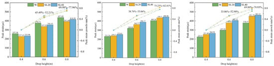
Figure 8.
Variation in vertical peak strain in concrete specimens at different drop heights.
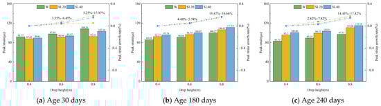
Figure 9.
Variation in lateral peak strain in concrete specimens at different drop heights.
As observed, as the drop height increased, both the peak impact force and peak strain of the W, SL20, and SL40 specimens gradually increased, and the rate of increase in them accelerated with higher impact energy, though the growth rate itself diminished. At 30 days, the differences in the growth rate of peak impact force among the W, SL20, and SL40 specimens remained within 3.3%. By 180 and 240 days, the differences increased to 6.44% and 8.76%, respectively, when the drop height was 0.6 m, but reduced to approximately 4.51% and 5.19% at 0.8 m. A similar trend was observed for the growth rate of peak impact force: At 180 and 240 days, when the drop hammer height is 0.6 m, the vertical peak strain rate difference between SL20 and SL40 specimens and W specimens is most pronounced, at 14.3% and 19.84%, respectively. When the drop height was 0.8 m, the differences decreased to 7.16% and 10.13%, respectively. This behavior can be explained as follows: under lower drop heights, the impact force acts for a relatively long time, which allows the impact energy primarily dissipated through the initiation and propagation of microcracks at the interface between the mortar and aggregate. When the drop heights are high, the duration of the impact force gradually shortens, causing the cracks to propagate along shorter paths, leading to the fracture and failure of the stronger coarse aggregates. The impact energy is then primarily dissipated through the failure of the coarse aggregate, which diminishes the combined effects of erosion and loading on the concrete.
The vertical and lateral strain behavior of concrete exhibits significant differences. For the lateral strain of concrete, at 30 days, the differences in peak transverse strain between W, SL20, and SL40 specimens ranged from 2.9% to 12.72%. As the curing period reached 180 days and 240 days, the differences narrowed to 1.26%, 1.19%, 5%, and 2.99%, respectively. Except for an isolated anomaly in the growth rate of SL20 at 30 days and a drop height of 0.8 m, the intra-group differences in peak lateral strain for all three specimen groups remained at low levels across varying drop heights. Notably, the peak lateral strain of W specimens consistently exceeded that of SL20 and SL40 specimens. This indicates that the transverse peak strain of concrete is primarily influenced by the concrete material itself, while erosion and loading effects have relatively limited impacts. For the vertical strain of concrete, unlike the transverse strain, at the same ages, as the drop-weight height increased, the growth rates of peak strain of both SL20 and SL40 specimens were greater than those of the W specimen. This is because erosion and loading may cause microcracks and defects of the concrete, which allow greater deformation under impact. At 30 days, the vertical peak strain of SL20 and SL40 specimens is greater than that of W specimens, which is mainly due to the erosion-induced increase in strain sensitivity [23], and this increased the vertical peak strain of the SL20 and SL40 specimens.
3.4. Effects of Age on Peak Impact Force and Strain
Under identical drop heights, the variations in peak impact force and strain with age for the W, SL20, and SL40 test specimens are illustrated in Figure 10, Figure 11 and Figure 12.
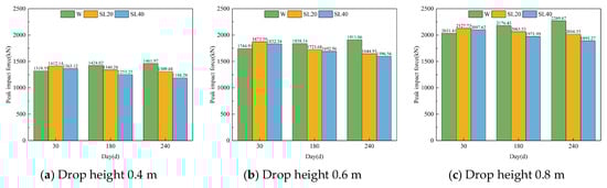
Figure 10.
Changes in peak impact force of concrete specimens at different ages.
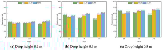
Figure 11.
Variation in vertical peak strain in concrete specimens at different ages.
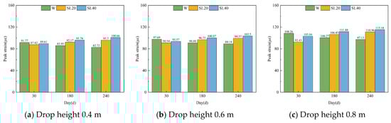
Figure 12.
Variation in lateral peak strain in concrete specimens at different ages.
As observed, with increasing age from 30 to 180 and 240 days, the W specimens exhibited a rise in peak impact force accompanied by a reduction in peak strain. In contrast, the SL20 and SL40 specimens showed a gradual decrease in peak impact force and an increase in peak strain over the same period. This divergence in behavior may have stemmed from the ongoing hydration of the W specimens, which enhances concrete strength but reduces material plasticity with age. Conversely, in the SL20 and SL40 specimens, the combined effects of sulfate erosion and sustained mechanical loading progressively and adversely influence the stability of the internal structure of the concrete, weakening the impact load-bearing capacity and increasing the strain.
At 30 days of age, Compared with the W specimen, the peak impact forces of SL20 and SL40 specimens at drop heights of 0.4 m, 0.6 m, and 0.8 m increased by 7.02% and 3.3%, 7.37% and 5.01%, and 4.74% and 3.26%, respectively; the peak vertical strains decreased by 11.7% and 9.16%, 9.99% and 4.96%, and 10.55% and 4.90%, respectively; while the lateral strains decreased by 4.3% and 2.35%, 6.91% and 4.22%, and 14.62% and 4.71%, respectively. The peak impact force of the three test specimens at varying drop heights ranked as SL20 > SL40 > W, while the peak strain followed the order of W > SL40 > SL20. Compared with the clear water group, concrete under the coupled action of erosion and loading showed increased peak impact force but decreased peak strain. This is because, in an erosive environment, sulfate ions (SO42−) penetrate the interior of the concrete, which stimulates further hydration of unhydrated cement particles and reacts with Ca2+ to generate erosion products that fill and densify microcracks within the concrete matrix. The SEM results regarding microstructure of concrete, displayed in Figure 13a,b, showed that the main erosion products observed were needle-shaped calcium aluminate crystals. Under a 20% load level, microcracks inside the concrete experienced little changes, and some of them even closed [31], inhibiting the intrusion of SO42−. A small amount of SO42− diffuses into the concrete interior through a concentration gradient, producing corrosion products to fill the pores within the concrete, thereby increasing the peak impact force [26] while reducing the peak strain. In contrast, when the load is 40%, the SEM imaging (Figure 13c) revealed microcracks within the concrete. The 40% load caused microcracks to form within the concrete, accelerating the penetration of SO42− into the concrete. In this case, due to the short erosion period, the crack propagation was greater than the pore-filling effect of erosion products on the microcracks. As a result, the density of SL40 specimens was lower than that of SL20 specimens, leading to a decrease in peak impact force but an increase in peak strain.
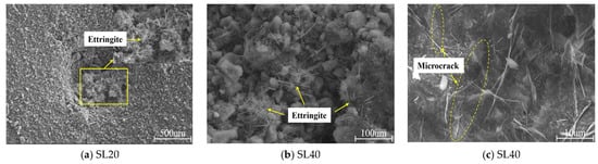
Figure 13.
SEM scanning electron microscope images.
At the age of 180 d, compared with the W specimen, the peak impact forces of SL20 and SL40 specimens at drop heights of 0.4 m, 0.6 m, and 0.8 m decreased by 5.88% and 11.99%, 6.23% and 7.92%, and 5.19% and 9.39%, respectively; the peak vertical strains increased by 3.49% and 9.68%, 13.05% and 20.97%, and 7.71% and 9.68%, respectively; and the lateral strains increased by 7.24% and 11.44%, 6.46% and 10.11%, and 6.14% and 11.14%, respectively. At the age of 240 d, compared with the W specimen, the peak impact forces of SL20 and SL40 specimens at drop heights of 0.4 m, 0.6 m, and 0.8 m decreased by 10.42% and 18.72%, 13.96% and 16.49%, and 11.15% and 16.67%, respectively; the peak vertical strains increased by 12.14% and 18.35%, 27.18% and 35.99%, and 19.34% and 22.39%, respectively; and the lateral strains increased by 15.69% and 21.69%, 11.41% and 16.04%, and 14.24% and 18.58%, respectively. At 180 and 240 days of age, the peak impact force across the three groups of test specimens at different drop heights followed the order of W > SL20 > SL40, while the peak strain followed the order of SL40 > SL20 > W. Compared with the clean water group, concrete subjected to the coupled action of erosion and loading had decreased peak impact force and increased strain. This behavior results from the water absorption and expansion of erosion products over time, which generates new microcracks within the concrete [22], providing new transmission pathways for SO42− to penetrate the concrete, thus facilitating their further penetration. The newly formed SO42− consumes Ca2+ from the pore solution to form additional erosion products. Since the Ca2+ supplied by the ongoing hydration of cement particles becomes insufficient to compensate for the consumption of Ca2+ by SO42− in the formation of erosion products, the Ca2+ concentration in the pore solution decreases. To maintain the Ca2+ equilibrium, the C-S-H gel decomposes to release Ca2+, undermining the stability of the cementitious matrix and reducing the overall strength of concrete. As a result, concrete strength decreases, the peak impact force declines, and the strain increases. The ratio of load to concrete strength changes. Due to the relatively short erosion age and low water–cement ratio of the concrete [35], the load-to-concrete strength ratio undergoes only minor changes. Under a 20% load, the effect continued to be largely inhibitory, and the damage to SL20 specimens primarily stemmed from the erosion caused by SO42− within the concrete. Compared to SL20, SL40 specimens exhibited an increase in microcracks within the concrete under a 40% load, which accelerates SO42− penetration. The resulting corrosion products further promote the formation of microcracks, creating a mutually reinforcing degradation cycle that leads to lower peak impact force and higher peak strain in SL40 compared to SL20.
4. Discussion
In summary, this study investigates the impact of coupled effects of load and sulfate erosion on concrete’s impact resistance. The extent of coupled damage significantly depends on both load level and erosion age.
First, sulfate erosion exerts a dual effect on concrete. During the initial erosion phase, the produced erosion products fill the internal pores of concrete, enhancing its density and partially delaying subsequent SO42− penetration. However, as the erosion age increases, the expansive stress generated by these products, combined with the degradation of C-S-H gel, jointly promotes the initiation and development of microcracks, leading to a reduction in the macro-mechanical properties of concrete. Second, sustained loading significantly affects SO42− transport by altering the concrete’s pore structure. Research indicates that ion transport velocity within concrete is closely related to its porosity and pore structure [36]. Specifically, lower stress levels cause concrete pores to close under compression, reducing pore connectivity and slowing SO42− transport. However, when stress exceeds a critical threshold, loading triggers or accelerates microcrack formation and propagation. This creates new pathways for SO42− migration, thereby accelerating sulfate erosion rates [37]. This mechanism also explains why high-stress loading severely compromises concrete’s resistance to erosion during the later stages of deterioration [38].
Under the coupled effects of loading and erosion, during the initial erosion phase, the compaction effect of low loading on concrete combined with the filling effect of erosion products further delays SO42− intrusion, while high loading accelerates SO42− intrusion. In the later stages of erosion, the reduction in concrete strength diminishes the beneficial effects of low loads, gradually weakening their inhibitory effect on SO42−. Under high loads, cracks induced by loading interconnect with those caused by erosion, forming primary damage pathways that collectively accelerate concrete deterioration. This finding is corroborated by studies from Yang L et al. [32] and Zhang J et al. [39], which indicate higher sulfate ion concentrations within concrete and more severe loss of interfacial bearing capacity under increased loading. Xu H et al. [40] confirmed this through studies on the coupled effects on concrete mechanical properties. Their results showed that compressive strength loss at a stress ratio of 0.3 (15.6%) was significantly lower than that at a stress ratio of 0.6 (31.1%). Under impact loading, the pore structure within concrete undergoes compression followed by failure, leading to increased peak strain and reduced dynamic compressive strength [26]. This aligns with the observed findings: SL40 exhibits greater internal damage than SL20, resulting in reduced peak impact force and increased peak strain during drop-weight testing.
Based on the above analysis, for concrete in well walls subjected to complex environments where load magnitude is often unalterable, mitigating sulfate erosion rates becomes critical for delaying performance degradation. Research indicates the following: (1) reducing the water–cement ratio to decrease concrete porosity effectively delays SO42− transport [41]; (2) utilizing fly ash, silica fume, and similar materials improves pore structure through pozzolanic and filling effects, slowing the diffusion of corrosive media [42]; and (3) adding fibers can fill micropores, refine microstructure, and increase material density, effectively inhibiting microcrack formation [43]. Under impact loads, fibers absorb energy and resist crack propagation through mechanisms like pull-out and fracture [44], thereby enhancing concrete’s impact resistance.
5. Conclusions
(1) The failure mode of concrete specimens shows a strong dependence on drop height. Specifically, with increasing drop height, failure progresses from a single dominant crack to a network of secondary cracks, accompanied by a rise in the number of fragments, a reduction in their size, and the prevalent formation of fine debris. This phenomenon reveals that, when the input energy far exceeds the fracture energy of the concrete material, it forces the energy to dissipate by producing a large number of cracks.
(2) Three sets of concrete specimens exhibited a pronounced strain rate hardening effect under drop-weight impact testing. Under higher drop heights, increased impact force and a steeper strain–time curve slope are observed for all three groups of test specimens (W, SL20, and SL40). Correspondingly, the peak impact force and strain of the concrete rise, while the duration of the impact force gradually shortens.
(3) The application of load alters the rate of deterioration in concrete exposed to sulfate environments. During the initial stages of erosion, a 20% load delayed the corrosion rate of sulfate ions, exhibiting increased peak impact force and reduced peak strain compared to a 40% load. As the curing age increased, the inhibitory effect of the 20% loading gradually diminished. The 40% loading induced microcracks within the concrete, accelerating sulfate ion penetration. Compared to the 20% loading, the 40% loading resulted in lower peak impact force and higher peak strain in the concrete. This indicates that higher loading accelerates the deterioration rate of concrete in corrosive environments.
Author Contributions
T.G.: methodology, formal analysis, and writing—original draft; G.X.: conceptualization and writing—review and editing; W.Z.: methodology, formal analysis, data curation, and writing—review and editing; C.S.: software, validation, and writing—review. All authors have read and agreed to the published version of the manuscript.
Funding
This work was funded by Hebei Natural Science Foundation (E2020209220) and the National College Student Innovation and Entrepreneurship Training Program (X2022014).
Data Availability Statement
The data presented in this study are available on request from the corresponding author.
Conflicts of Interest
The authors declare no conflicts of interest.
References
- He, M. Research progress of deep shaft construction mechanics. J. China Coal Soc. 2021, 46, 726–746. [Google Scholar]
- Yuan, L. Strategic thinking of simultaneous exploitation of coal and gas in deep mining. J. China Coal Soc. 2016, 41, 1–6. [Google Scholar]
- Lan, H.; Chen, D.; Mao, D. Current status of deep mining and disaster prevention in China. Coal Sci. Technol. 2016, 44, 39–46. [Google Scholar]
- Yuan, L. Research progress of mining response and disaster prevention and control in deep coal mines. J. China Coal Soc. 2021, 46, 716–725. [Google Scholar]
- Yao, Z.; Wang, C.; Xue, W.; Zhang, P.; Fang, Y. Experimental study on the dynamic mechanical properties of high-performance hybrid fiber-reinforced concrete of mine shaft lining. J. Mater. Res. Technol. 2021, 14, 888–900. [Google Scholar] [CrossRef]
- Xue, W.; Yao, Z.; Jing, W.; Tang, B.; Kong, G.; Wu, H. Experimental study on permeability evolution during deformation and failure of shaft lining concrete. Constr. Build. Mater. 2019, 195, 564–573. [Google Scholar] [CrossRef]
- Grote, D.L.; Park, S.W.; Zhou, M. Dynamic behavior of concrete at high strain rates and pressures: I. experimental characterization. Int. J. Impact Eng. 2001, 25, 869–886. [Google Scholar] [CrossRef]
- Guo, Y.B.; Gao, G.F.; Jing, L.; Shim, V.P.W. Response of high-strength concrete to dynamic compressive loading. Int. J. Impact Eng. 2017, 108, 114–135. [Google Scholar] [CrossRef]
- Ožbolt, J.; Sharma, A.; Reinhardt, H.W. Dynamic fracture of concrete–compact tension specimen. Int. J. Solids Struct. 2011, 48, 1534–1543. [Google Scholar] [CrossRef]
- Zhou, X.Q.; Hao, H. Modelling of compressive behaviour of concrete-like materials at high strain rate. Int. J. Solids Struct. 2008, 45, 4648–4661. [Google Scholar] [CrossRef]
- Xu, C.; Chen, W.; Hao, H.; Pham, T.M.; Li, Z.; Jin, H. Dynamic compressive properties of metaconcrete material. Constr. Build. Mater. 2022, 351, 128974. [Google Scholar] [CrossRef]
- Chen, X.; Wu, J.; Shang, K.; Ning, Y.; Bai, L. Investigation of the Deformation and Failure Characteristics of High-Strength Concrete in Dynamic Splitting Tests. Int. J. Concr. Struct. Mater. 2022, 16, 58. [Google Scholar] [CrossRef]
- Dancygier, A.N.; Yankelevsky, D.Z. High strength concrete response to hard projectile impact. Int. J. Impact Eng. 1996, 18, 583–599. [Google Scholar] [CrossRef]
- Dancygier, A.N. Rear face damage of normal and high-strength concrete elements caused by hard projectile impact. Struct. J. 1998, 95, 291–304. [Google Scholar]
- Xie, H.; Lv, H. Corrosion environment and concrete deterioration mechanism of shaft wall in coal mines. Arab. J. Geosci. 2021, 14, 1064. [Google Scholar] [CrossRef]
- Belghali, M.; Ayed, K.; Ezziane, M.; Leklou, N. The influence of sulfate attack on existing concrete bridges: Study of external sulfate attack (ESA). Constr. Build. Mater. 2025, 483, 141751. [Google Scholar] [CrossRef]
- Liu, J.; Ma h Duan, P.; Zhou, Y.; Guo, Z. Corrosion Resistance of Shaft Wall Concrete in Ultra-deep Wells Under Sulphate Wet and Dry Cycling Environment. Mater. Rep. 2021, 35, 12081–12086. [Google Scholar]
- Sarkar, S.; Mahadevan, S.; Meeussen, J.C.L.; Van der Sloot, H.; Kosson, D.S. Numerical simulation of cementitious materials degradation under external sulfate attack. Cem. Concr. Compos. 2010, 32, 241–252. [Google Scholar] [CrossRef]
- Zhang, Y.; Zhu, X. Performance of concrete containing sulfate-eroded recycled aggregates. Constr. Build. Mater. 2024, 424, 135955. [Google Scholar] [CrossRef]
- Higgins, D.D.; Crammond, N.J. Resistance of concrete containing ggbs to the thaumasite form of sulfate attack. Cem. Concr. Compos. 2003, 25, 921–929. [Google Scholar] [CrossRef]
- Zhao, G.; Li, J.; Shi, M.; Fan, H.; Cui, J.; Xie, F. Degradation mechanisms of cast-in-situ concrete subjected to internal-external combined sulfate attack. Constr. Build. Mater. 2020, 248, 118683. [Google Scholar] [CrossRef]
- Xia, W.; Wang, G.; Ge, T.; Bai, E.; Qin, L.; Zhao, J.; Liu, G. Dynamic compression mechanical behavior and strength prediction modeling of sulfate attacked concrete under triaxial static pre-loading. J. Build. Eng. 2025, 100, 111784. [Google Scholar] [CrossRef]
- Liu, T.; Zou, D.; Teng, J.; Yan, G. The influence of sulfate attack on the dynamic properties of concrete column. Constr. Build. Mater. 2012, 28, 201–207. [Google Scholar] [CrossRef]
- Wei, J.; Cheng, B.; Li, L.; Long, W.J.; Khayat, K.H. Prediction of dynamic mechanical behaviors of coral concrete under different corrosive environments and its enhancement mechanism. J. Build. Eng. 2023, 63, 105507. [Google Scholar] [CrossRef]
- Liu, P.; Chen, Y.; Yu, Z.; Lu, Z.; Shi, W. Evolution of the dynamic properties of concrete in a sulfate environment. Constr. Build. Mater. 2020, 245, 118468. [Google Scholar] [CrossRef]
- Ji, Z.; Wu, J.; Zhao, J.; Wang, L. Impact resistance of recycled coarse aggregate concrete after sulfate dry wet cycles. Structures 2025, 71, 108060. [Google Scholar] [CrossRef]
- Liu, R.; Mao, X.; Li, B.; Li, Y.; Zhang, L. Experimental study on dynamic mechanical properties of concrete under sulfate attack. Front. Mater. 2025, 12, 1560181. [Google Scholar] [CrossRef]
- Liu, R.; Zhang, L.; Li, H.; Li, B. Study on the mechanical properties and energy dissipation characteristics of concrete subjected to high strain rate and sulfate attack. Front. Earth Sci. 2023, 11, 1268810. [Google Scholar] [CrossRef]
- Chang, H. Research on stress and strength of high strength reinforced concrete drilling shaft lining in thick top soils. J. China Univ. Min. Technol. 2007, 17, 432–435. [Google Scholar] [CrossRef]
- Li, Y.; Zhang, G.; Yuan, J.; Zhang, J.; Ding, Q. A review on damage mechanism of ultra-high performance concrete under loading and erosion. Mater. Today Commun. 2023, 35, 106258. [Google Scholar] [CrossRef]
- Wang, L.; Gao, M.; Yang, D.; Wang, P. Capillary water absorption properties of concrete under continuous loading coupled with wet-dry cycle. Bull. Chin. Ceram. Soc. 2022, 41, 1998–2006. [Google Scholar]
- Yang, L.; Fulin, Y.; Gaozhan, Z. Synergistic effects of sustained loading and sulfate attack on the damage of UHPC based on lightweight aggregate. Constr. Build. Mater. 2023, 374, 130929. [Google Scholar] [CrossRef]
- Blikharskyy, Y.; Selejdak, J.; Kopiika, N.; Vashkevych, R. Study of concrete under combined action of aggressive environment and long-term loading. Materials 2021, 14, 6612. [Google Scholar] [CrossRef] [PubMed]
- Guan, B.; Zhang, S.; Wang, F.; Wu, J.; Li, L. Numerical Simulation of Concrete Attacked by Sulfate under Drying–Wetting Cycles Coupled with Alternating Loads. Buildings 2023, 13, 82. [Google Scholar] [CrossRef]
- Brunetaud, X.; Khelifa, M.R.; Al-Mukhtar, M. Size effect of concrete samples on the kinetics of external sulfate attack. Cem. Concr. Compos. 2012, 34, 370–376. [Google Scholar] [CrossRef]
- Gu, C.; Ye, G.; Sun, W. A review of the chloride transport properties of cracked concrete: Experiments and simulations. J. Zhejiang Univ.-Sci. A 2015, 16, 81–92. [Google Scholar] [CrossRef]
- Živica, V.; Szabo, V. The behaviour of cement composite under compression load at sulphate attack. Cem. Concr. Res. 1994, 24, 1475–1484. [Google Scholar] [CrossRef]
- Liu, K.; Fu, K.; Bao, J.; Chen, C.; Zhang, R.; Sang, Y. Damage mechanism and mechanical behavior of recycled aggregate concrete under the coupled compressive loading and sulfate erosion. J. Build. Eng. 2025, 99, 111664. [Google Scholar] [CrossRef]
- Zhang, J.; Li, H.; Liu, S.; Zhang, X.; Yang, C.; Zhang, R. Bond behavior of the CFRP-concrete interface under combined sustained load and sulfate erosion. Structures 2022, 35, 551–564. [Google Scholar] [CrossRef]
- Xu, H.; Zhao, Y.; Cui, L.; Xu, B. Sulphate attack resistance of high-performance concrete under compressive loading. J. Zhejiang Univ. Sci. A 2013, 14, 459–468. [Google Scholar] [CrossRef]
- Gao-zhan, Z.; Qi, W.; Qing-jun, D.; Jing-cheng, G. A review on model of mixture design, mechanism of hydration and harden, microstructure of ultra-high performance concrete. China Concr. Cem. Prod. 2020, 1, 6–10+15. [Google Scholar]
- Jiang, J.; Zhou, W.; Chu, H.; Wang, F.; Wang, L.; Feng, T.; Guo, D. Design of eco-friendly ultra-high performance concrete with supplementary cementitious materials and coarse aggregate. J. Wuhan Univ. Technol.-Mater. Sci. Ed. 2019, 34, 1350–1359. [Google Scholar] [CrossRef]
- Yan, X.; Jin, X.; Chen, W.; Zhang, H.; Mao, H. Dynamic mechanical behavior of basalt-polyethylene fiber-reinforced concrete after chloride attack. Compos. Struct. 2025, 372, 119582. [Google Scholar] [CrossRef]
- Mehmandari, T.A.; Shokouhian, M.; Josheghan, M.Z.; Mirjafari, S.A.; Fahimifar, A.; Armaghani, D.J.; Tee, K.F. Flexural properties of fiber-reinforced concrete using hybrid recycled steel fibers and manufactured steel fibers. J. Build. Eng. 2024, 98, 111069. [Google Scholar] [CrossRef]
Disclaimer/Publisher’s Note: The statements, opinions and data contained in all publications are solely those of the individual author(s) and contributor(s) and not of MDPI and/or the editor(s). MDPI and/or the editor(s) disclaim responsibility for any injury to people or property resulting from any ideas, methods, instructions or products referred to in the content. |
© 2025 by the authors. Licensee MDPI, Basel, Switzerland. This article is an open access article distributed under the terms and conditions of the Creative Commons Attribution (CC BY) license (https://creativecommons.org/licenses/by/4.0/).