Numerical Studies for the Application of the Methodology for Volume Loss of Cohesionless (Loose) Soils (VL,LSR) and the Additional Settlement (Smax) During Shield Tunneling



Abstract
1. Introduction
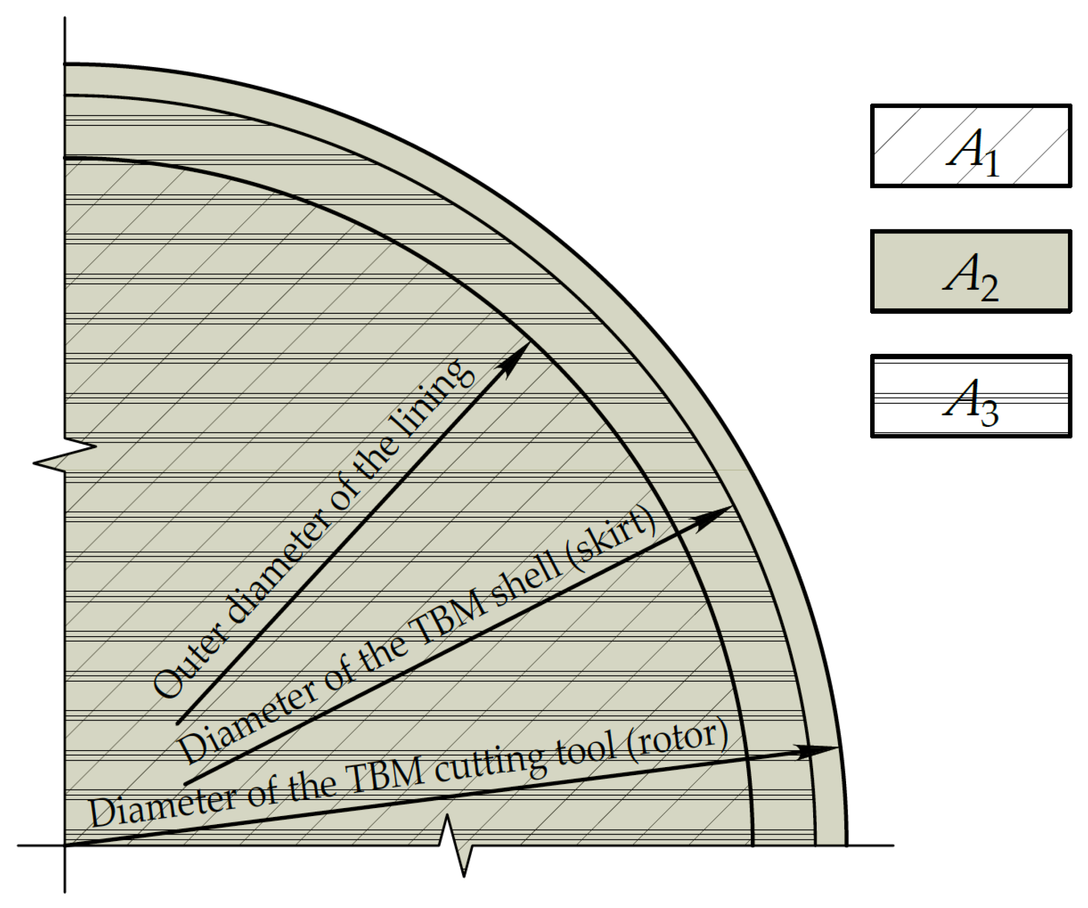
- Excavation of excess soil volume beyond the capacity of one ring, as indicated in the research by Mazein S.V. (2009) [6];
- Bentonite flows from the face to the tail of the TBM, pushing the injected cement mortar in the area where the last segment of the lining is installed;
- The injected cement mortar moves from the tail to the face, displacing the bentonite;
- Bentonite flows from the face to the tail of the TBM, while the injected cement mortar moves in the opposite direction.
2. Materials and Methods
- Lateral boundaries are fixed against lateral displacements but free in the vertical direction;
- The bottom boundary is fully fixed in all directions.
- First step: Creation of geometry and assignment of necessary loads, influences, stiffnesses, and boundary conditions;
- Second step: Specification of the initial SSS of the soil massive with generation of pore water pressure;
- Third step: Resetting the deformations of the previous step while retaining all stresses and continuing activation of existing structures under load conditions;
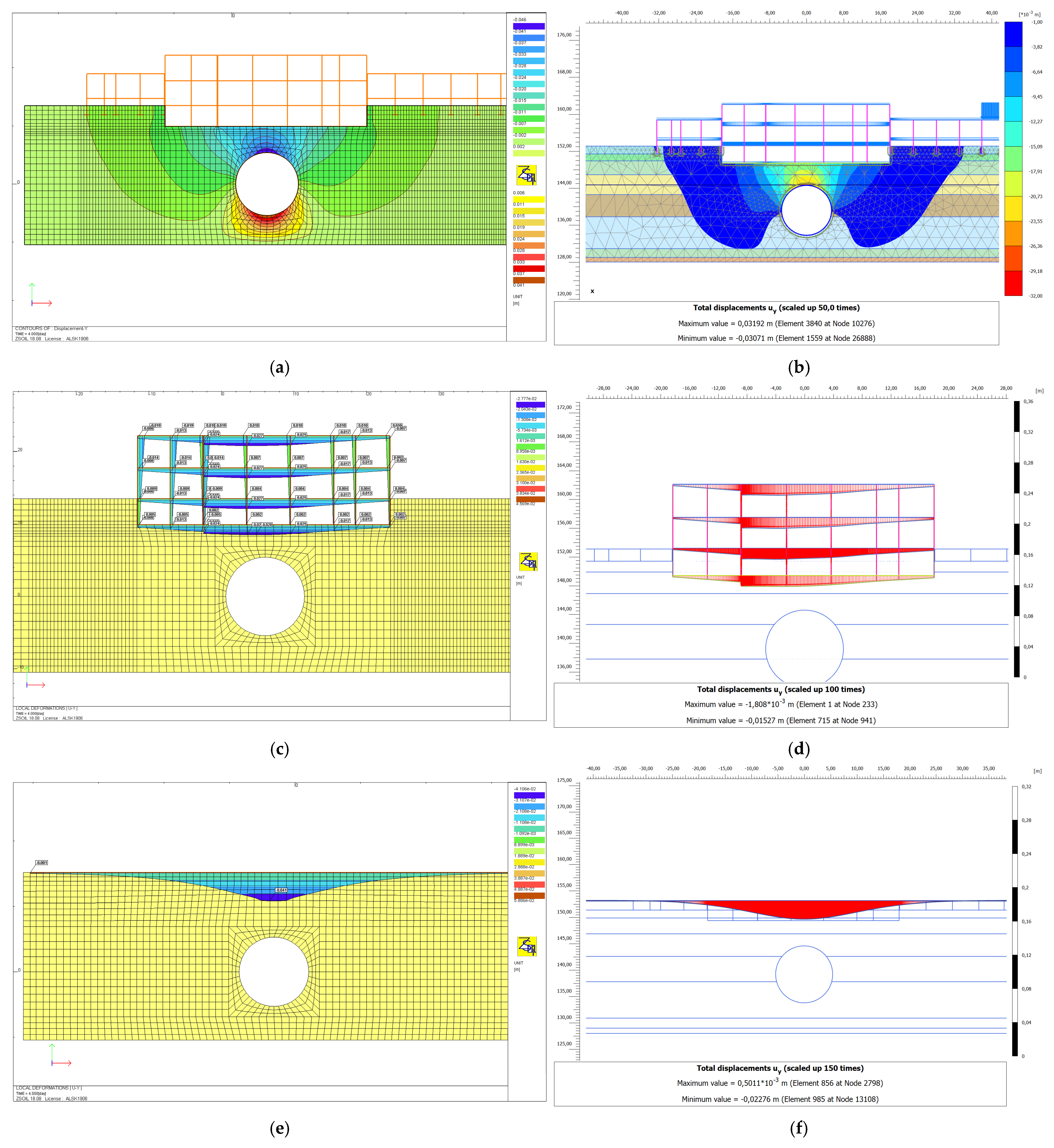
- Fourth step: Resetting the deformations of the previous step while retaining all stresses and continuing activation of the tunnel excavation with lining stiffness and at a given soil volume loss, which is modeled by structure shrinkage (axial or volumetric deformation).
3. Results
3.1. Validation Example 1
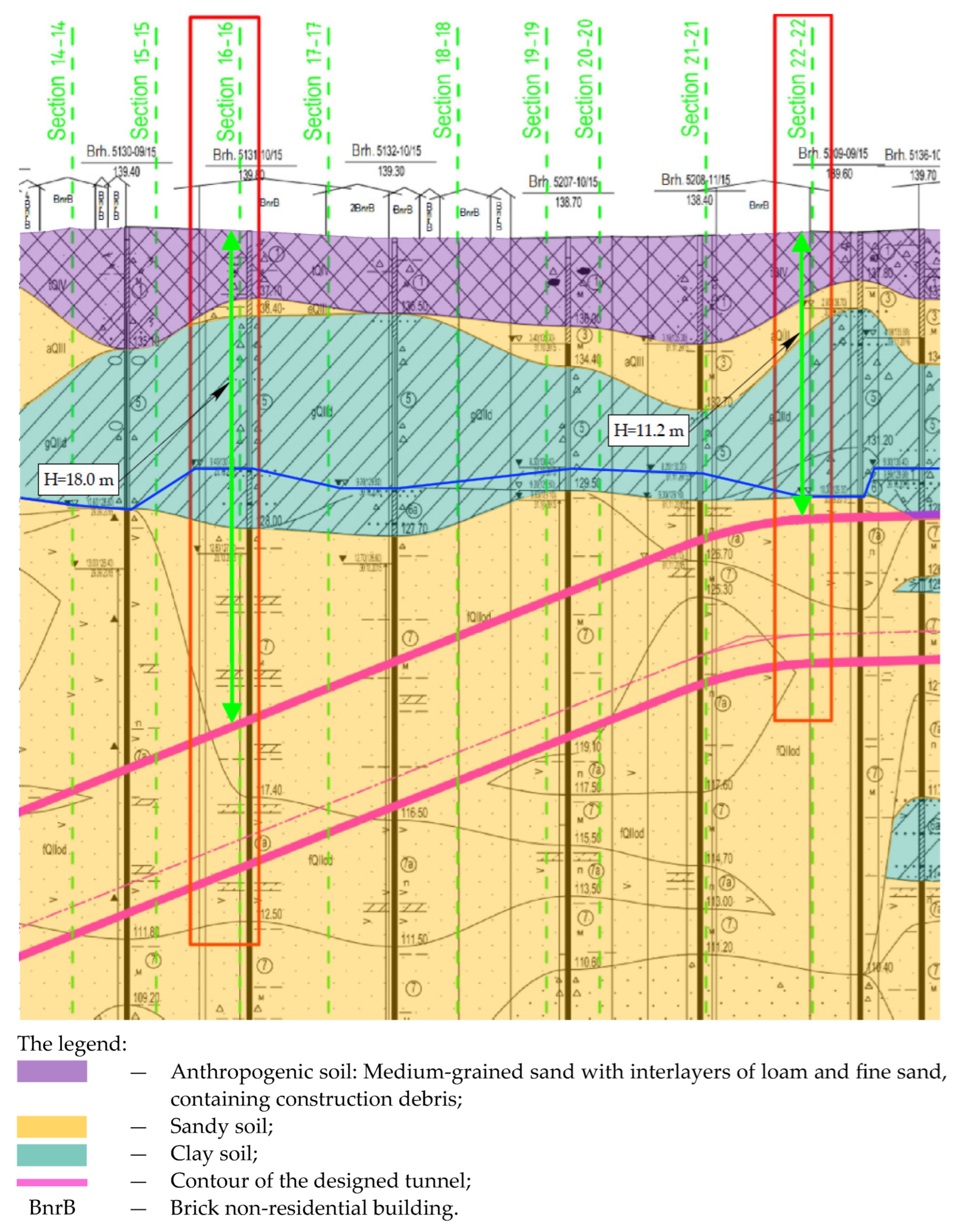
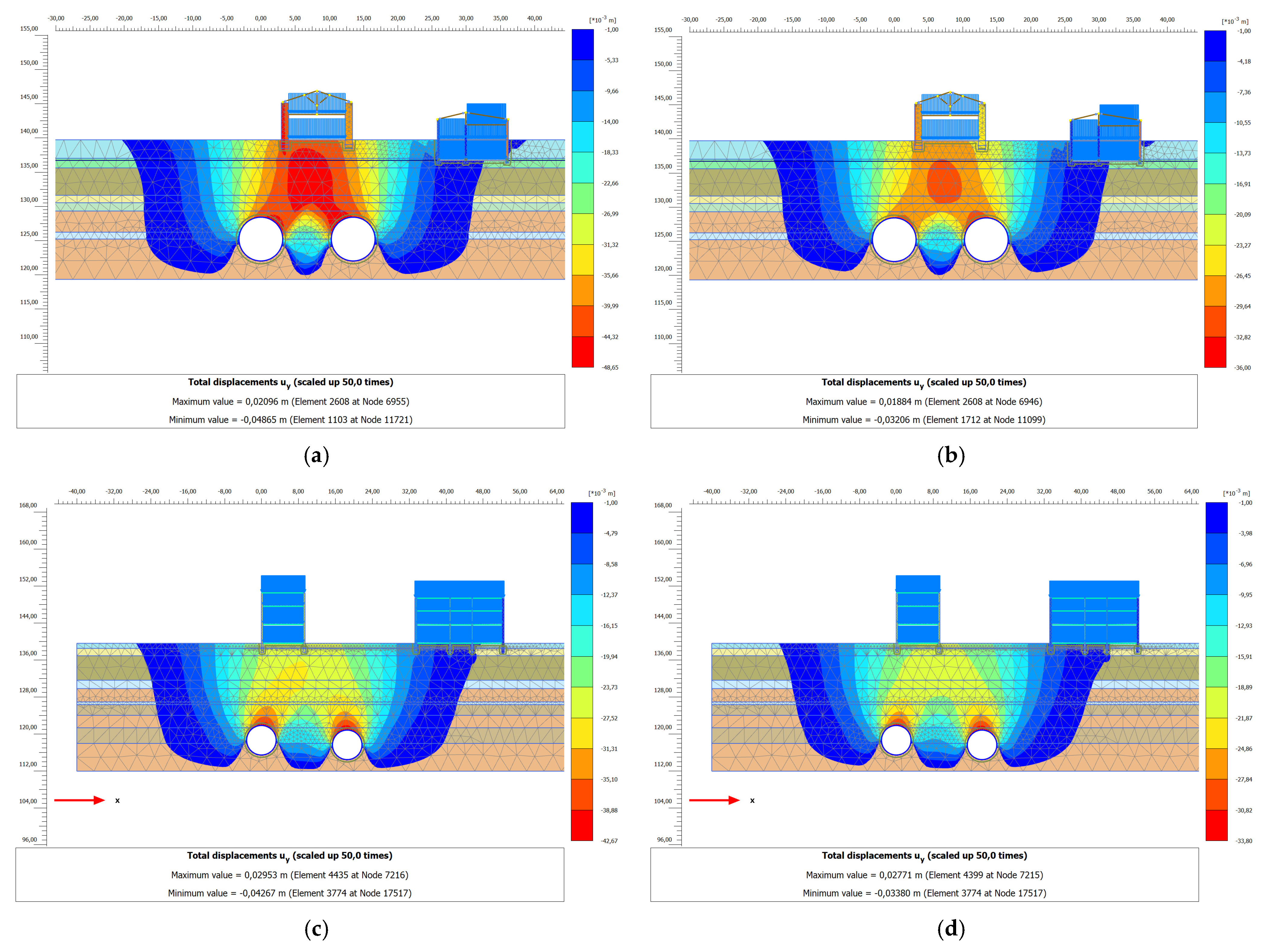
- Smirnovskaya str.; 10 bldg; seven prefabricated reinforced concrete frame with columns and beams on column foundations;
- Smirnovskaya str.; two bldg; 13 brick walls on rubble-stone strip foundations.
3.2. Validation Example 2
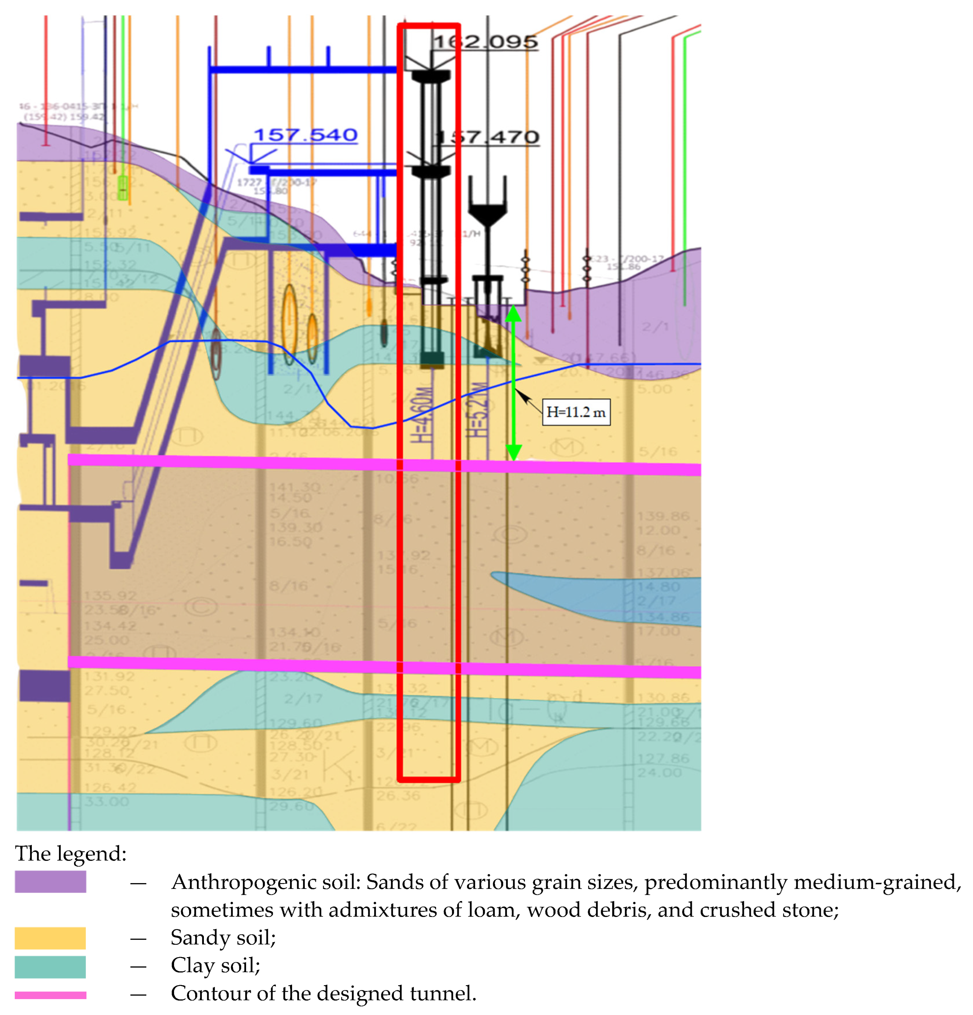
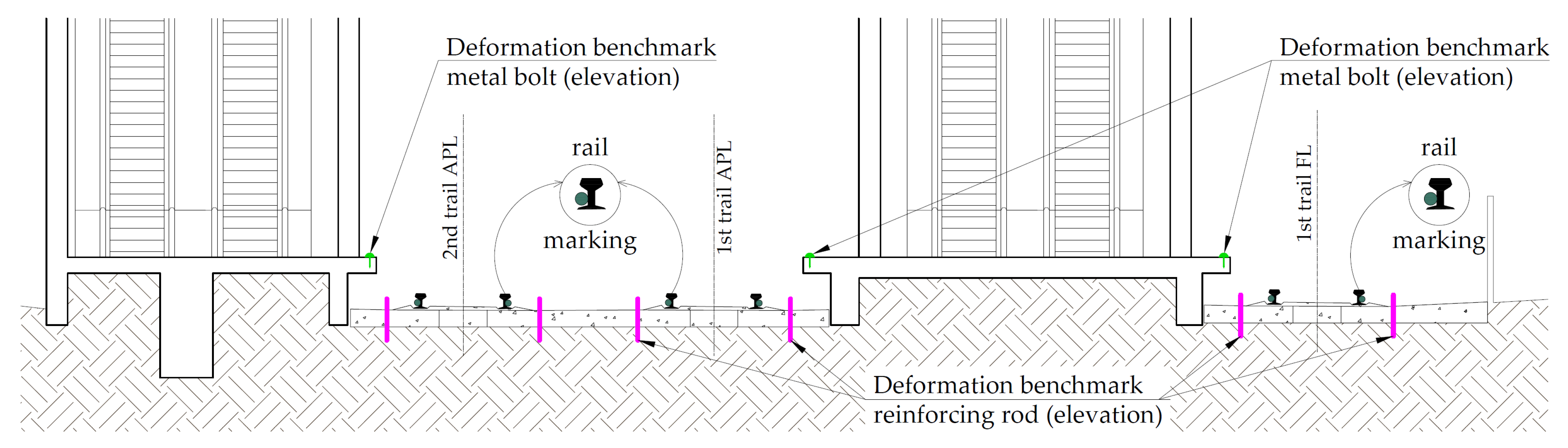
- Lobby—slab foundation;
- Platform—column foundation;
- Tracks—rail trestle lattice on a rigid concrete base.
3.3. Validation Example 3
3.4. Summary Validation Results
3.5. Validation of Modified Empirical Settlement Expression
- is an expression that accounts for relative additional stresses at the ground surface level or at the foundation depth, considering the that the applied load may be located at some distance from the tunnel axis.
3.6. Additional Validation for Modified Empirical Settlement Expression
4. Discussion
5. Conclusions
- The previously presented methods have been confirmed as effective, particularly when applied jointly in empirical calculations. This leads to a significant reduction in additional structural settlements under the soil conditions of the Moscow region compared with calculations based on previously established methods.
- The calculated volume loss in cohesionless (loose) soils, VL,LSR, generally shows good agreement with field monitoring data, indicating an acceptable engineering margin of safety.
- The newly modified Peck’s expression for calculating the maximum surface settlement Smax shows good agreement with field monitoring data, and its relative simplicity allows for a qualitative justification of design decisions for tunnel design in dense urban environments.
- Given that the application of the newly developed methodologies enables a reduction in final surface settlements for particularly critical tunneling sections and high-risk structures, this can significantly decrease the required scope of monitoring and the associated techniques. Since the frequency of monitoring during tunnel construction depends on the deformation rate, the methods applied may be limited to geodetic observations with a reduced number of deformation markers. It may also be possible to exclude the use of compensation and protective measures, as the expected structural settlements could remain well below critical thresholds. The proposed methodologies can assist in optimizing monitoring strategies and types, as well as compensation and protective actions; however, their use does not necessarily eliminate the need for such measures—the final decision always remains the responsibility of the designer.
- By analyzing a series of numerical simulation results, the authors observed that deformation patterns obtained from various software packages with different solvers, and those carried out by different engineers, exhibited similar patterns. This finding underscores that the accurate determination of volume loss (VL), a fundamental geomechanical parameter for predicting tunneling-induced settlements, is crucial.
- The authors intend to continue their research by validating the VL,LSR methodology and determining additional settlements using the modified Peck’s expression for calculating surface settlement Smax for a wider range of structures with available monitoring data. This effort aims to enhance the quality of tunnel design and construction, thereby reducing the likelihood of accidents.
Author Contributions
Funding
Data Availability Statement
Acknowledgments
Conflicts of Interest
References
- Sousa, R.L.; Einstein, H.H. Lessons from accidents during tunnel construction. Tunn. Undergr. Space Technol. 2021, 113, 103916. [Google Scholar] [CrossRef]
- Grandori, R.; Jaeger, M.; Antonini, F.; Vigl, L. Evinos-Mornos tunnel—Greece construction of a 30 km long hydraulic tunnel in less than three years under the most adverse geological conditions. In Proceedings of the RETC Proceedings, San Francisco, CA, USA, 18–21 June 1995; Society for Mining, Metallurgy, and Exploration: Englewood, CO, USA, 1995. [Google Scholar]
- Vlasov, S.N.; Makovsky, L.V.; Merkin, V.E.; Russian Tunnelling Association. Accidents in transportation and subway tunnels. In Construction to Operation; Elex-KM Publ. Ltd.: Moscow, Russia, 2001; p. 200. ISBN 5-93815-002-7. [Google Scholar]
- Tan, Y.; Lu, Y.; Wang, D. Catastrophic failure of Shanghai metro line 4 in July 2003: Occurrence, emergency response, and disaster relief. J. Perform. Constr. Facil. 2021, 35, 02021001. [Google Scholar] [CrossRef]
- Mazein, S.V. Instrumental Control, Forecast, and Adjustment of Working Parameters of Shield Driving. Min. Inf.-Anal. Bull. 2011, 6, 90–96. [Google Scholar]
- Mazein, S.V. Operational Control of Soil Porosity in Tunnel Shield Driving. Min. Inf.-Anal. Bull. 2009, 9, 106–115. [Google Scholar]
- Bezuijen, A. Bentonite and grout flow around a TBM. In Underground Space–The 4th Dimension of Metropolises, Three Volume Set+ CD-ROM, Proceedings of the World Tunnel Congress 2007 and 33rd ITA/AITES Annual General Assembly, Prague, Czech Republic, 5–10 May 2007; CRC Press: Prague, Czech Republic, 2007; p. 383. [Google Scholar]
- Nagel, F.; Meschke, G. Grout and Bentonite Flow Around a TBM: Computational Modeling and Simulation-Based Assessment of Influence on Surface Settlements. Tunn. Undergr. Space Technol. 2011, 26, 445–452. [Google Scholar] [CrossRef]
- Sagaseta, C. Analysis of undrained soil deformation due to ground loss. Géotechnique 1987, 37, 301–320. [Google Scholar] [CrossRef]
- Verruijt, A. A complex variable solution for a deforming circular tunnel in an elastic half-plane. Int. J. Numer. Anal. Methods Geomech. 1997, 21, 77–89. [Google Scholar] [CrossRef]
- Strack, O.E. Analytic Solutions of Elastic Tunneling Problems. Ph.D. Thesis, Delft University of Technology, Delft, The Netherlands, 2002. [Google Scholar]
- Lavasan, A.A.; Zhao, C.; Barciaga, T.; Schaufler, A.; Steeb, H.; Schanz, T. Numerical investigation of tunneling in saturated soil: The role of construction and operation periods. Acta Geotech. 2018, 13, 671–691. [Google Scholar] [CrossRef]
- Attewell, P.B.; Yeates, J.; Selby, A.R. Soil Movements Induced by Tunneling and Their Effects on Pipelines and Structures; Chapman and Hall: New York, NY, USA; Glasgow, UK; London, UK, 1986; p. 325. [Google Scholar]
- Ter-Martirosyan, A.Z.; Tikhoniuk, I.A. Overview of numerical methods for calculating the settlements of the soil surface during of tunneling. Constr. Geotech. 2025, 1, 47–81. [Google Scholar]
- Arioglu, E. Surface Movements Due to Tunnelling Activities in Urban Areas and Minimization of Building Damages; Istanbul Technical University, Mining Engineering Department: Istanbul, Turkey, 1992; p. 43. [Google Scholar]
- Lee, K.M.; Rowe, R.K.; Lo, K.Y. Subsidence owing to tunnelling. I. Estimating the gap parameter. Can. Geotech. J. 1992, 29, 929–940. [Google Scholar] [CrossRef]
- Loganathan, N.; Poulos, H.G. Analytical prediction for tunneling-induced ground movements in clays. J. Geotech. Geoenviron. Eng. 2011, 124, 846–856. [Google Scholar] [CrossRef]
- Macklin, S.R. The prediction of volume loss due to tunnelling in overconsolidated clay based on heading geometry and stability number. Ground Eng. 1999, 32, 30–33. [Google Scholar]
- Loganathan, N. An Innovative Method for Assessing Tunnelling-Induced Risks to Adjacent Structures; Parsons Brinckerhoff Inc.: New York, NY, USA, 2011; p. 118. [Google Scholar]
- Vu, M.N.; Broere, W.; Bosch, J. Volume loss in shallow tunnelling. Tunn. Undergr. Space Technol. 2016, 59, 77–90. [Google Scholar] [CrossRef]
- Ter-Martirosyan, A.Z.; Tikhoniuk, I.A. Methodology for determining volume loss during shield tunneling. Found. Soil Mech. 2025, 5, 25–30. [Google Scholar]
- Franza, A.; Marshall, A.M.; Haji, T.; Abdelatif, A.O.; Carbonari, S.; Morici, M. A simplified elastic analysis of tunnel-piled structure interaction. Tunn. Undergr. Space Technol. 2017, 61, 104–121. [Google Scholar] [CrossRef]
- Franza, A.; Losacco, N.; Ledesma, A.; Viggiani, G.M.B.; Jimenez, R. Protecting surface and buried structures from tunnelling using pile walls: A prediction model. Can. Geotech. J. 2021, 58, 1590–1602. [Google Scholar] [CrossRef]
- Song, G.; Xu, J.; Marshall, A.M. Numerical study on the effect of protective wall depth in reducing structure deformations caused by tunneling. Comput. Geotech. 2023, 158, 105374. [Google Scholar] [CrossRef]
- Franza, A. Comparison of floating and end-bearing pile wall barriers for tunnelling in layered soil. In Proceedings of the XVIII European Conference on Soil Mechanics and Geotechnical Engineering, Lisbon, Portugal, 26–30 August 2024. [Google Scholar]
- Xu, J.; Zheng, L.; Song, G.; Zhang, D.; Sheil, B.; Marshall, A.M. Effects of embedded walls on tunnelling-induced sandy ground displacements: A numerical investigation. Géotechnique 2024, 75, 472–485. [Google Scholar] [CrossRef]
- Masini, L.; Bergamo, F.; Rampello, S. Effect of soil improvement on ground movements induced by tunnelling. Tunn. Undergr. Space Technol. 2025, 155, 106163. [Google Scholar] [CrossRef]
- Xu, J.; Franza, A.; Marshall, A.M. Response of framed buildings on raft foundations to tunnelling. J. Geotech. Geoenviron. Eng. 2020, 146, 04020120. [Google Scholar] [CrossRef]
- Boldini, D.; Losacco, N.; Franza, A.; DeJong, M.J.; Xu, J.; Marshall, A.M. Tunnelling-induced deformation of bare frame structures on sand: Numerical study of building deformations. J. Geotech. Geoenviron. Eng. 2021, 147, 04021116. [Google Scholar] [CrossRef]
- Boldini, D.; Losacco, N.; Franza, A.; Miraei, S. Numerical modelling of framed structures with masonry infills affected by tunnelling-induced deformation and damage. In Geotechnical Aspects of Underground Construction in Soft Ground; Elshafie, M.Z., Viggiani, G.M., Mair, R.J., Eds.; CRC Press: Cambridge, UK, 2021; pp. 510–516. [Google Scholar] [CrossRef]
- Xu, J.; Franza, A.; Marshall, A.M.; Losacco, N. Role of footing embedment on tunnel–foundation interaction. J. Geotech. Geoenviron. Eng. 2021, 147, 06021009. [Google Scholar] [CrossRef]
- Xu, J.; Franza, A.; Marshall, A.M.; Losacco, N.; Boldini, D. Tunnel–framed building interaction: Comparison between raft and separate footing foundations. Géotechnique 2021, 71, 631–644. [Google Scholar] [CrossRef]
- Xu, J.; Gui, J.; Sheil, B. A numerical investigation of the role of basements on tunnel-frame interaction in sandy soil. Comput. Geotech. 2024, 169, 106197. [Google Scholar] [CrossRef]
- Yu, Y.; Franza, A.; Neves, L.; Marshall, A.M. Effect of infill nonlinearity on frame response to tunnelling. In Proceedings of the IS-Macau 2024: 11th International Symposium of Geotechnical Aspects of Underground Construction in Soft Ground, Macao SAR, China, 14–17 June 2024. [Google Scholar]
- Yu, Y.; Franza, A.; Ghiassi, B.; Neves, L.C.; Marshall, A.M. Tunneling-induced wall damage: An appraisal of elastoplasticconstitutive models for masonry. Tunn. Undergr. Space Technol. 2025, 156, 106240. [Google Scholar] [CrossRef]
- Ter-Martirosyan, A.Z.; Isaev, I.O.; Almakaeva, A.S. Determination of actual volume loss coefficient (Section “Stakhanovskaya St.”–“Nizhegorodskaya St.”). Vestn. MGSU 2020, 15, 1644–1653. [Google Scholar] [CrossRef]
- Peck, R.B. Deep excavation and tunneling in soft ground. State of the art report. In Proceedings of the 7th International Conference on Soil Mechanics and Foundation Engineering, Mexico City, Mexico, 22–30 August 1969; pp. 147–150. [Google Scholar]
- Rong, X.; Liu, Z.; Zhang, Y.; Wu, J. Analysis of ground volume loss for EPB shield tunneling in thick silty clay layer. Alex. Eng. J. 2024, 96, 295–302. [Google Scholar] [CrossRef]
- Zhu, B.; Zhang, P.; Lei, M.; Wang, L.; Gong, L.; Gong, C.; Chen, F. Improved analytical solution for ground movements induced by circular tunnel excavation based on ground loss correction. Tunn. Undergr. Space Technol. 2023, 131, 104811. [Google Scholar] [CrossRef]
- Tikhoniuk, I.A.; Filatov, Y.V. Determination of the complex volume loss of soils during underground shield tunneling. Geotechnics 2022, 14, 30–48. [Google Scholar] [CrossRef]
- SP 249.1325800.2016; Underground Utilities. Design and Construction by Closed and Open Methods. Ministry of Construction, Housing, and Utilities of the Russian Federation: Moscow, Russia, 2016.
- Protodyakonov, M.M. Rock pressure on mine support. Min. J. 1909, 7. [Google Scholar]
- Bieniawski, Z.T. Engineering Rock Mass Classifications: A Complete Manual; John Wiley & Sons: New York, NY, USA, 1989; 272p. [Google Scholar]
- Barton, N.; Løset, F.; Lien, R.; Lunde, J. Application of the Q-System in design decisions concerning dimensions and appropriate support for underground installations. In Proceedings of the International Conference on Sub-Surface Space, Rock Store, Stockholm, Sweden, 23–27 June 1980; Volume 2, pp. 553–561. [Google Scholar]
- Mohr, O. Ueber die Darstellung des Span-nungszustandes und des Deformationszustandes eines K/r-perelementes und über die Anwendung derselben in der Fes-tigkeitslehre. Civilengenieur 1882, 28, 113–156. [Google Scholar]
- Coulomb, C.A. Essai sur une application des regles des maximis et minimis a quelquels problemesde statique relatifs, a la architecture. Mémoires l’Académie R. Sci. Div. Savants 1776, 7, 343–387. [Google Scholar]
- Sharafutdinov, R.F.; Isaev, O.N.; Zakatov, D.S. A study of the ground volume loss modeling technique influence the soil displacement in course of shield tunneling. In Smart Geotechnics for Smart Societies; Zhussupbekov, A., Sarsembayeva, A., Kaliakin, V.N., Eds.; CRC Press: London, UK, 2023; pp. 1042–1051. [Google Scholar] [CrossRef]
- Ter-Martirosyan, A.Z.; Babushkin, N.F.; Isaev, I.O.; Shishkina, V.V. Determination of actual volume loss coefficient through monitoring data analysis. Geotechnics 2020, 7, 34–42. [Google Scholar]
- Ter-Martirosyan, A.Z.; Kivlyuk, V.P.; Isaev, I.O.; Shishkina, V.V. Determination of actual volume loss coefficient (section “Kosino”–“Yugo-Vostochnaya”). Constr. Geotech. 2021, 12, 5–14. [Google Scholar] [CrossRef]
- Ter-Martirosyan, A.Z.; Cherkesov, R.H.; Isaev, I.O.; Rud, V.V. Actual volume loss coefficient for tunnels in dispersive and rock soils. Hous. Constr. 2023, 9, 61–73. [Google Scholar] [CrossRef]
- Muir Wood, A.M. The Circular Tunnel in Elastic Ground. Geotechnique 1975, 25, 115–127. [Google Scholar] [CrossRef]
- Skempton, A.W.; Henkel, D.J. The post-glacial clays of the thames estuary at tillbury and shellhaven. In Proceedings of the Third International Conference on Soil Mechanics and Foundation Engineering, Zurich, Switzerland, 16–27 August 1953; Volume 1, pp. 302–308. [Google Scholar]
- O’Reilly, M.P.; New, B.M. Settlements above tunnels in the United Kingdom—Their magnitude and prediction. In Tunnelling 82, Proceedings of the 3rd International Symposium, Brighton, UK, 7–11 June 1982; IMM: London, UK, 1982; pp. 173–181. [Google Scholar]
- Lee, C.J.; Wu, B.R.; Chiou, S.Y. Soil movements around a tunnel in soft soils. Proc. Natl. Sci. Counc. Part A Phys. Sci. Eng. 1999, 23, 235–247. [Google Scholar]
- Tupikov, M.M. Features of Soil Mass and Structure Deformation During Construction of Shallow Utility Tunnels in Urban Conditions. Ph.D. Thesis, RUT MIIT, Moscow, Russia, 2010. [Google Scholar]
- Chakeri, H.; Ünver, B. A new equation for estimating the maximum surface settlement above tunnels excavated in soft ground. Environ. Earth Sci. 2014, 71, 3195–3210. [Google Scholar] [CrossRef]
- Wang, F.; Miao, L.; Yang, X.; Du, Y.J.; Liang, F.Y. The volume of settlement trough change with depth caused by tunneling in sands. KSCE J. Civ. Eng. 2016, 20, 2719–2724. [Google Scholar] [CrossRef]
- ANO ANTC RAASN. Recommendations for Evaluation of the Impact of Collector Tunneling on the Settlement of Surrounding Buildings and Underground Structures; ANO ANTC RAASN: Moscow, Russia, 2007. [Google Scholar]
- Mair, R.J. General report on settlement effects of bored tunnels. In Geotechnical Aspects of Underground Construction in Soft Ground, Proceedings of the International Symposium City University, London, UK, 15–17 April 1996; Balkema: Rotterdam, The Netherlands, 1996; pp. 43–53. [Google Scholar]
- Ou, C.-Y.; Hwang, R.N.; Lai, W.J. Surface settlement during shield tunnelling at CH218 in Taipei. Can. Geotech. J. 1998, 35, 159–168. [Google Scholar] [CrossRef]
- Tikhoniuk, I.A. Review of analytical and empirical methods for calculating surface settlement during shield tunneling. Constr. Geotech. 2024, 15, 78–101. [Google Scholar]
- GOST 24846-2019; Soils. Methods for Measuring Deformations of Building and Structure Foundations. Interstate Council for Standardization, Metrology and Certification (ISC): Moscow, Russia, 2019.


 VL by Loganathan N. (2011) [19];
  VL,LSR [21].



| Ratio | Parameter of Soil | Intervals of Values of the Characteristics of Cohesionless (Loose) Soils | ||||||
|---|---|---|---|---|---|---|---|---|
| RC | C, kPa | ≥60 | 50 | 40 | 30 | 20 | 10 | 0 |
| 0.32 | 0.25 | 0.20 | 0.15 | 0.10 | 0.05 | 0 | ||
| Rφ | φ, (°) | ≥35 | 30 | 25 | 20 | 15 | 10 | 0 |
| 0.15 | 0.10 | 0.08 | 0.05 | 0.03 | 0.02 | 0 | ||
| Re | υ | ≤0.25 | 0.27 | 0.3 | 0.35 | 0.4 | ≥0.45 | |
| 0.15 | 0.10 | 0.07 | 0.04 | 0.02 | 0 | |||
| RE0 | E0, MPa | ≥50.0 | 35.0 | 25.0 | 20.0 | 15.0 | ≤10.0 | |
| 0.08 | 0.06 | 0.04 | 0.02 | 0.01 | 0 | |||
| Re | e | ≤0.4 | 0.5 | 0.55 | 0.6 | 0.7 | 0.75 | ≥0.8 |
| 0.15 | 0.12 | 0.09 | 0.07 | 0.04 | 0.03 | 0 | ||
| RIL | IL | ≤0 | 0.25 | 0.5 | 0.75 | ≥1 | ||
| 0.15 | 0.10 | 0.05 | 0.01 | 0 | ||||
| Soil | Cohesion c, kPa | Internal Friction Angle φ, Deg (°) | Poisson’s Ratio ν | Young’s Modulus E0, MPa | Porosity Coefficient e | Number of Fluidity IL |
|---|---|---|---|---|---|---|
| EGE-7 Sand | 0 | 31 | 0.3 | 25.0 | 0.67 | - |
| EGE-7a Sand | 0 | 27 | 0.3 | 19.0 | 0.72 | - |
| Soil | Cohesion c, kPa | Internal Friction Angle φ, Deg (°) | Poisson’s Ratio ν | Young’s Modulus E0, MPa | Porosity Coefficient e | Number of Fluidity IL |
|---|---|---|---|---|---|---|
| EGE-2/16 Sand | 4 | 34 | 0.3 | 29.0 | 0.55 | - |
| EGE-5/16 Sand | 3 | 35 | 0.3 | 37.0 | 0.54 | - |
| EGE-8/16 Sand | 2 | 35 | 0.3 | 45.0 | 0.52 | - |
| Soil | Cohesion c, kPa | Internal Friction Angle φ, Deg (°) | Poisson’s Ratio ν | Young’s Modulus E0, MPa | Porosity Coefficient e | Number of Fluidity IL |
|---|---|---|---|---|---|---|
| EGE-112 Loam | 36 | 22 | 0.352 | 29.0 | 0.47 | 0.1 |
| EGE-134 Sand | 2 | 35 | 0.3 | 45.0 | 0.52 | - |
| Ex. No. | Address of the Structure/Name of the Object | Distance to Foundations or Structure, m | Tunnel Diameter, m, and Type of TBM | Ultimate Additional Settlement Smax, mm | Design Volume Loss VL, % | Validation Settlement Smax, mm | Methodology VL,LSR, % | Validation Settlement Smax, mm | Monitoring Data |
|---|---|---|---|---|---|---|---|---|---|
| 1 | Tunneling under buildings at str. Smirnovskaya | ||||||||
| 1.1 | Smirnovskaya str., 10 bldg. 7 | ~15.8 | ∅6.2 EBP | 30 | 1.75 | 28.8 | 1.19 2 1.51 | 21.0 | 9.1 4 |
| 1.2 | Smirnovskaya str., two bldg. 13 | ~10.0 | 30 | 45.2 13.3 1 | 1.51 | 29.3 | 10.8 4 | ||
| 2 | Tunneling under buildings at the Kuntsevskaya station | ||||||||
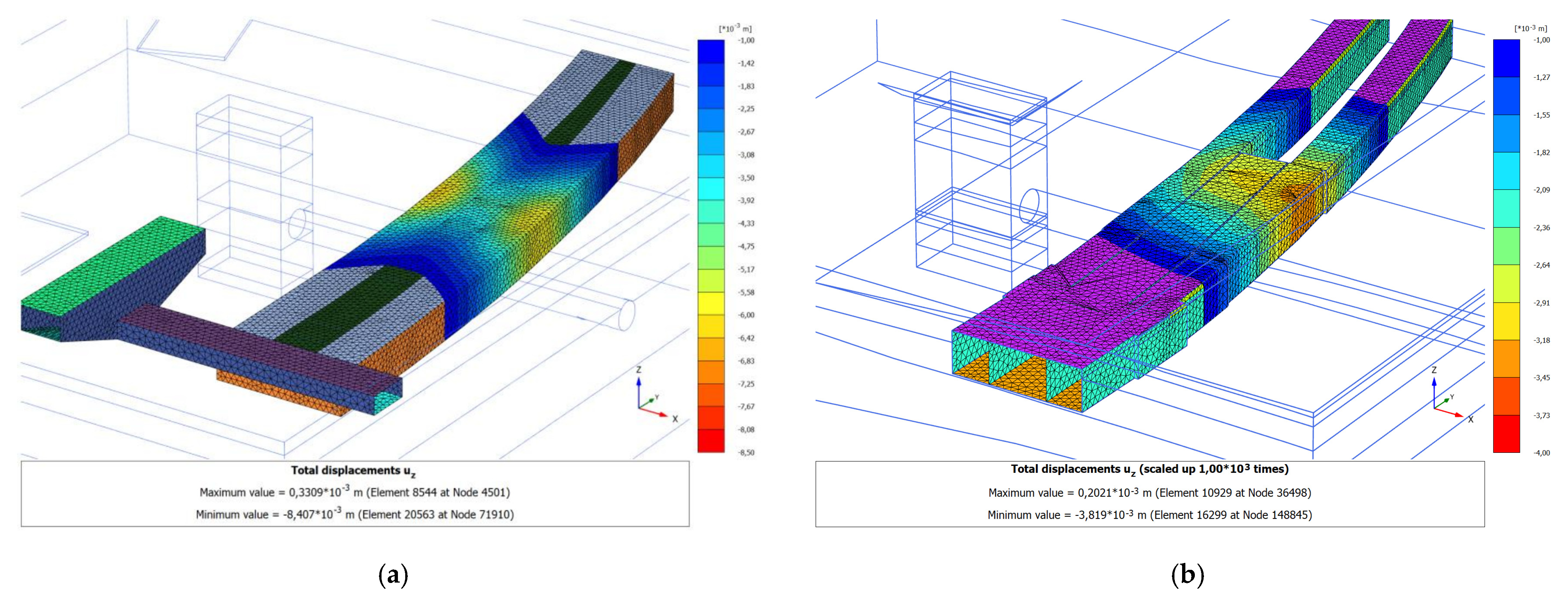
| 2.1 | Western lobby Kuntsevskaya St. (APL/FL) | ~5.0 | ∅10.5 EBP | 31 | 1.3 | 28.0 | 0.75 | 15.3 | 9.3 / 12.7 |
| 2.2 | Platform Kuntsevskaya St. | ~6.8 | 31 | 8.0 | 4.1 | 3.2 | |||
| 2.3 | Tracks 1 and 2 APL and track 1 FL Kuntsevskaya St. | ~8.5 | 11 | 41.0 | 22.8 | 16.4 | |||
| 3 | Tunneling under buildings at the Akademicheskaya station | ||||||||
| 3.1 | Akademicheskaya St. | ~4.0 | ∅4.1 EBP | 30 | 1.5 | 8.7 | 1.16% 2.21% 3 | 3.8 | 3.6 |
| No. | Name or Address of the Facility | Tunnel Diameter, m | VL Calculation Method, % | |
|---|---|---|---|---|
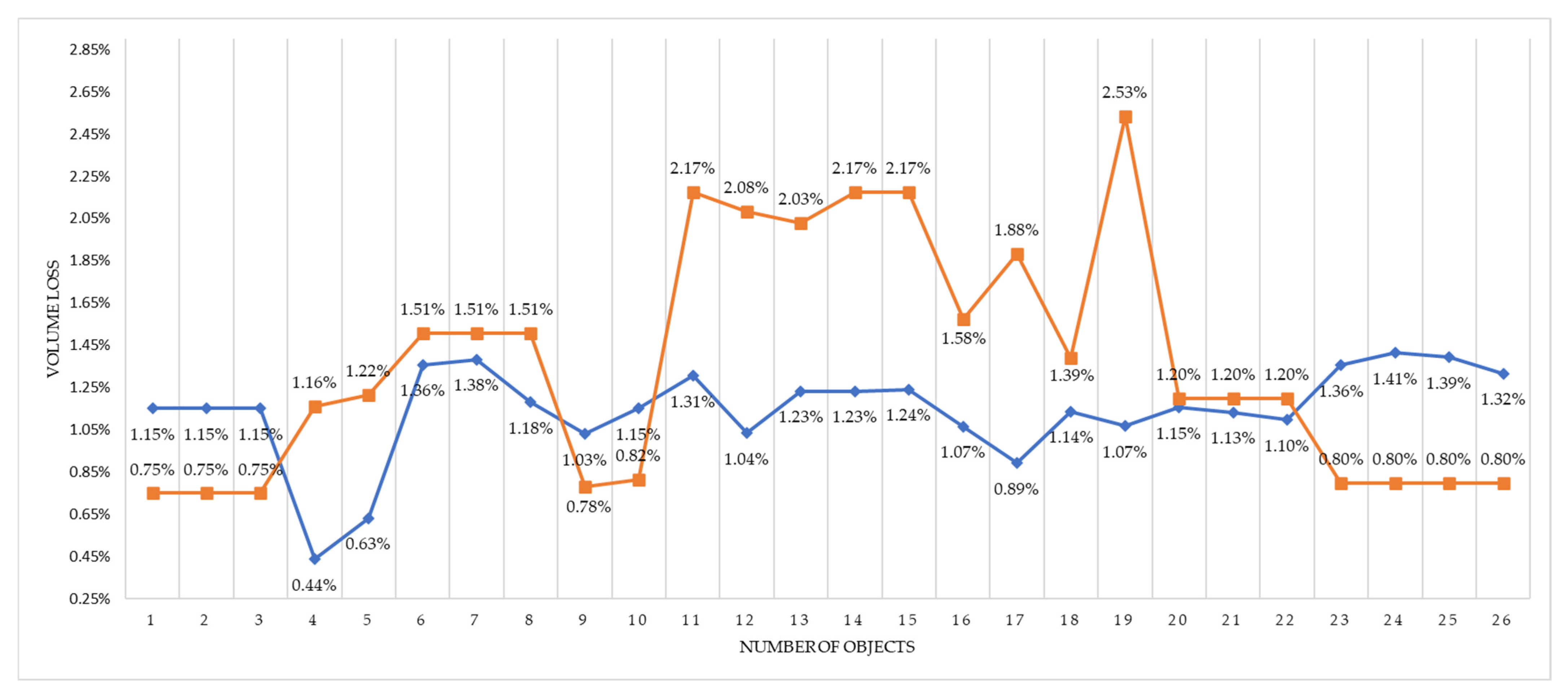
| Loganathan N. (2011) [19] | VL,LSR [21] | |||
| 1 | Western lobby Kuntsevskaya St. (APL/FL) | ∅10.5 | 1.15 | 0.75 |
| 2 | Platform Kuntsevskaya St. | |||
| 3 | Tracks 1 and 2 APL and track 1 FL Kuntsevskaya St. | |||
| 4 | Akademicheskaya St. | ∅4.3 | 0.44 | 1.16 |
| 5 | ZML 1 tunnels from PC 115 + 53.140 to PC 117 + 57.600 | ∅6.0 | 0.63 | 1.22 |
| 6 | Smirnovskaya str., 10 bldg. 24 | 1.36 | 1.51 | |
| 7 | Smirnovskaya str., 10 bldg. 7 | 1.38 | ||
| 8 | Smirnovskaya str., two bldg. 13 | 1.18 | ||
| 9 | 1-ya Novokuzminskaya str., 1 | ∅10.5 | 1.03 | 0.78 |
| 10 | 1-ya Novokuzminskaya str., 3 | 1.15 | 0.82 | |
| 11 | Andropova ave., 39 bldg. 46 | 1.31 | 2.17 | |
| 12 | Andropova ave., 39 bldg. 63 | 1.04 | 2.08 | |
| 13 | Andropova ave., 39 bldg. 82 | 1.23 | 2.03 | |
| 14 | Shtatnaya str., 19 | 2.17 | ||
| 15 | Shtatnaya str., 19A | |||
| 16 | Bolshaya str., 128 | 1.07 | 1.58 | |
| 17 | 2nd Silikatny proezd, 7 bldg. 2, str. 4 | ∅6.0 | 0.89 | 1.88 |
| 18 | 2nd Silikatny prospekt, 9 bldg. 11 | 1.14 | 1.39 | |
| 19 | Shenogina str., two bldg. 33 | 1.07 | 2.53 | |
| 20 | Ryazansky prospekt, 22 | ∅10.5 | 1.15 | 1.20 |
| 21 | Ryazansky prospekt, two bldg. 27 [36] | 1.13 | ||
| 22 | Ryazansky prospekt, 4A bldg. 2 [36] | 1.13 | ||
| 23 | MCAR 2 8 km, vl. 3 bldg. 2. BC “Drive” [49] | 1.36 | 0.8 | |
| 24 | Ferganskaya str., 25 bldg. 2 [49] | 1.41 | ||
| 25 | Samarkand boulevard, 134 bldg. 5 [49] | 1.39 | ||
| 26 | Ferganskaya str., 23 [49] | 1.32 | ||
| No. | Name or Address of the Facility | Depth from the Surface to the Center of the Tunnel | Depth from the Surface to the Bottom of the Foundation | Diameter of the Tunnel Along the Outer Edge of the Lining | Distance from the Edge of the Foundation to the Tunnel Axis | Pressure Under the Base of the Building Foundation | Cohesion | Internal Friction Angle | Poisson’s Ratio | Young’s Modulus | Porosity Coefficient | Number of Fluidity |
|---|---|---|---|---|---|---|---|---|---|---|---|---|
| z0 [m] | z [m] | D [m] | L [m] | P [kPa] | c [kPa] | ˚ [deg] | υ [–] | E0 [MPa] | e [–] | IL [–] | ||
| 1 | Table 6 and Table 8. Position 1 | 13.9 | 3.7 | 10.5 | 0 | 66 | 4 | 34 | 0.3 | 29 | 0.55 | 0 |
| 2 | Table 6 and Table 8. Position 2 | 13.9 | 1.7 | 10.5 | 18 | 130 | 4 | 34 | 0.3 | 29 | 0.55 | 0 |
| 3 | Table 6 and Table 8. Position 3 | 13.9 | 0 | 10.5 | 0 | 101.7 | 4 | 34 | 0.3 | 29 | 0.55 | 0 |
| 4 | Table 6 and Table 8. Position 4 | 14.1 | 7.9 | 4.3 | 0 | 130.8 | 36 | 22 | 0.352 | 29 | 0.47 | 0.10 |
| 5 | Table 6 and Table 8. Position 5 | 16.8 | 8.3 | 6.0 | 0 | 135.3 | 50 | 25 | 0.35 | 28.7 | 0.47 | 0.17 |
| 6 | Table 6 and Table 8. Position 6 | 19.9 | 3.5 | 6.0 | 0 | 390 | 0 | 27 | 0.3 | 19 | 0.72 | 0 |
| 7 | Table 6 and Table 8. Position 7 | 21.1 | 2 | 6.0 | 0 | 250 | 0 | 27 | 0.3 | 19 | 0.72 | 0 |
| 8 | Table 6 and Table 8. Position 8 | 14.5 | 1.3 | 6.0 | 0 | 155 | 0 | 27 | 0.3 | 19 | 0.72 | 0 |
| 9 | Table 6 and Table 8. Position 9 | 19.2 | 1.6 | 10.5 | 0 | 60 | 3 | 38 | 0.29 | 32 | 0.65 | 0 |
| 10 | Table 6 and Table 8. Position 10 | 24.2 | 1.6 | 10.5 | 3.4 | 72 | 3 | 35 | 0.31 | 29 | 0.63 | 0 |
| 11 | Table 6 and Table 8. Position 11 | 27.2 | 1.5 | 10.5 | 1.5 | 27 | 5 | 31 | 0.29 | 26.2 | 0.71 | 0 |
| 12 | Table 6 and Table 8. Position 12 | 21.0 | 2.3 | 10.5 | 7 | 36 | 1 | 33 | 0.31 | 31.8 | 0.65 | 0 |
| 13 | Table 6 and Table 8. Position 13 | 22.6 | 1.8 | 10.5 | 0.5 | 55 | 2 | 34 | 0.31 | 25.6 | 0.63 | 0 |
| 14 | Table 6 and Table 8. Position 14 | 23.2 | 2.4 | 10.5 | 0 | 36 | 5 | 31 | 0.29 | 26.2 | 0.71 | 0 |
| 15 | Table 6 and Table 8. Position 15 | 23.2 | 1.8 | 10.5 | 30.9 | 27 | 5 | 31 | 0.29 | 26.2 | 0.71 | 0 |
| 16 | Table 6 and Table 8. Position 16 | 18.5 | 1.7 | 10.5 | 22.2 | 27 | 30 | 20 | 0.35 | 20.5 | 0.63 | 0.33 |
| 17 | Table 6 and Table 8. Position 17 | 23.4 | 1.9 | 6.0 | 6.6 | 281.3 | 30 | 23 | 0.36 | 21 | 0.60 | 0.35 |
| 18 | Table 6 and Table 8. Position 18 | 25.9 | 1.9 | 6.0 | 23.4 | 281.3 | 54 | 20 | 0.32 | 22 | 0.73 | 0.09 |
| 19 | Table 6 and Table 8. Position 19 | 24.9 | 1.8 | 6.0 | 17.4 | 187.5 | 2 | 32 | 0.31 | 28 | 0.58 | 0 |
| 20 | Table 6 and Table 8. Position 20 | 30.2 | 2.0 | 10.5 | 9.6 | 24 | 4 | 32 | 0.31 | 26 | 0.62 | 0 |
| 21 | Table 6 and Table 8. Position 21 | 27.3 | 1.9 | 10.5 | 0 | 24 | 4 | 32 | 0.31 | 26 | 0.62 | 0 |
| 22 | Table 6 and Table 8. Position 22 | 26.7 | 2.2 | 10.5 | 0 | 236.3 | 4 | 32 | 0.31 | 26 | 0.62 | 0 |
| 23 | Table 6 and Table 8. Position 23 | 25.3 | 3.4 | 10.5 | 0 | 75 | 4 | 35 | 0.29 | 23.8 | 0.63 | 0 |
| 24 | Table 6 and Table 8. Position 24 | 27.3 | 2.35 | 10.5 | 34.8 | 225 | 4 | 35 | 0.29 | 23.8 | 0.63 | 0 |
| 25 | Table 6 and Table 8. Position 25 | 26.4 | 3.3 | 10.5 | 25.4 | 300 | 4 | 35 | 0.29 | 23.8 | 0.63 | 0 |
| 26 | Table 6 and Table 8. Position 26 | 22.2 | 2.5 | 10.5 | 0 | 45 | 4 | 35 | 0.29 | 23.8 | 0.63 | 0 |
| No. | Name or Address of the Facility | Peck R.B. (1969) [37] | Peck R.B. (1969) [37] with VL по [19] | O’Reilly M.P. and New B.N. (1982) [53] | Lee C.J. et al. (1999) [54] | Tupikov M.M. (2010) [55] | Chakeri H. and Ünver B. (2014) [56] | Wang F. et al. (2016) [57] | Smax by VL,LSR (2025) [21] | Monitoring Data |
|---|---|---|---|---|---|---|---|---|---|---|
| 1 | Western lobby Kuntsevskaya St. (APL/FL) | 26.0 | 39.9 | 36.7 | 26.6 | 21.3 | 19.4 | 37.3 | 14.8 | 9.3/ 12.7 |
| 2 | Platform Kuntsevskaya St. | 5.1 | 7.8 | 36.7 1 | 26.6 1 | 7.3 | 22.9 1 | 5.9 | 3.4 | 3.2 |
| 3 | Tracks 1 and 2 APL and track 1 FL Kuntsevskaya St. | 26.0 | 39.9 | 36.7 | 26.6 | 21.3 | 21.4 | 24.5 | 13.0 | 16.4 |
| 4 | Akademicheskaya St. | 12.8 | 4.8 | 17.5 | 10.0 | 13.6 | 10.7 | 90.5 | 9.3 | 3.6 |
| 5 | ZML tunnels from PC 115 + 53.140 to PC 117 + 57.600 | 17.0 | 8.8 | 29.9 | 16.0 | 12.8 | 12.9 | 71.6 | 12.4 | 5.6 |
| 6 | Smirnovskaya str., 10 bldg. 24 | 16.4 | 14.8 | 17.6 | 18.0 | 18.0 | 28.7 | 30.2 | 12.2 | 10.8 2 |
| 7 | Smirnovskaya str., 10 bldg. 7 | 16.4 | 15.1 | 16.8 | 17.4 | 21.0 | 23.2 | 37.7 | 9.5 | 9.1 2 |
| 8 | Smirnovskaya str., two bldg. 13 | 20.2 | 15.9 | 23.5 | 21.7 | 12.5 | 24.0 | 55.3 | 12.4 | 1.8 2 |
| 9 | 1-ya Novokuzminskaya str., 1 | 23.3 | 30.9 | 28.8 | 22.9 | 14.5 | 14.4 | 21.0 | 10.9 | 14.7 |
| 10 | 1-ya Novokuzminskaya str., 3 | 19.0 | 26.8 | 24.5 1 | 21.0 1 | 11.7 | 15.7 1 | 16.7 | 10.0 | 12.3 |
| 11 | Andropova ave., 39 bldg. 46 | 47.5 | 28.5 | 58.8 1 | 52.3 1 | 31.9 | 17.8 1 | 39.5 | 24.4 | 17.2 |
| 12 | Andropova ave., 39 bldg. 63 | 41.4 | 20.6 | 71.2 1 | 58.2 1 | 26.3 | 15.0 1 | 48.2 | 25.2 | 9.4 |
| 13 | Andropova ave., 39 bldg. 82 | 44.5 | 27.0 | 65.0 1 | 54.4 1 | 26.4 | 17.8 1 | 46.3 | 26.6 | 6.4 |
| 14 | Shtatnaya str., 19 | 47.7 | 27.1 | 68.0 1 | 57.4 1 | 28.4 | 18.7 1 | 50.2 | 28.3 | 12.5 |
| 15 | Shtatnaya str., 19A | 7.0 | 4.0 | 66.7 1 | 56.7 1 | 14.5 | 18.3 1 | 10.0 | 3.3 | 3.3 |
| 16 | Bolshaya str., 128 | 1.3 | 0.9 | 107.4 1 | 47.4 1 | 6.9 | 25.4 1 | 11.8 | 7.8 | 5.8 |
| 17 | 2nd Silikatny proezd, 7 bldg. 2, str. 4 | 18.8 | 8.9 | 33.0 1 | 20.4 1 | 35.2 | 19.5 1 | 38.7 | 9.7 | 7.4 |
| 18 | 2nd Silikatny prospekt, 9 bldg. 11 | 1.6 | 1.3 | 20.2 1 | 13.5 1 | 2.4 | 19.1 1 | 13.4 | 2.9 | 1.2 |
| 19 | Shenogina str., two bldg. 33 | 8.8 | 3.7 | 20.3 1 | 23.7 1 | 17.5 | 11.1 1 | 31.1 | 5.7 | 1.7 |
| 20 | Ryazansky prospekt, 22 | 21.4 | 20.6 | 31.0 1 | 28.0 1 | 17.1 | 16.3 1 | 19.3 | 11.2 | 13.4 |
| 21 | Ryazansky prospekt, two bldg. 27 [22] | 26.7 | 25.3 | 32.3 | 28.7 | 18.0 | 16.5 | 22.2 | 13.7 | 3.0 |
| 22 | Ryazansky prospekt, 4A bldg. 2 [22] | 27.0 | 24.5 | 33.6 | 29.1 | 17.5 | 19.0 | 23.2 | 14.6 | 13.0 |
| 23 | MCAR 8 km, vl. 3 bldg. 2. BC “Drive” [49] | 19.0 | 32.3 | 23.1 | 20.0 | 11.8 | 18.8 | 17.7 | 10.1 | 6.7 |
| 24 | Ferganskaya str., 25 bldg. 2 [49] | 1.4 | 2.5 | 21.5 1 | 19.2 1 | 5.1 | 23.0 1 | 3.4 | 0.8 | 1.8 |
| 25 | Samarkand boulevard, 134 bldg. 5 [49] | 4.1 | 7.1 | 22.2 1 | 19.5 1 | 7.3 | 25.5 1 | 6.8 | 2.8 | 1.8 |
| 26 | Ferganskaya str., 23 [49] | 22.3 | 36.9 | 26.0 | 21.6 | 13.3 | 18.6 | 19.5 | 10.6 | 3.5 |
Disclaimer/Publisher’s Note: The statements, opinions and data contained in all publications are solely those of the individual author(s) and contributor(s) and not of MDPI and/or the editor(s). MDPI and/or the editor(s) disclaim responsibility for any injury to people or property resulting from any ideas, methods, instructions or products referred to in the content. |
© 2025 by the authors. Licensee MDPI, Basel, Switzerland. This article is an open access article distributed under the terms and conditions of the Creative Commons Attribution (CC BY) license (https://creativecommons.org/licenses/by/4.0/).
Share and Cite
Ter-Martirosyan, A.Z.; Mustakhimov, I.I.; Tikhoniuk, I.A. Numerical Studies for the Application of the Methodology for Volume Loss of Cohesionless (Loose) Soils (VL,LSR) and the Additional Settlement (Smax) During Shield Tunneling. Buildings 2025, 15, 4555. https://doi.org/10.3390/buildings15244555
Ter-Martirosyan AZ, Mustakhimov II, Tikhoniuk IA. Numerical Studies for the Application of the Methodology for Volume Loss of Cohesionless (Loose) Soils (VL,LSR) and the Additional Settlement (Smax) During Shield Tunneling. Buildings. 2025; 15(24):4555. https://doi.org/10.3390/buildings15244555
Chicago/Turabian StyleTer-Martirosyan, Armen Z., Ilnaz I. Mustakhimov, and Ivan A. Tikhoniuk. 2025. "Numerical Studies for the Application of the Methodology for Volume Loss of Cohesionless (Loose) Soils (VL,LSR) and the Additional Settlement (Smax) During Shield Tunneling" Buildings 15, no. 24: 4555. https://doi.org/10.3390/buildings15244555
APA StyleTer-Martirosyan, A. Z., Mustakhimov, I. I., & Tikhoniuk, I. A. (2025). Numerical Studies for the Application of the Methodology for Volume Loss of Cohesionless (Loose) Soils (VL,LSR) and the Additional Settlement (Smax) During Shield Tunneling. Buildings, 15(24), 4555. https://doi.org/10.3390/buildings15244555