Abstract
Currently, unreinforced steel fiber-reinforced concrete (USFRC) has not been widely adopted in underground engineering within China. However, extensive research has demonstrated that incorporating steel fibers can effectively enhance the mechanical properties of concrete, such as tensile strength, shear strength, residual flexural tensile strength, and also improve its durability. This study, based on the Qiandong experimental section of Dalian Metro Line 4, aims to investigate the failure modes, bearing capacity, and calculation methods for reinforced concrete (RC) and USFRC lining segment joints under compression-bending loading. The objective is to provide a reference for the application of USFRC lining segments in domestic underground engineering. The main conclusions are as follows: (1) The primary failure mode of RC segment joints is large-area crushing of concrete on the outer curved surface, with tensile crack widths on the inner curved surface less than 0.20 mm. The failure mode of USFRC segment joints is characterized by a 2.50 mm wide tensile crack below the loading point. (2) The bolt strain at failure for RC segment joints is approximately twice that of USFRC joints, with both reaching the yield strength and entering the plastic deformation stage. The bolt stress versus bending moment curve exhibits two distinct growth stages. USFRC can effectively control bolt deformation and stress, thereby enhancing bearing capacity. (3) The joint rotation angle versus bending moment curve follows a bilinear model. Under identical bending moments, the rotation angle of RC segment joints is significantly larger than that of USFRC joints. In the two stages, the rotational stiffness of USFRC joints is 367.13% and 763.82% of that of RC joints, respectively. (4) Bolts do not influence the bearing capacity of the segment joints. Existing calculation models in current design codes can accurately predict the ultimate bearing capacity of both RC and USFRC segment joints, demonstrating high prediction accuracy.
1. Introduction
Concrete is a traditional building material widely used in the construction industry. However, in certain applications, the mechanical properties of conventional concrete may no longer meet the requirements. Incorporating fibers into concrete has proven to be an effective method to enhance its tensile strength, crack resistance, energy absorption capacity, and flexural toughness [1,2,3,4].
During the construction and operation of shield tunnels, the mechanical behavior of segment joints often significantly impacts the overall structural performance. The presence of joints reduces the overall stiffness of the segmental ring, and the nonlinear mechanical characteristics of the joints are one of the crucial factors that must be considered in lining design [5,6,7]. Numerous domestic and international scholars have investigated the bending performance of segment joints. Sun Wenhao et al. [8] proposed simplifications for the complex geometry of joints, assuming concrete remains elastic during loading. They established a calculation model for the bending stiffness of segment joints without elastic liners, deriving a corresponding formula. Subsequently, they analyzed the variation patterns of joint bending stiffness under different conditions using this formula. Results indicated that the midspan eccentricity and effective section height of the segment joint have the most significant impact on its bending stiffness, suggesting that joint stiffness can be modified by designing different geometric dimensions [9]. Wu Lanting proposed several finite element calculation models for joints, precisely analyzing their nonlinear mechanical behavior during loading and investigating the influence of factors such as bolt height, bending moment, axial force, and liner thickness on joint bending performance [10]. Zhu Wei et al. through analysis of mechanical test results on load-transfer liners and elastic sealing rubber, discovered a nonlinear relationship between the bending stiffness of segment joints and the internal forces within the joints. Consequently, they proposed a bilinear model for segment joint bending stiffness [11]. Mo Haihong et al. [12] employed three-dimensional finite element numerical simulation to analyze the stress distribution, cracking load, and crack distribution at segment joints during construction and operation stages. They found that the addition of steel fibers significantly improved the local mechanical properties of segments at hand holes, surfaces, and bolt hole locations. Regarding bolts, a critical component of segment joints, it is widely accepted that their stress–strain relationship conforms to a bilinear model [13,14]. Some scholars, through laboratory tests, observed that bolts do not affect the bending capacity of different segment joints under specific conditions [15]. Currently, research on steel fiber-reinforced concrete (SFRC) segment joints is limited. Gong Chenjie [16] investigated the ultimate bearing capacity of SFRC segment joints and traditional RC segment joints using full-scale tests, finding that the cracking load of SFRC was 12.9% higher than that of RC, although their ultimate loads were essentially the same.
Regarding the mechanism of how steel fibers affect concrete, some researchers applied concrete fracture mechanics to analyze how discontinuous steel fibers enhance the tensile strength of concrete [17]. In contrast, Olivito et al. [18] reported that while steel fibers only marginally influence compressive strength, they substantially improve both tensile strength and crack resistance. Job Thomas further observed that the degree of enhancement in compressive strength of SFRC diminishes as the base concrete strength increases [19]. Faiz Sulthan et al. compared the mechanical behavior of SFRC incorporating 3D, 4D, and 5D hooked steel fibers. Their results indicated that fiber geometry has minimal impact on compressive strength; however, the tensile strength improved more significantly with an increasing number of hooks. When the fiber volume fraction rose from 0.5% to 1.5%, mixes with 5D hooked fibers exhibited the greatest enhancement in splitting tensile strength [20]. Albert de la Fuente et al. emphasized the primary role of rebar reinforcement in segments, noting that fibers contribute mainly after cracking by controlling crack width and spacing [21]. The combination of fibers with minimal rebar was found to improve flexural performance and cracking resistance. Notably, increasing the fiber content considerably raised the ultimate load in lightly reinforced sections, though its effect was less pronounced in heavily reinforced ones. This suggests that fibers can effectively reduce rebar usage under moderate loads. Four-point bending tests on both conventional reinforced concrete and SFRC segments revealed that fiber addition significantly enhanced stiffness and load-bearing capacity [22,23,24]. Owing to the high elastic modulus of steel fibers, SFRC segments demonstrated superior flexural behavior compared to those with synthetic fibers. Xu et al. [25] performed eccentric compression tests on SFRC segments and concluded that steel fibers improved crack control efficiency even with smaller-diameter rebars, enabling higher load capacity than plain concrete with larger rebars. The segments satisfied all requirements for serviceability and ultimate limit states. Oh et al. [26] tested beams with steel fiber volumes of 0%, 0.5%, and 1.0%, documenting consistent improvements in bearing capacity, ductility, and stiffness with higher fiber content. Additionally, crack width and spacing were reduced, and concrete strain decreased. These findings align with studies by Yang et al. [27,28,29,30], confirming that steel fibers enhance structural performance and crack control in reinforced concrete beams.
In summary, due to the limited application of USFRC linings in domestic underground engineering, there are few relevant codes available for engineering reference. Current specifications for SFRC primarily focus on steel bar reinforced SFRC structures, and there is no mature theoretical basis for research on USFRC segment joints. This study, based on the USFRC segment shield test section of the first phase of Dalian Metro Line 4, investigates the failure modes, bearing capacity, and calculation methods for USFRC segment joints under compression-bending loads through fundamental USFRC mechanical tests and full-scale laboratory prototype segment joint compression-bending tests.
2. Project Overview
The design scope of the Qianmu Station to Dongnanshan Station section spans from the shield shaft section DK8 + 062.743 to Dongnanshan Station (DK9 + 530.476). The right line is 1467.733 m long, and the left line is 1475.401 m long (including a short chainage of 13.606 m and a long chainage of 6.882 m) (see Figure 1).
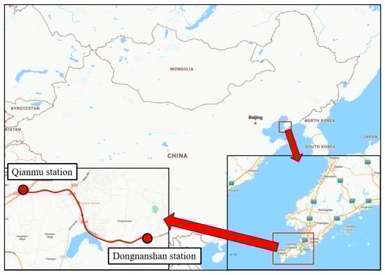
Figure 1.
Geographical location of the project site.
The Qianmu Station to Dongnanshan Station section is located in the western part of the Dalian Metro Line 4 project. The shield machine is launched from the launching shaft behind Qianmu Station, passes under the Heida Line, and proceeds eastward to Dongnanshan Station for retrieval. Two connecting passages (also serving as pump rooms) are planned within this section: No. 2 connecting passage at right line DK8 + 430.000 (left line DK8 + 430.000) and No. 3 connecting passage at right line DK9 + 000.000 (left line DK9 + 000.000).
The longitudinal profile of the shield tunnel section generally forms a “V”-shaped slope. The overburden depth at the crown ranges from 3.2 m to 42.32 m. The strata through which the tunnel structure passes mainly consist of plain fill, highly weathered limestone, and moderately weathered limestone.
The test section is proposed for the right line DK9 + 100~DK9 + 200. The overburden depth in this section ranges from 40.8 m to 48.4 m, with a comprehensive surrounding rock grade of IV. The surface is mountainous terrain, with overlying strata consisting of plain fill (approx. 1.2 m~2.4 m), highly weathered limestone (approx. 1.5 m~10.1 m), and moderately weathered limestone (approx. 28.1 m~45.6 m). According to the Code for Design of Railway Tunnels, this section is classified as a deep-buried section.
3. Test Design
3.1. Specimen Dimensions
To investigate the failure modes and bearing capacity of USFRC segment joints, full-scale USFRC segments with a steel fiber dosage of 40 kg/m3 were used. The steel fiber used in this study was Dramix 4D 80/60 BG, with a diameter of 0.75 mm (see Figure 2). During casting, a steel plate was placed at midspan to divide the segment into two parts for joint formation and curing. The two parts were subsequently connected via bolt holes at both ends (see Figure 3). Compression-bending tests were designed to apply constant eccentricity loading to the segment joints, aiming to study their bearing behavior under actual site loads and verify the safety of USFRC segment joints during installation and operation in the test section. One specimen (DLJ-1) served as the conventional reinforced concrete control, while three identical specimens (DLJ-2, DLJ-3, DLJ-4) were tested to ensure the reliability and repeatability of the results for the new USFRC design. Schematic diagrams of the segment dimensions are shown in Figure 4, with detailed dimensions provided in Table 1.
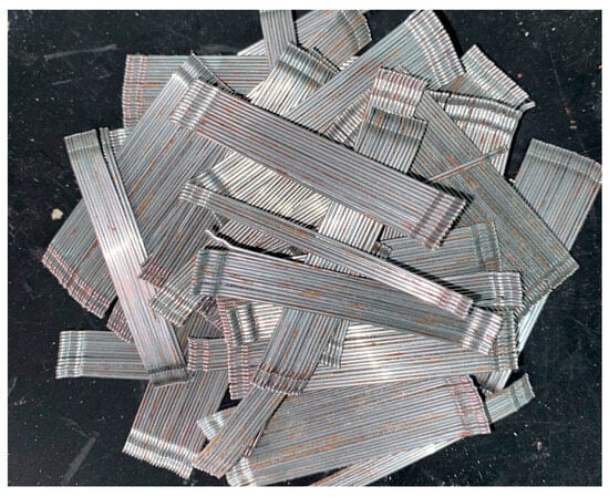
Figure 2.
The Dramix 4D 80/60 BG steel fiber.
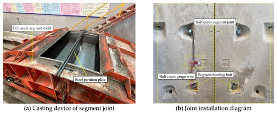
Figure 3.
Schematic diagram of joint casting and installation.
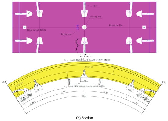
Figure 4.
Schematic diagram of segment size.

Table 1.
Size of specimens.
3.2. Test Conditions
Considering the influence of steel fiber dosage on specimen performance and practical economic factors, USFRC segment joints with a steel fiber dosage of 40 kg/m3 were selected for the compression-bending tests. During the tests, constant eccentricity was maintained as much as possible while applying stepwise loading. Details of the test conditions are provided in Table 2.
Table 2.
Information of test condition.
Figure 5 shows the schematic diagram of the test loading setup. To allow rotational displacement at both ends to counteract bending moments, a specially designed hinge support capable of free rotation was utilized. Vertical loads were applied using two oil-pump jacks with a maximum capacity of 200 tons each. Horizontal loads were applied using four oil-pump jacks with a maximum capacity of 100 tons each. Each jack was connected to a pressure sensor.
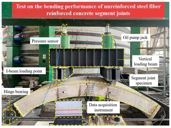
Figure 5.
Schematic diagram of loading device.
During the loading process, the horizontal force is applied at each loading level first. Once the load stabilizes, the vertical force is then applied according to the eccentricity. After each loading level is completed, the load is allowed to stabilize before the monitoring data is read.
3.3. Test Measurement and Calculation Methods
3.3.1. Measurement of Joint Rotation Angle
Horizontal displacement transducers were installed on both the upper and lower sides of the midspan joint (see Figure 6). Data from these transducers were recorded during stepwise loading. The joint rotation angle was calculated using Equations (1)–(3).
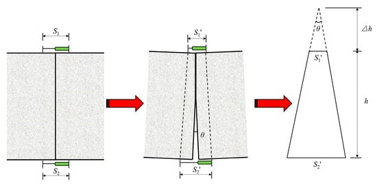
Figure 6.
Calculation model of joint angle.
3.3.2. Calculation of Joint Bending Moment
Taking the section to the left of the midspan joint as a free body (Figure 7), the axial force and bending moment at the midspan joint section were determined based on force equilibrium conditions:
where M is the bending moment at the midspan joint (kN·m), N is the axial force at the midspan joint (kN), P is the single-side vertical load (kN), S is the single-side horizontal load (kN), x is the horizontal distance from midspan to the hinge support at the end (m), x2 is the horizontal distance of the vertical load from midspan (m), G is the self-weight of half a segment (kN), h is the vertical distance from midspan to the hinge support at the end (m), Ns is the bolt tension force (kN), h2 is the vertical distance of the bolt from the hinge support at the end (m), V is the shear force at midspan (kN).
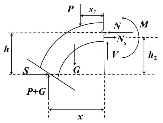
Figure 7.
Analysis diagram of midspan section.
3.3.3. Bolt Force Calculation
Based on literature review [13,14], a bilinear model was adopted for the bolt stress–strain relationship (Figure 8). Before the bolt reaches the yield stress, the bolt stress increases linearly with strain, with the slope being the elastic modulus Es. Once the bolt stress reaches the yield stress σ1, the slope changes, and the bolt stress increases slowly with strain at a rate of 0.01Es until the bolt stress reaches the tensile strength and failure occurs. The joints in this test used M30 ordinary Class 6.8 bent bolts, with a yield strength of 480 MPa, tensile strength of 600 MPa, and stress cross-sectional area of 561 mm2.
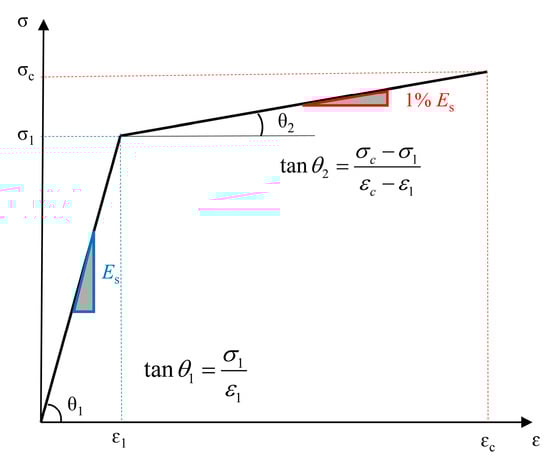
Figure 8.
Stress–strain curve model of bolt.
4. Results
Compression-bending tests were conducted on segment joints DLJ-1 to DLJ-4. The failure states of the joints at the end of the tests are shown in Figure 9.
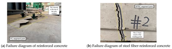
Figure 9.
Failure diagram of segment joints.
4.1. Analysis of Joint Failure Process
Comprehensive analysis of the failure patterns of USFRC (40 kg/m3 dosage) and RC segment joints under compression-bending loading (see Table 3) reveals: (1) The primary failure mode of the RC segment joint is large-area crushing of concrete on the outer curved surface at the top of the joint (see Figure 9a). At this stage, numerous cracks appear on the inner curved surface, but their widths are generally less than 0.20 mm. (2) The primary failure mode of the USFRC segment joint is consistent with that of the full-scale segment, characterized by a 2.50 mm wide tensile crack below the loading point due to excessive bending moment and eccentricity. Almost no compressive cracking failure is observed at the joint. (3) Simultaneously, the bolt strain at crushing failure of the RC segment joint was 8450 μɛ, approximately twice that of the USFRC segment joint at tensile failure. In both cases, the bolts reached yield strain and entered the plastic deformation stage.
Table 3.
Information of test load.
Under positive bending moment, RC and USFRC segment joints exhibit two completely different failure modes, with different failure zones. However, their ultimate bearing capacities are relatively close, with the USFRC joint capacity being slightly higher and exhibiting lower bolt strain. The comparable bearing capacities of RC and USFRC segment joints indicate that USFRC can potentially replace traditional RC under certain conditions.
4.2. Analysis of Bolt Force and Deformation
Figure 10 shows the variation curve of bolt stress with joint bending moment. RC and USFRC segment joint bolt stresses exhibit similar trends: during the joint opening stage, bolt stress increases rapidly with increasing bending moment. After reaching the yield strength, bolt stress increases only slightly with further increase in bending moment, almost negligibly. Bolt stress in the RC segment joint reaches yield strength more readily. For the RC joint, bolt yield occurs at a bending moment of approximately 56.8 kN·m, corresponding to a joint eccentricity of 0.05 m. For the USFRC joint, bolt yield occurs at a bending moment of approximately 74.7 kN·m, corresponding to an eccentricity of 0.07 m. Furthermore, under the same bending moment, the bolt stress in the RC joint is slightly higher than in the USFRC joint. At the final failure stage, the bolt stress in the RC joint was 491.2 MPa (102.3% of yield strength), corresponding to a joint bending moment of 211.3 kN·m and eccentricity of 0.10 m. For the USFRC joint, the bolt stress was 484.9 MPa (101.0% of yield strength), corresponding to a bending moment of 272.5 kN·m and eccentricity of 0.11 m. In summary, USFRC segment joints can effectively control bolt deformation and stress, enabling the joint structure to withstand higher loads and improve its bearing capacity.
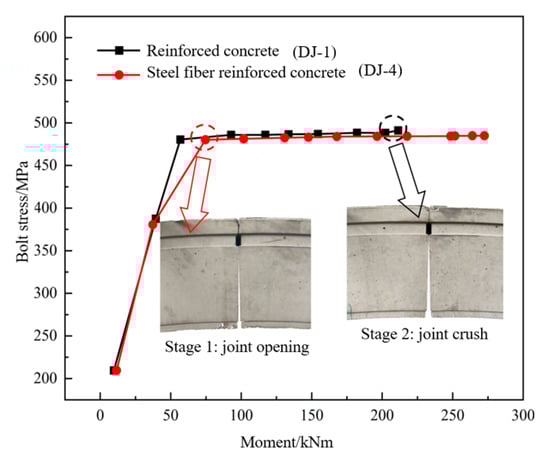
Figure 10.
Bending moment-bolt stress curve.
4.3. Analysis of Joint Rotation Angle and Rotational Stiffness
The rotation angle measurement instrument for joint DLJ-4 was damaged during loading. Figure 11 shows the M-θ curves for joints DLJ-1 to DLJ-3. As can be seen from the figure, under positive bending moment, the M-θ curve of the segment joint follows a bilinear model, roughly divided into two stages. In the first stage, at small bending moments, the joint rotation angle initially increases linearly with a relatively steep slope as the joint gradually opens. As the bending moment increases and the joint opens to a certain extent, the rate of rotation angle change slows down due to the action of the bolts, marking the second stage. Comparing USFRC and RC segment joints, under the same positive bending moment, the rotation angle of the RC joint is significantly larger. In each stage, the slope (stiffness) of the RC joint curve is noticeably smaller than that of the USFRC joint. Before the final loading level, the rotation angle measurement instrument for the RC joint was damaged due to crushing of the top concrete, preventing the recording of the rotation curve at failure. In contrast, the rotation angle of the USFRC segment joint maintained a linear change in the second stage until failure, indicating better ductility and stability of the structure.
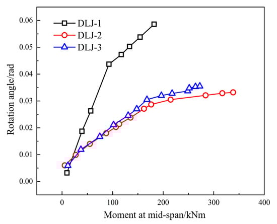
Figure 11.
The M-θ curve of segment joint.
The USFRC segment joint entered the second stage of the rotation curve at a bending moment of approximately 170–175 kN·m. Subsequently, the bolt began to develop plastic strain, and the joint rotation increased linearly at a low rate. The RC segment joint entered the second stage at a bending moment of approximately 100 kN·m, with slopes significantly smaller than those of the USFRC joint in both stages. Rotational stiffness is defined as the bending moment required to produce a unit rotation angle. Based on Figure 11, the rotational stiffness of RC and USFRC segment joints in the two rotation stages can be determined. The rotational stiffness of the RC segment joint in the first stage was approximately 2051.85 kN·m·rad−1, and in the second stage, it was approximately 5993.29 kN·m·rad−1, which is 292.09% of the first stage stiffness. For the USFRC segment joint, the first-stage rotational stiffness was approximately 7533.04 kN·m·rad−1, and the second-stage stiffness was approximately 45,777.78 kN·m·rad−1, which is 607.69% of the first stage stiffness. It is evident that the rotational stiffness of USFRC is significantly higher than that of RC in each stage, indicating a stronger resistance to rotational deformation. Specifically, in the first stage, the rotational stiffness of the USFRC joint is 367.13% of the RC joint, and in the second stage, it is 763.82% of the RC joint. Even at the joint failure stage, the USFRC segment joint structure maintains high load-bearing capacity and deformation resistance.
5. Safety Analysis of Joint Bearing Capacity
5.1. Reinforced Concrete Segment Joint
In Figure 12, a1 is a coefficient taken as 0.80 for concrete strength grades ≤ C50 and 0.74 for C80, with linear interpolation for intermediate grades; fck is the characteristic value of concrete axial compressive strength (MPa); x is the height of the concrete compression zone (m); h is the height of the concrete section (m); Ns is the bolt tension force (kN); Nfu is the section axial force at the ultimate limit state (kN); Mfu is the section bending moment at the ultimate limit state (kN·m); as, as’ are the distances from the resultant points of the longitudinal ordinary reinforcement in the tension and compression zones, respectively, to the corresponding section edge (m); σs, σs’ are the stresses in the longitudinal ordinary reinforcement in the tension and compression zones, respectively (MPa); As, As’ are the stress cross-sectional areas of the longitudinal ordinary reinforcement in the tension and compression zones, respectively (mm2). HRB400 ordinary steel bars with a characteristic yield strength of 400 MPa were used in this specimen. The tension and compression zones were each reinforced with 8 longitudinal bars, giving As = As’ = 2299.65 mm2. The stress–strain curve of the steel bars also followed the bilinear model shown in Figure 10.
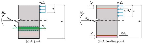
Figure 12.
Calculation model for bearing capacity of reinforced concrete joints.
It can be observed that the error between the experimental and theoretical bearing capacities of RC at the mid-span joint under positive bending moment is small, indicating that the theoretical calculation model can effectively predict the ultimate bearing capacity of RC. Furthermore, the ultimate bearing capacity at the loading point was calculated according to the provisions for eccentric compression bearing capacity of RC sections in Section 6.2.17 of the Code for Design of Concrete Structures [31]. The serviceability limit state bearing capacity (corresponding to a 0.20 mm wide crack) for the RC segment joint used in this test was also calculated and compared with the experimental value (see Figure 13). The relative error is 2.8%, demonstrating that the model in the code is also suitable for calculating the bearing capacity of segment joints, with high accuracy.
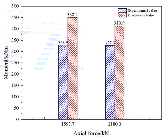
Figure 13.
Comparison of theoretical bearing capacity of reinforced concrete segment joints in ultimate limit states.
5.2. Unreinforced Steel Fiber-Reinforced Concrete Segment Joint
Unlike traditional RC segment joints, the failure mode of USFRC is tensile failure of the concrete below the loading point; no significant crushing phenomenon is observed at the mid-span joint. The bearing capacity calculation model at the USFRC joint location is identical to that for RC. However, at the loading point, besides the absence of steel bars, the steel fibers in the tension zone provide a certain tensile contribution. The tensile force provided by the steel fibers is equivalent to a rectangular stress block. The stress value fftu represents the equivalent tensile strength of SFRC at the ultimate limit state [32]. According to the Technical Specification for Fiber-Reinforced Concrete Structures of Railway Engineering (T/CRS C0701-2021), the equivalent tensile strength of steel fibers must be determined through notched beam tests. During the casting of the segment joints, corresponding cube specimens and notched beam specimens were cast from the same batch. The characteristic axial compressive strength (fck) of both RC and SFRC was determined through cube compressive strength tests. The characteristic equivalent tensile strength standard value (fftuk) of the steel fibers was determined through notched beam tests. The relevant test results are shown in Table 4 and Table 5 and Figure 14 below.
Table 4.
Test results of cube compressive strength test.
Table 5.
Test results of notched beam test.
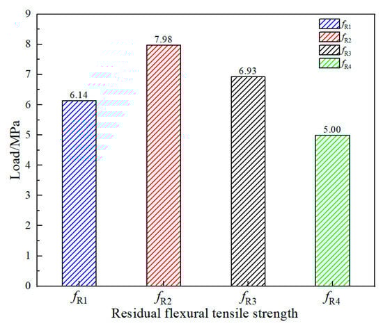
Figure 14.
The residual flexural tensile strength of specimens.
Where fR1, fR2, fR3, fR4 are the residual flexural strengths (MPa) of the notched beam at crack mouth opening displacements (CMOD) of 0.5 mm, 1.5 mm, 2.5 mm, and 3.5 mm (or displacements of 0.47 mm, 1.32 mm, 2.17 mm, and 3.02 mm), respectively. After obtaining the residual flexural strengths, the characteristic residual flexural strength values were calculated using the normal distribution probability statistics method specified in Appendix A.5.2 of the Technical Specification for Steel Fiber-Reinforced Concrete Precast Segments (DB21/T 3165-2019) [33]. The characteristic equivalent rectangular tensile strength of steel fibers at the ultimate limit state (fftuk) was then calculated using the following formulas:
where fRim is the mean residual flexural strength at the corresponding displacement (MPa); ks is the fractile factor, taken as 2.048 as per the code; δc is the coefficient of variation (standard deviation divided by mean) for the corresponding residual flexural strength test values.
After determining the equivalent tensile strength of the steel fibers, the bearing capacity of USFRC under compression-bending load was calculated using a model similar to Figure 12b (see Figure 15).
where β1 is a coefficient taken as 1.00 for concrete strength grades ≤ C50 and 0.94 for C80, with linear interpolation for intermediate grades. The failure mode of the USFRC segment joint is tensile failure of concrete at the loading point (2.50 mm wide crack). Therefore, after obtaining the experimental axial force and bending moment values at the loading point, the corresponding compression zone height x can be solved by substituting the axial force into Equation (8). The theoretical bending moment capacity is then obtained from Equation (9).
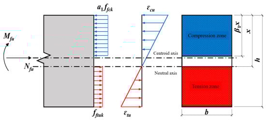
Figure 15.
Calculation model for bearing capacity of unreinforced steel fiber-reinforced concrete.
It can be seen that the experimental bearing capacity of SFRC under positive bending moment is greater than the theoretical design value, with relative errors within 6% (see Figure 16). This indicates that the theoretical calculation model can effectively predict the ultimate bearing capacity of SFRC, providing a small safety margin.
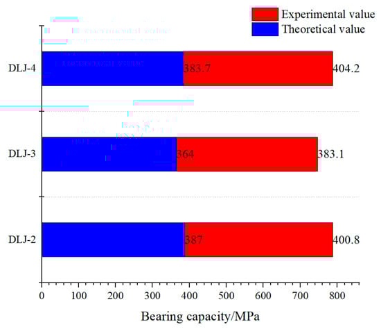
Figure 16.
Comparison of theoretical bearing capacity of steel fiber-reinforced concrete segment joints in ultimate limit states.
5.3. Influence of Bolts on Joint Bearing Capacity
Traditional theoretical bearing capacity calculation models for joints typically consider the tensile force contribution of bolts, assuming it significantly affects the bending capacity. However, analysis of the test results reveals that the actual bearing capacity of the joints aligns more closely with theoretical models that disregard bolt action.
As shown in Figure 13 and Figure 17, the ultimate bearing capacity experimental values for both RC (DLJ-1) and USFRC (DLJ-2~4) segment joints show excellent agreement with theoretical calculation values (relative error ≤ 6%). Notably, these theoretical models are based on force analyses that do not consider the contribution of bolt tension (Figure 12 and Figure 15). This observation contradicts the expectation in traditional models that bolts participate in resisting bending. The bolt shank is placed in a bolt hole with a larger diameter (Figure 3b), leaving a gap between the bolt and the surrounding concrete. During joint opening under bending, the bolt transmits tension only through its end nuts. It does not directly participate in local stress transfer within the concrete compression or tension zones and cannot enhance the concrete’s inherent compressive or tensile strength through friction. However, the significant increase in stiffness after bolt yielding (292.0% for RC, 607.7% for USFRC) demonstrates that the core function of the bolt is to limit joint deformation rather than to provide bending resistance.
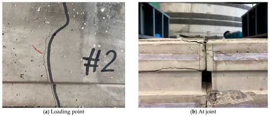
Figure 17.
The damage on the RC segment joint.
5.4. Mechanism of Steel Fibers on Segment Joint Performance
The incorporation of steel fibers significantly alters the failure mode, deformation characteristics, and load-bearing behavior of segment joints. By comparing the mechanical responses of RC and USFRC joints, this test reveals the core mechanisms of steel fibers under compression-bending loads.
5.4.1. Transformation of Failure Mode
The RC segment joint failed through large-area brittle crushing of concrete on the outer curved surface, with only micro-cracks (<0.20 mm) on the inner arc (see Figure 17), indicating premature failure of the compression zone due to insufficient concrete compressive capacity. The USFRC segment joint failed through a 2.50 mm wide tensile crack below the loading point (ductile failure), with no crushing observed (see Figure 18). This demonstrates that steel fibers reconfigure the failure path through the following mechanisms: (1) Fibers bridge cracks, distributing tensile stresses across cracks and delaying crack propagation. (2) Fibers enhance concrete compressive strength while also restraining transverse deformation, increasing the peak strain capacity of the compression zone.

Figure 18.
The damage on the USFRC segment joint.
5.4.2. Stiffness and Deformation Control Capability
Steel fibers significantly increase the joint bending stiffness. The first-stage rotational stiffness increased by 267.1% compared to RC, and the second-stage rotational stiffness increased by 663.5%. The rotation angle at joint failure was reduced by 73% compared to RC. Further analysis of the enhancement mechanism reveals that fibers continuously provide tensile resistance during the plastic deformation stage of concrete, enabling the USFRC segment joint to maintain extremely high stiffness even after bolt yielding. Simultaneously, by increasing stiffness, they interact indirectly with the bolt, preventing it from entering the plastic stage prematurely, thereby enhancing the overall structural load-bearing capacity.
In summary, steel fibers transform joint performance from ‘brittle compression failure’ to ‘ductile tension control’ through a triple mechanism of crack bridging, compression enhancement, and deformation restraint. Their core value lies in enhancing structural toughness rather than merely increasing strength. The USFRC joint, despite eliminating reinforcing bars, achieved a 29% gain in bearing capacity and over 700% increase in stiffness, validating its applicability in high-stress scenarios like shield tunnels.
6. Conclusions and Future Work
Based on the Qiandong experimental section project of Dalian Metro Line 4, this study investigated the failure modes and ultimate bearing capacity of RC and USFRC lining segment joints under compression-bending loading through full-scale laboratory segment joint compression-bending tests. The aim is to provide a reference for the application of USFRC lining segments in domestic underground engineering. The main conclusions are as follows:
- (1)
- The primary failure mode of RC segment joints under compression-bending load with an eccentricity of 0.11 m is large-area crushing of concrete on the outer curved surface, with tensile crack widths on the inner curved surface less than 0.20 mm. The failure mode of USFRC segment joints is characterized by a 2.50 mm wide tensile crack below the loading point, occurring at eccentricities of 0.11~0.13 m.
- (2)
- The bolt strain at failure of RC segment joints is approximately twice that of USFRC joints. Both types reach the yield strength and enter the plastic deformation stage. The bolt stress versus bending moment curve exhibits two stages: rapid growth and slow growth. USFRC can effectively control bolt deformation and stress, improving the load-bearing capacity.
- (3)
- The joint rotation angle versus bending moment curve follows a bilinear model. Under identical bending moments, the rotation angle of RC segment joints is significantly larger than that of USFRC joints. In the first stage, the rotational stiffness of USFRC joints is 367.13% of that of RC joints; in the second stage, it is 763.82% of that of RC joints. At the joint failure stage, the USFRC structure maintains high resistance to deformation.
- (4)
- Bent bolts do not affect the bearing capacity of segment joints. Existing calculation models in current design codes can accurately predict the ultimate bearing capacity of both RC and USFRC segment joints. The relative error for the theoretical failure bearing capacity of RC joints is 5.4%, and for USFRC joints, it is 3.6%, 5.2%, and 5.3%, respectively. The prediction accuracy of the theoretical bearing capacity formulas is high.
In future research, subsequent research will utilize the discrete element software PFC2D 5.0 to model unreinforced steel fiber-reinforced concrete (USFRC), with a focus on its mechanical and durability performance across different fiber dosages, concrete strength grades, and loading conditions. Future work could involve refined numerical simulations of the laboratory tests to better predict the theoretical bearing capacity of segment joints with different dimensions, fiber dosages, and strengths, and to further investigate the stress–strain relationship of bolts. USFRC can, to a certain extent, replace traditional RC. At segment joints, it can effectively reduce rotation deformation and bolt strain. However, attention should be paid to the tensile failure behavior of USFRC. High-dosage USFRC can be used provided the uniformity of fiber distribution and the workability of the concrete mixture are ensured.
Author Contributions
Conceptualization, X.T. and X.R.; methodology, H.X.; formal analysis, X.R.; investigation, J.Z.; resources, Z.W.; funding acquisition, X.T. All authors have read and agreed to the published version of the manuscript.
Funding
This work was supported by Sichuan Natural Science Foundation Youth Fund (Grant No. 2024NSFSC0935), Regional Science and Technology Collaborative Innovation Project of the Science and Technology Department of Xizang (Grant No. QYXTZX-RKZ2023-02), Shigatse Municipal Science and Technology Plan Project: Research on Directional Design of Anti-freeze, Crack-resistant, Low Rebound Sprayed Concrete Considering Xizang Area Environment and Actual Proportioning.
Data Availability Statement
The data presented in this study are available on request from the corresponding author.
Conflicts of Interest
The author Xie Tang was employed by Highway planning, Survey, Design and Research Institute Ltd., the author Xiaohao Rui was employed by Powerchina Huadong Engineering Corporation Ltd. The remaining authors declare that they have no known competing financial interests or personal relationships that could have appeared to influence the work reported in this article.
References
- Zhu, H.; Li, C.; Gao, D.; Yang, L.; Cheng, S. Study on mechanical properties and strength relation between cube and cylinder specimens of steel fiber reinforced concrete. Adv. Mech. Eng. 2019, 11, 1687814019842423. [Google Scholar] [CrossRef]
- Cao, Q.; Gao, Q.; Jia, J.; Gao, R. Early-Age Cracking Resistance of Fiber-Reinforced Expansive Self-Consolidating Concrete. ACI Mater. J. 2019, 116, 15–26. [Google Scholar]
- Bolat, H.; Simsek, O. Evaluation of Energy Absorption of Macro Synthetic and Steel Fiber Reinforced Concretes. Rev. Romana Mater.-Rom. J. Mater. 2015, 45, 123–132. [Google Scholar]
- Nili, M.; Afroughsabet, V. Combined effect of silica fume and steel fibers on the impact resistance and mechanical properties of concrete. Int. J. Impact Eng. 2010, 37, 879–886. [Google Scholar] [CrossRef]
- Feng, K. Research on Mechanical Behavior of Segmental Lining Structure for Underwater Shield Tunnel with Large Cross-Section. Ph.D. Thesis, Southwest Jiaotong University, Chengdu, China, 2012. (In Chinese). [Google Scholar]
- Zhang, H.; Zhang, Z.; Wang, J. 3-D FEM Analysis on Prefabricated Segment Joints of Shield Tunnel. J. Shanghai Jiaotong Univ. 2003, 37, 566–569. (In Chinese) [Google Scholar]
- Zhu, Y.; Zhang, Z.; Zhu, Y. Influence of Different Boundary Conditions on Mechanical Properties of Special-Shaped Shield Segment Joint. Tunn. Constr. 2022, 42, 1003–1013. (In Chinese) [Google Scholar]
- Sun, W.; Jiao, Q.; Xue, G.; Liu, W. Study on Bending Stiffness of No-liner Segment Joint in Shield Tunnel. Chin. J. Undergr. Space Eng. 2008, 4, 973–978. (In Chinese) [Google Scholar]
- Sun, W.; Jiao, Q.; Lan, Y. Research on the Factors Influencing Flexural Rigidity of Duct Piece Joint of Shield Tunnel. J. Railw. Eng. Soc. 2008, 25, 66–71. (In Chinese) [Google Scholar]
- Wu, L. FEM Analysis on Mechanical Behaviors of Segment Joints of Shield Tunnel. Ph.D. Thesis, Southwest Jiaotong University, Chengdu, China, 2005. (In Chinese). [Google Scholar]
- Zhu, W.; Zhong, X.; Qin, J. Mechanical analysis of segment joint of shield tunnel and research on bilinear joint stiffness model. Rock Soil Mech. 2006, 27, 2154–2158. (In Chinese) [Google Scholar]
- Mo, H.; Chen, J.; Liang, S.; Yang, Y.; Su, Y. Improvement of Local Mechanical Properties of Concrete Segment by Steel-Fiber Reinforcement. J. South China Univ. Technol. (Nat. Sci. Ed.) 2007, 35, 116–121. (In Chinese) [Google Scholar]
- Yuan, Q.; Liang, F.; Fang, Y. Numerical simulation and simplified analytical model for the longitudinal joint bending stiffness of a tunnel considering axial force. Struct. Concr. 2021, 22, 3368–3384. [Google Scholar] [CrossRef]
- Zhang, D.; Liu, J.; Li, B.; Zhong, Y. Shearing Behavior of Circumferential Joints with Oblique Bolts in Large Diameter Shield Tunnel. China J. Highw. Transp. 2020, 33, 142–153. (In Chinese) [Google Scholar]
- Zhang, L.; He, C.; Feng, K.; Guo, W.; Zhang, J.; Xiao, M. Influence of Bolts on the Compression-bending Capacity of Segmental Joints of Shield Tunnels. China J. Highw. Transp. 2022, 35, 195–203. (In Chinese) [Google Scholar]
- Gong, C.; Ding, W. Experimental Investigation on Ultimate Bearing Capacity of Steel Fiber Reinforced Concrete Segment Joints in Shield Tunnels. China J. Highw. Transp. 2017, 30, 134–142. (In Chinese) [Google Scholar]
- Naaman, A.E.; Argon, A.S.; Moavenzadeh, F. A fracture model for fiber reinforced cementitious materials. Cem. Concr. Res. 1973, 3, 397–411. [Google Scholar] [CrossRef]
- Olivito, R.S.; Zuccarello, F.A. An experimental study on the tensile strength of steel fiber reinforced concrete. Compos. Part B Eng. 2010, 41, 246–255. [Google Scholar] [CrossRef]
- Thomas, J.; Ramaswamy, A. Mechanical properties of steel fiber-reinforced concrete. J. Mater. Civ. Eng. 2007, 19, 385–392. [Google Scholar] [CrossRef]
- Sloma, S.F. Influence of Hooked-end Steel Fibers on Fresh and Hardened Properties of Steel Fiber Reinforcement Self-Compacting Concrete (SFRSCC). J. Phys. Conf. Ser. 2019, 1198, 032005. [Google Scholar]
- Fuente, A.D.L.; Pujadas, P.; Blanco, A.; Aguado, A. Experiences in Barcelona with the use of fibres in segmental linings. Tunn. Undergr. Space Technol. 2012, 27, 60–71. [Google Scholar] [CrossRef]
- Qi, M.S.; Liu, X. A Full-scale Experimental Study on Bearing Capacity of Fiber Reinforced Concrete Segments. Chin. J. Undergr. Space Eng. 2019, 15, 55–60. (In Chinese) [Google Scholar]
- Liu, X.; Sun, Q.H.; Jiang, H.; Bao, H.L. Experimental Research and Theoretical Analysis of Mechanical Behaviors of Fiber Reinforced Concrete Segments. Mod. Tunn. Technol. 2018, 55, 1080–1090. (In Chinese) [Google Scholar] [CrossRef]
- Liu, X.; Sun, Q.; Yuan, Y.; Taerwe, L. Comparison of the structural behavior of reinforced concrete tunnel segments with steel fiber and synthetic fiber addition. Tunn. Undergr. Space Technol. 2020, 103, 103506. [Google Scholar] [CrossRef]
- Xu, H.Y.; Wang, Z.J.; Zhou, P.; Li, Z.Y.; Xu, J.X.; Tang, L.; Li, R.Y. Eccentric compression model test of steel fiber reinforced concrete lining segments. J. Build. Struct. 2018, 39, 290–298. (In Chinese) [Google Scholar] [CrossRef]
- Oh, B.H. Flexural Analysis of Reinforced Concrete Beams Containing Steel Fibers. J. Struct. Eng. 1991, 118, 2821–2835. [Google Scholar] [CrossRef]
- Yang, I.H.; Joh, C.; Kim, B.S. Structural behavior of ultra high performance concrete beams subjected to bending. Eng. Struct. 2010, 32, 3478–3487. [Google Scholar] [CrossRef]
- Mertol, H.C.; Baran, E.; Bello, H.J. Flexural behavior of lightly and heavily reinforced steel fiber concrete beams. Constr. Build. Mater. 2015, 98, 185–193. [Google Scholar] [CrossRef]
- Yoo, D.Y.; Yoon, Y.S. Structural performance of ultra-high-performance concrete beams with different steel fibers. Eng. Struct. 2015, 102, 409–423. [Google Scholar] [CrossRef]
- Biolzi, L.; Cattaneo, S. Response of steel fiber reinforced high strength concrete beams: Experiments and code predictions. Cem. Concr. Comp. 2017, 77, 1–13. [Google Scholar] [CrossRef]
- T/CRS C0701-2021; Technical Specification for Fiber Reinforced Concrete Structures of Railway Engineering. China Railway Publishing House: Beijing, China, 2021. (In Chinese)
- GB 50010-2010; Code for Design of Concrete Structures (2015 Edition). China Architecture & Building Press: Beijing, China, 2016.
- DB21/T 3165-2019; Technical Specification for Steel Fiber-Reinforced Concrete Precast Segments. Liaoning Provincial Administration for Market Regulation: Shenyang, China, 2019.
Disclaimer/Publisher’s Note: The statements, opinions and data contained in all publications are solely those of the individual author(s) and contributor(s) and not of MDPI and/or the editor(s). MDPI and/or the editor(s) disclaim responsibility for any injury to people or property resulting from any ideas, methods, instructions or products referred to in the content. |
© 2025 by the authors. Licensee MDPI, Basel, Switzerland. This article is an open access article distributed under the terms and conditions of the Creative Commons Attribution (CC BY) license (https://creativecommons.org/licenses/by/4.0/).