Abstract
Corrosion in reinforced concrete (RC) structures increases seismic fragility by reducing strength, ductility, and bond integrity, which becomes critical in aging infrastructure. This study provides a systematic fragility comparison of intact, corroded, and FRP-strengthened structures across multiple corrosion levels under sequential earthquakes. The seismic fragility of corroded RC frames, with and without fiber-reinforced polymer (FRP) retrofitting, is investigated under both mainshock and aftershock loading conditions. A total of 508 real recorded mainshock–aftershock ground motion sequences are selected as seismic inputs to ensure the representation of earthquake demands. Nonlinear time history analyses are carried out to establish fragility curves for four limit states based on probabilistic demand–capacity relationships. The results show that corrosion significantly decreases the collapse prevention capacity (LS4), with the maximum reduction reaching about 62%. FRP retrofitting restores seismic performance to varying degrees depending on corrosion severity. For the structure with a 10% corrosion rate, FRP retrofitting enhances the collapse capacity beyond that of the intact case. For the structure with a 20% corrosion rate, FRP retrofitting recovers approximately two-thirds of the lost capacity caused by reduced ductility. The consideration of aftershock effects further increases the fragility of corroded structures, yet FRP retrofitting continues to provide improvement by reducing cumulative damage and improving deformation capacity. The study confirms that the FRP confinement effectively enhances the seismic resilience of aging RC structures and provides a practical basis for performance-based retrofit strategies under sequential earthquake events.
1. Introduction
The seismic safety of aging reinforced concrete (RC) infrastructure has become a growing concern in earthquake-prone regions [1,2]. Many existing RC buildings are constructed before the latest modern seismic and durability codes or guidelines. As these structures age, corrosion of reinforcing steel progressively weakens their mechanical properties [3,4]. When combined with the demands induced by earthquake loading, including both mainshock and aftershock events, corrosion can severely elevate the risk of structural failure, particularly during strong ground motions.
The corrosion effect alters the load-resisting mechanism of RC members through several interrelated processes. The loss of rebar cross-section directly reduces flexural and shear capacity, while the expansive corrosion products induce cracking and spalling of the cover concrete [5,6]. These cracks not only accelerate further corrosion but also diminish the confinement of the core concrete and reduce bond strength between steel and concrete [7]. Under cyclic loading, the weakened bond and reduced confinement cause early rebar slip and rapid stiffness degradation, leading to significant reductions in lateral strength and ultimate drift. Experimental investigations have consistently reported that even moderate corrosion, about 10–20% section loss, can reduce lateral capacity by 40–60% [8,9]. Consequently, the seismic fragility of corroded RC structures increases substantially even when corrosion damage remains moderate [10].
In earthquake events, the performance of RC structures is further affected by the occurrence of aftershocks. While the mainshock produces the primary damage condition, aftershocks can cause additional damage to already damaged structures [11]. These additional earthquake events intensify the cyclic degradation of the materials, increasing the failure risk of corroded components. The cumulative effect of mainshock–aftershock loading is particularly damaging to corroded RC structures, as the residual strength and deformation capacity are already compromised due to the corrosion-induced degradation [12,13]. In particular, aftershocks contribute to the acceleration of cracking and stiffness degradation, further increasing the risk of collapse.
To mitigate the deterioration caused by corrosion and improve the seismic performance of the aging structures, fiber-reinforced polymer (FRP) composites have been increasingly adopted as a retrofit solution for RC structures. FRP can significantly enhance structural strength by carrying a portion of the tensile load and delaying cover spalling through lateral confinement [14,15]. Compared to traditional retrofitting techniques [16], such as steel jacketing, FRP offers several advantages, including ease of application, light weight installation, and resistance to corrosion [17,18,19,20,21]. Previous studies have demonstrated that FRP confinement improves both strength and ductility, thereby enhancing the seismic resilience of RC members [22,23]. However, the effectiveness of FRP retrofitting is highly dependent on the condition of the corroded substrate. Severe corrosion often results in microcracking and surface roughness, which compromise the bond between the FRP and the concrete, limiting the potential for effective stress transfer and reducing overall retrofit performance.
Seismic fragility analysis has become a powerful framework for quantifying uncertainties. By expressing the probability of exceeding specific damage states as a function of ground motion intensity, fragility curves provide a direct link between material degradation, structural response, and seismic risk. Recent studies have emphasized that fragility-based methods allow for a more comprehensive comparison of retrofit strategies and corrosion scenarios [24]. Analytical frameworks implemented in OpenSees and similar platforms enable the investigation of nonlinear hysteresis, cyclic degradation, and bond–slip effects within a probabilistic context, thereby bridging the gap between component-level degradation and system-level seismic performance [25,26]. Previous research has been conducted to explore the seismic fragility of either corroded or FRP-retrofitted RC structures. Studies focusing on corrosion-induced deterioration have demonstrated that reinforcement corrosion substantially reduces both the lateral load capacity and ductility of RC columns [27]. The earthquake intensity at the collapse limit state is shown to decrease almost linearly with the percentage of steel cross-section loss, while the dispersion of fragility curves tends to increase, reflecting higher uncertainty in post-yield performance. These studies further reveal that corrosion accelerates stiffness and strength degradation under cyclic loading, leading to steeper fragility slopes and narrower safety margins between damage states [28,29]. In parallel, several studies have examined FRP strengthening in enhancing the seismic resilience of uncorroded or mildly deteriorated RC members. Experimental studies and analytical models have revealed that FRP confinement and external reinforcement can obviously improve deformation capacity, delay cover spalling, and enhance hysteretic energy dissipation [30,31]. Analytical fragility studies for FRP-strengthened RC frames have further indicated notable reductions in collapse probability and inter-story drift demands under strong ground motions [32].
In summary, there remains a gap in understanding the combined effects of corrosion and aftershock loading on the seismic fragility of FRP-retrofitted RC structures. Although the individual effects of corrosion-induced degradation and FRP strengthening have been extensively studied, research that simultaneously considers both mechanisms remains limited. More importantly, investigations on the influence of different corrosion levels and FRP retrofitting strategies on seismic fragility under combined mainshock–aftershock loading are still limited. The cumulative deterioration caused by sequential earthquakes highlights the need for such integrated assessments. To capture a range of moderate deterioration in service-age RC buildings, this study considers two average reinforcement corrosion rate scenarios—10% and 20%—which correspond to the lower-to-mid range of “moderate” corrosion reported in field and laboratory surveys. These values are selected under three considerations: (I) they are frequently observed in chloride-exposed and carbonation-affected reinforced concrete in service for several decades; (II) they produce measurable reductions in flexural and bond capacity without complete loss of member functionality; and (III) they allow investigation of performance trends that are practically relevant for retrofit decision-making.
This study aims to provide a comprehensive fragility-based analysis of the seismic performance of corroded RC structures, with and without FRP strengthening. The analysis is conducted using a representative multi-story RC frame building modeled in OpenSees. A set of mainshock and aftershocks is selected as the seismic input. Corrosion effects are introduced by reducing steel and concrete parameters, while FRP strengthening is represented through equivalent stress–strain enhancements in confinement and tension. The resulting fragility curves are compared across the following five cases: (1) intact, (2) 10% corrosion, (3) 20% corrosion, (4) 10% corrosion + FRP, and (5) 20% corrosion + FRP. The remainder of this paper is organized as follows. Section 2 presents the structural model, material constitutive relationships, and FRP modeling approach. Section 3 outlines the selection of mainshock and aftershock ground motions in this study. Section 4 provides the development of seismic demands and fragilities. Section 5 discusses the results of fragilities, including overall trends, degradation mechanisms, and retrofit efficiency. Finally, Section 6 draws conclusions of this paper.
2. Numerical Modeling of Case Building
2.1. Structural Details
In this study, a seven-story, three-span RC frame structure is selected as the case building. The structure is designed and verified in accordance with current Chinese seismic design codes [33]. The design process is carried out using the PKPM (Version 2020) structural analysis software to ensure that both global- and component-level performance meet code requirements. Furthermore, the detailed design is reviewed and validated by professional structural engineers to guarantee the rationality and engineering applicability of the model. The building is assumed to function as an office building. Each story has a uniform height of 3.6 m, and the span length of the frame is 7.2 m. The floor plan and elevation of the structural layout are illustrated in Figure 1.
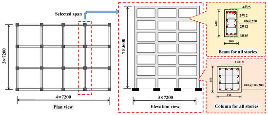
Figure 1.
Design information of the case building.
According to the design specifications, the building has a seismic fortification intensity of 7 degrees, corresponding to a peak ground acceleration (PGA) of 0.1 g. The site category is classified as Type II, and the seismic design group is Group I. Type II represents medium-stiff soil conditions characterized by moderate shear wave velocity. It corresponds to typical urban construction sites with layered soil profiles that are neither soft nor rock-like. The dead and live loads on each floor are both taken as 2 kN/m2, while the roof dead and live loads are 4 kN/m2 and 0.5 kN/m2, respectively. The snow load and wind pressure are 0.5 kN/m2 and 0.75 kN/m2, respectively. The design strength of concrete is C40, and the reinforcement steel grade is HRB400E. The column cross-section is 650 mm × 650 mm, with stirrups of 10 mm diameter. Based on the stirrup confinement requirements, each column is divided into two regions: a stirrup-densified region and a non-densified region. The densified regions are located at both ends of the column, each with a length of 600 mm and a stirrup spacing of 100 mm, while the middle region has a spacing of 200 mm. The beam cross-section is 300 mm × 600 mm, reinforced with 8 mm diameter stirrups. All beam and column members have a concrete cover thickness of 30 mm. The rationale for using a uniform column section is that the original design of the case building (an office-type, regularly arranged frame) adopted identical column and beam dimensions for simplicity and constructability. The detailed reinforcement configurations of the beams and columns are also shown in Figure 1.
The seven-story, three-span RC moment-resisting frame is highly representative of typical medium-rise office buildings widely found in seismic regions of China. The story height, span arrangement, and column dimensions are consistent with common design practices of existing RC frames constructed during the past two decades. Moreover, its regular structural configuration and moderate height make it suitable for investigating mainshock–aftershock fragility behavior without the additional complexity introduced by irregularity or high-rise dynamic characteristics. These considerations render the selected structure an appropriate and representative case for evaluating the influence of corrosion and FRP strengthening under sequential earthquake excitations.
2.2. Corroded and FRP-Retrofitted Structures
Based on the aforementioned case building, five structural models are further established to account for different corrosion and retrofitting conditions, denoted as Structure-1 to Structure-5. Among them, Structure-1 represents the intact (no corrosion damage) structure. Structure-2 and Structure-3 correspond to corroded structures with average reinforcement corrosion rates of 10% and 20%, respectively, in order to evaluate the degradation effect of different corrosion levels on structural performance. Structure-4 and Structure-5 represent the different corrosion levels (10% and 20%) but strengthened with FRP, aiming to investigate the effectiveness of FRP retrofitting in improving the seismic performance of corroded RC frames [34].
The retrofitting scheme involves wrapping three layers of FRP around the potential plastic hinge zones of beams and columns at all floors to enhance their ductility and energy dissipation capacity. According to the current Chinese strengthening codes (GB 50608-2020) [35], structural members such as beams and columns are required to be retrofitted with no fewer than three layers of FRP sheets when confinement-type strengthening is applied. A retrofit range of 700 mm is selected for both beams and columns, determined according to existing empirical models for the plastic hinge length of RC components. This range adequately covers the critical deformation region while maintaining material efficiency and cost-effectiveness. The schematic diagrams of the retrofitting configuration are shown in Figure 2. In this study, a unidirectional carbon fiber-reinforced polymer (CFRP) fabric is adopted as the strengthening material, with an areal density of 200 g/m2 and a nominal thickness of 0.111 mm per layer. The CFRP fabric possesses an elastic modulus of 240 GPa, an ultimate tensile strength of 3200 MPa, and an ultimate tensile strain of 0.012. These material properties are representative of commonly used CFRP fabrics in engineering applications and are suitable for reflecting the strengthening effects of FRP on the seismic performance of corroded RC frame structures [36].
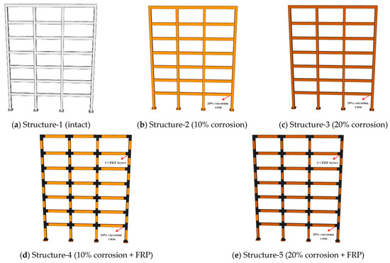
Figure 2.
The five structural models in this study.
2.3. Finite Element Model
A finite element (FE) model of the case study RC frame structure is developed using the OpenSees platform (Version 3.7). In the finite element model, each structural component is represented through a combination of elastic elements and nonlinear rotational springs to capture both geometric and material nonlinearities. The beams and columns are modeled using elastic beam–column elements, which reproduce the elastic flexural, shear, and axial deformation of the members and preserve the global stiffness and load-transfer characteristics of the frame. The nonlinear material behavior is concentrated in zero-length rotational springs formulated with the modified Ibarra–Medina–Krawinkler (I-M-K) hysteretic model [37]. These springs are assigned at the ends of beams and columns to reproduce strength deterioration, stiffness degradation, cyclic pinching, and post-capping behavior, enabling realistic simulation of plastic hinge response under mainshock and aftershock excitations [38]. The global P-Δ effect is modeled using a leaning column that carries the gravity loads of the structure. To allow this leaning column to develop the correct second-order moment amplification without contributing flexural stiffness, a rotational spring with small stiffness is placed at its base to provide the necessary rotational degree of freedom. The leaning column is connected to the main frame through truss elements, which transfer only axial force and thus ensure that the P-Δ effect is represented without influencing the lateral stiffness of the primary structural system [4]. The overall finite element configuration of the structure is illustrated in Figure 3. The peak-oriented modified I-M-K model is shown in Figure 4.
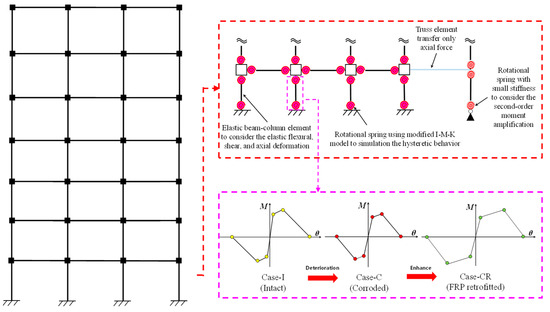
Figure 3.
Finite element model of the structures.
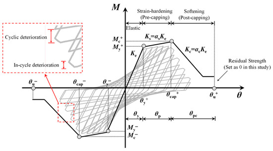
Figure 4.
The peak-oriented modified Ibarra–Medina–Krawinkler (I-M-K) model.
For the intact structure, the model parameters of beams and columns are calibrated using the empirical relationships proposed by Haselton and Deierlein [39]. The parameters for the corroded and FRP-strengthened corroded structures are subsequently derived through parameter modification based on the intact model. Specifically, the parameters of the corroded members are obtained by multiplying the intact component parameters by the corrosion-induced deterioration coefficients (CIDCs), whereas those of the FRP-strengthened corroded members are further adjusted by applying the hybrid influence factors (HIFs) [40] to account for the combined effects of corrosion degradation and FRP confinement. The corresponding adjustment equations for CIDCs and HIFs are summarized in Table 1. Meanwhile, the cyclic deterioration parameters are modified following the same relationships to ensure that the FRP-retrofitted corroded components can reflect the restored ductility and energy dissipation capacity after strengthening. This modeling framework enables a consistent representation of the nonlinear response of RC members under different corrosion and strengthening conditions, providing a robust basis for the subsequent seismic performance and fragility analyses.

Table 1.
Equations to calculate the modified I-M-K parameters for corroded and FRP-retrofitted members.
Corrosion-induced deterioration in reinforcing steel and concrete tends to reduce member stiffness, which can increase global structural flexibility and the fundamental period. Conversely, FRP confinement contributes to stiffness recovery and tends to reduce the fundamental period. For the present case study frame, these effects are evaluated and found to be of limited magnitude relative to the overall dynamic response and the objectives of the fragility assessment. Therefore, model-property changes are not discussed in detail in this paper.
2.4. Model Validation
To evaluate the effectiveness of the corrosion-induced deterioration coefficients (CIDCs) and the hybrid influence factors (HIFs) summarized in Table 1 for modifying the I-M-K hysteretic model, a comprehensive model validation is conducted using multiple sets of publicly available experimental data. First, the applicability of the CIDC formulation is examined using the C-5 specimen tested by Zheng et al. [41] and the Z4 specimen tested by Xia [42]. These two specimens exhibit longitudinal reinforcement corrosion rates of 2.4% and 14.2%, respectively, with an identical axial load ratio of 0.40. Based on their geometric properties, reinforcement details, and measured corrosion damage, numerical models incorporating CIDC-modified I-M-K parameters are constructed, and the predicted hysteretic responses are compared with the experimental curves, as illustrated in Figure 5. The model successfully reproduces the characteristic degradation features of corroded RC columns—including peak strength reduction, ductility loss, and progressive stiffness deterioration. The predicted skeleton curves, hysteretic envelopes, and degradation trends align closely with the measured responses, demonstrating that the CIDC formulation can capture the influence of reinforcement corrosion on the hysteretic behavior of RC members.
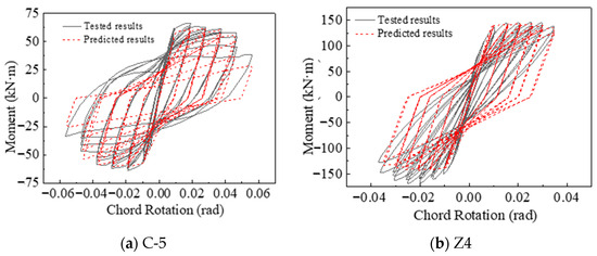
Figure 5.
Tested and predicted hysteretic curves for corroded specimens.
Furthermore, the applicability of the HIF model for FRP-retrofitted corroded columns is validated using the C-10-L1PET-N02 and C-20-L1PET-N02 specimens tested by Lao [43] (with corrosion ratios of 7.8% and 15.3%, and axial load ratios of 0.17 and 0.169, respectively), as well as the CF20 specimen tested by Karimipour and Edalati [44] (corrosion ratio 9.8%, axial load ratio 0.10). These specimens are externally strengthened using one layer of PET sheet, one layer of PET sheet, and three layers of CFRP sheets, respectively. As shown in Figure 6, the HIF-adjusted hysteretic model captures the strength recovery, ductility enhancement, and improved energy dissipation observed in the tests. The predicted hysteretic envelope shapes, strength enhancement levels, and cyclic degradation characteristics exhibit close agreement with the experimental results, confirming the accuracy and applicability of the HIF formulation for simulating the hysteretic response of FRP-retrofitted corroded RC columns.

Figure 6.
Tested and predicted hysteretic curves for FRP-retrofitted corroded specimens.
To further validate the finite element model at the structural system level, the predicted hysteretic responses of the first-story exterior columns in Structure-1 (intact), Structure-3 (20% corrosion), and Structure-5 (20% corrosion + FRP retrofit) are compared, as presented in Figure 7. The corresponding moment–rotation values at key response points are also provided in the figure. The results indicate that Structure-3 exhibits pronounced strength degradation, reduced ductility, and significant stiffness deterioration compared with Structure-1, fully reflecting the detrimental effects of moderate corrosion on seismic performance. In contrast, Structure-5 shows considerable strength restoration and stiffness improvement under the same loading conditions. The hysteretic envelope is fuller, with markedly enhanced energy dissipation capacity, demonstrating that FRP confinement can effectively compensate for the loss of strength and deformation capacity caused by corrosion. In summary, at both the component and system levels, the I-M-K hysteretic model modified using the CIDC and HIF formulations is capable of reproducing the behaviors of corroded RC members and FRP-retrofitted corroded members. These results confirm that the proposed modeling framework can capture the coupled effects of corrosion, degradation, and strengthening, thereby providing a robust basis for the subsequent seismic fragility analysis.
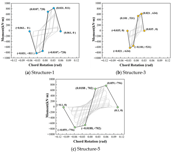
Figure 7.
Predicted hysteretic curves for first-story exterior columns.
We acknowledge the potential impact of uncertainties, including variability in corrosion patterns, FRP–concrete interface behavior, and hysteretic parameters of the I-M-K model, which could result in a variation in seismic behavior. However, addressing these modeling uncertainties in detail is beyond the scope of this paper.
3. Selection of Seismic Input
To make the seismic fragility analysis more realistic, this study uses recorded mainshock–aftershock ground motion sequences as the input motions. The use of real sequences allows for a more realistic simulation of cumulative structural damage under successive mainshock and aftershock excitations. The ground motion data are obtained from the PEER strong motion database [45] and selected following the criteria proposed in Reference [46]. The selection procedure is summarized as follows:
(1) Ground motions that are recorded at the same station and occur within a short time interval are grouped together to ensure consistent site conditions and recording settings.
(2) In each group, the earthquake with the largest magnitude is identified as the mainshock, and the record is then removed from the dataset.
(3) Then, the aftershock with the largest magnitude within the same group is selected as the corresponding aftershock, forming a paired mainshock–aftershock sequence.
Following this selection process, a total of 506 mainshock–aftershock ground motion pairs are obtained and used for subsequent seismic fragility analyses. These records are used directly for cloud analysis to preserve the natural spectral characteristics and intensity levels of the events. The response spectra of the selected mainshock and aftershock motions are presented in Figure 8a,b. To verify the validity of the selected records, statistical analyses of their response spectra and magnitude–epicentral distance distributions are conducted, as shown in Figure 8c,d. The results indicate that the magnitudes of mainshocks are consistently higher than those of aftershocks, and the median response spectra of mainshocks exceed those of aftershocks, which agrees well with the general characteristics of real mainshock–aftershock events.
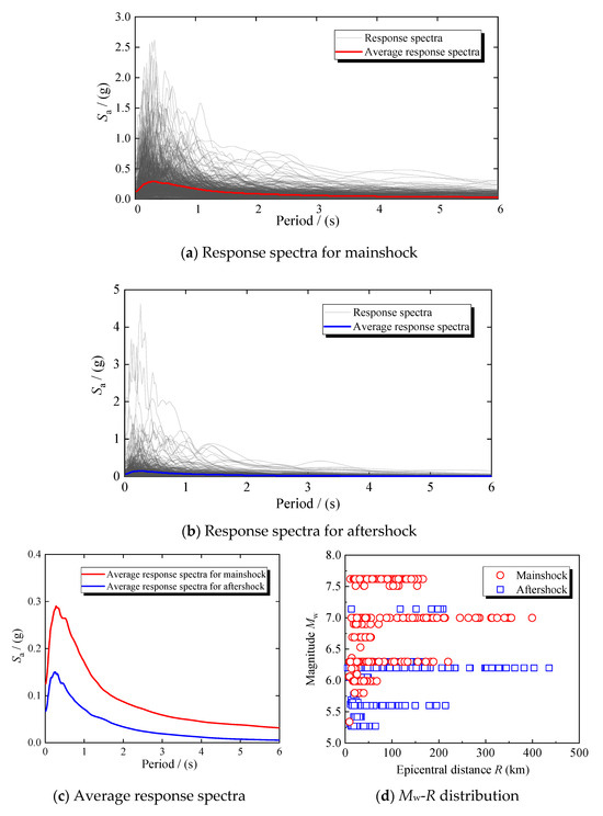
Figure 8.
Selected mainshock and aftershock seismic inputs.
After that, to better represent the actual temporal sequence of earthquake events, a time interval of 60 s is inserted between the mainshock and aftershock records during sequence construction [11] (see Figure 9). This interval allows the structure to experience free vibration and energy dissipation following the mainshock, ensuring that it enters the aftershock in a partially damaged state. Such modeling more accurately reflects the progressive damage mechanism under consecutive seismic actions. The resulting mainshock–aftershock sequences can capture both the dominant destructive effect of the mainshock and the cumulative degradation induced by the aftershock.
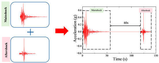
Figure 9.
Construction of mainshock–aftershock ground motion sequences.
While the mainshock magnitudes exceed those of the aftershocks, the intensity ratio between the paired records is not systematically characterized. However, the use of real event records inherently captures this intensity variation, and the focus of this study is on the sequence of loading. The influence of absolute magnitude difference is out of the scope of this paper. In addition, it should be noted that while the selected mainshock–aftershock sequences reflect a broad range of real earthquake events, the representativeness of these ground motions relative to the target hazard is not assessed in this study.
4. Seismic Fragility Assessment for Case Buildings
4.1. Method Overview
A probabilistic seismic demand model-based methodology is adopted to develop fragility curves for the RC structures subjected to varying levels of corrosion and strengthened with FRP composites. Four global limit states (LS1–LS4) are defined based on the Park–Ang damage model [47].
- ➢
- LS1 (Slight damage) with D = 0.1;
- ➢
- LS2 (Moderate damage) with D = 0.2;
- ➢
- LS3 (Severe damage) with D = 0.5;
- ➢
- LS4 (Collapse) with D = 1.0.
Here, D represents the damage index of the corresponding limit states. The spectral acceleration (Sa) is employed as the earthquake intensity measure (IM). The damage thresholds used in the fragility analysis (0.1, 0.2, 0.5, 1.0) are based on values commonly applied in the literature for typical RC structures under seismic loading. For collapse (LS4, D = 1.0), we acknowledge that this threshold defines complete failure or instability under idealized conditions. Future work could explore the effects of different collapse criteria to corroded or FRP-strengthened structures. While additional structural response metrics such as peak drift, residual drift, and hinge distributions are valuable for understanding the detailed behavior of a structure, they are not the focus of this study. The primary goal is to evaluate the effects of corrosion and FRP retrofitting on seismic fragility, and the results are presented in terms of fragilities and probability of failure.
We acknowledge that the Park–Ang damage index is primarily developed for intact RC members. The fragility estimates are sensitive to the assumed thresholds for damage progression. The progression of damage in corroded or FRP-strengthened members may differ significantly. While this study uses the standard thresholds for the damage index, future research could focus on refining the model to account for different damage behaviors in these members.
4.2. Development of Seismic Demand Models
For each structural configuration (Structure-1 to Sturcture-5), the cloud method is developed by plotting the D against the Sa. For each structural configuration and each damage measure (D), a log-linear regression model for mainshock-only and mainshock–aftershock scenarios is established in the following form [48]:
where αM1 represents the regression intercept of the mainshock, and αM2 is the regression slope of the mainshock, quantifying the rate of increase in demand with intensity.
where αMA1 represents the regression intercept of the mainshock; αMA2 is the regression slope of the mainshock, quantifying the rate of increase in demand with mainshock intensity; and αMA3 is the regression slope of the aftershock, quantifying the rate of increase in demand with aftershock intensity.
In the time history simulations, corroded members exhibited a rapid stiffness degradation and larger residual drifts following the mainshock compared to intact cases. The additional cyclic loading from aftershocks exacerbated these effects, leading to earlier bond–slip and propagation of microcracks at the FRP–concrete interface in retrofitted members. The regression is performed separately for each corrosion/retrofit case (see Figure 10 and Figure 11), using least-squares fitting on the logarithmic data. The coefficient of determination (R2) is maintained above 0.7 for all models, indicating strong correlation between structural damage and ground motion intensities.
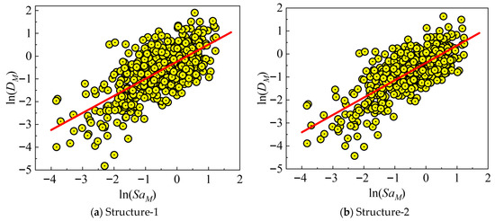
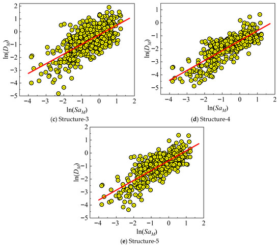
Figure 10.
Demand models of mainshock for each building.
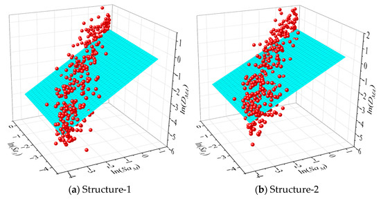
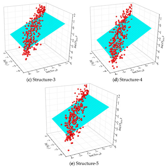
Figure 11.
Demand models of mainshock and aftershock for each building.
4.3. Fragility Functions
The fragility functions are developed to quantify the probability of a structure reaching or exceeding a specific damage state under a given level of seismic intensity. Based on the results of the demand models, the total dispersion parameter β is determined as the standard deviation of the logarithmic differences between the observed and predicted demands, incorporating the variability of both the structural demand ln(D) and capacity ln(C) from the regression analysis. The fragility function is formulated as a lognormal cumulative distribution [25], expressed as follows:
where C represents the seismic capacity of the structure, β is the logarithmic standard deviation (total dispersion), and Φ(⋅) represents the standard normal cumulative distribution function.
To reflect the inherent randomness of materials and modeling, the capacity thresholds for the four limit states follow a lognormal distribution with median values of 0.1, 0.2, 0.5, and 1.0, and a logarithmic standard deviation of 0.25. The fragility curves for the five cases are shown in Figure 12 for both the mainshock-only and mainshock–aftershock scenarios.
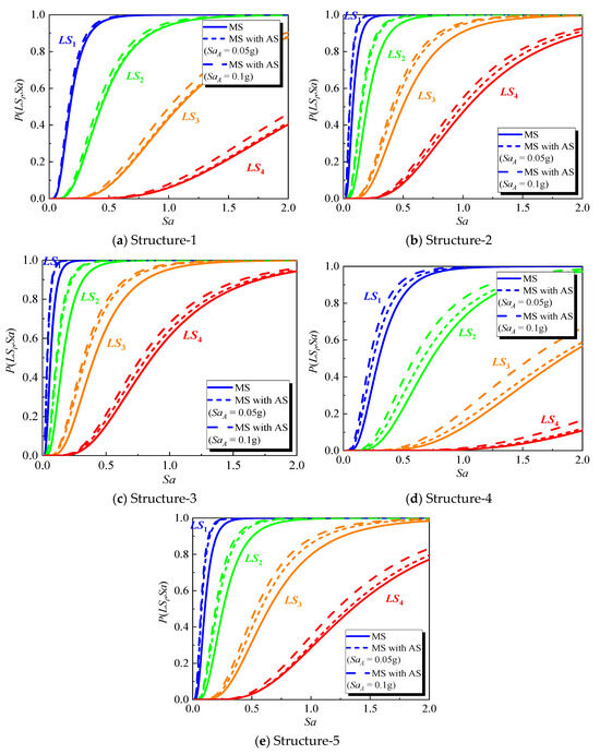
Figure 12.
Fragility curves of case structures.
The derived fragility curves reveal a clear trend across all case structures, both under mainshock-only loading and combined mainshock–aftershock loading. As corrosion progresses, the fragilities shift toward lower intensity measures, indicating a reduction in seismic capacity and an increased probability of exceeding each damage state under the same ground motion intensity. For the mainshock-only case, the 10% corrosion scenario exhibits moderate degradation, while the case structure with 20% corrosion ratio shows a larger leftward displacement of the fragility curves, reflecting significant losses in both strength and ductility. When aftershocks are included, the fragility curves for corroded structures shift further leftward compared to the mainshock-only case. Specifically, aftershock loading (at 0.05 g and 0.1 g) exacerbates the deterioration of the structure, further reducing its seismic resistance, especially at higher damage states (LS3 and LS4). The additional cyclic loading from aftershocks accelerates concrete cracking, increases stiffness degradation, and enhances the effects of bond–slip between the reinforcement and concrete, which contributes to more rapid failure.
Conversely, FRP retrofitting can effectively counteract the adverse shift, both for mainshock and aftershock loading conditions. For corroded structures strengthened with FRP, the fragilities corresponding to all damage states decrease relative to their un-strengthened cases, demonstrating a recovery in seismic resistance. The improvement is particularly noticeable at higher damage states (LS3 and LS4). While FRP strengthening remains effective even under aftershock loading, the improvement is reduced compared to the mainshock-only case, reflecting the additional damage induced by the aftershocks. For more severely corroded structures (20% corrosion), the effectiveness of FRP in recovering seismic performance is partially diminished under aftershock conditions.
In general, the results of the fragility curves show a progressive deterioration of seismic performance with corrosion, which is further aggravated by aftershocks. However, FRP strengthening can partially or fully restore the seismic resilience of corroded structures, with the degree of restoration depending on the corrosion severity and the intensity of aftershock loading.
5. Discussions
5.1. Overall Trends in Seismic Fragility Medians with Aftershocks
To provide a more detailed comparison of seismic fragilities, the median spectral accelerations corresponding to a 50% probability of exceeding each damage state (Sa50) are calculated for all structural configurations, as shown in Figure 13. These median fragilities present clear and physically interpretable trends in the seismic performance of intact, corroded, and FRP-strengthened RC structures. As expected, the inclusion of aftershocks results in a noticeable reduction in the seismic capacity of all structures. This reduction is particularly significant for corroded and un-strengthened structures compared with the intact and FRP-retrofitted cases. The primary reason is that aftershocks further accelerate the deterioration of corroded members, including bond–slip, stiffness degradation, and crack propagation. These effects become more critical at higher damage states, where the residual capacity of the structure is already limited.
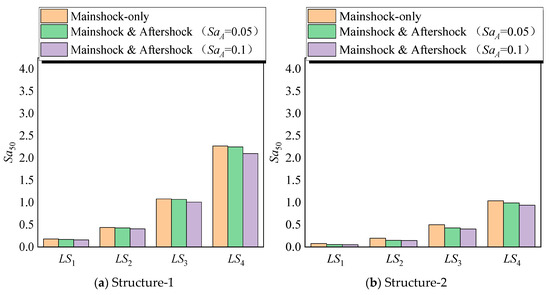
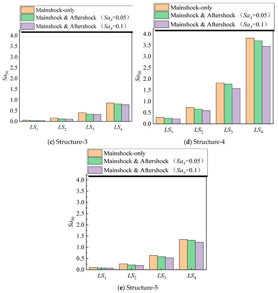
Figure 13.
The values of Sa50 for different structures.
For the intact structure (Structure-1), the Sa50 for LS4 in the mainshock-only scenario is 2.27 g. After adding an SaA = 0.05 g aftershock, this value reduces to 2.25 g and further reduces to 2.1 g for an SaA = 0.1 g aftershock. This reduction is relatively small (approximately 1–7%) but still noticeable. The structure’s capacity to withstand large deformations is reduced due to the cumulative cyclic loading of the mainshock and aftershock. This is consistent with findings in the literature that show aftershocks, even of moderate intensity, contribute to cumulative damage accumulation, particularly in structures already experiencing inelastic deformations [49].
In contrast, the influence of aftershocks is more significant in the corroded case structures. For example, the 10% corrosion structure (Structure-2) experiences a reduction in values of Sa50 from 1.04 g in the mainshock-only scenario to 0.99 g and 0.94 g under 0.05 g and 0.1 g aftershocks, respectively. This reduction of about 10% indicates the additional seismic demand introduced by aftershocks, which intensifies the deterioration of the already weakened reinforcing steel. The corrosion-induced reduction in cross-section and bond strength makes the structure more susceptible to early stiffness loss and premature failure when subjected to repeated seismic loading.
For FRP-strengthened structures, the reduction in performance due to aftershocks is less severe but still significant. For example, Structure-4 shows an Sa50 of 3.82 g at LS4 under the mainshock-only case, which reduces to 3.7 g under the 0.05 g aftershock and 3.45 g under the 0.1 g aftershock. Although the reduction is smaller compared with the corroded case structures without FRP, it still reflects the effect of additional cyclic loading that leads to further degradation of concrete stiffness and the bond between the FRP and the concrete substrate [50]. Despite the decline, these results show that FRP retrofitting remains highly effective in recovering or even exceeding the seismic performance of the intact structure, especially under moderate corrosion conditions.
5.2. Evaluation of the Impact of Aftershocks on Corrosion-Induced Degradation
The degradation of seismic performance due to corrosion is significantly aggravated by aftershocks. Corrosion typically leads to a loss of rebar cross-sectional area, bond deterioration, and a reduction in the overall stiffness of RC structures [51,52]. These effects are compounded under aftershock loading, which leads to further deterioration in structural behavior.
Structure-5 in the mainshock-only scenario has an Sa50 of LS4 of 1.35 g, which is 40% lower than the intact reference (2.27 g). This reduction is primarily due to the mechanical loss of reinforcement, which leads to decreased flexural and shear capacities and the associated bond degradation, which impairs the force transfer between the reinforcement and concrete [53]. Under aftershock loading, the Sa50 drops to 1.31 g for a 0.05 g aftershock and to 1.22 g for a 0.1 g aftershock. These further reductions reflect the cumulative effects of aftershocks on already weakened structures. As the structure suffers additional loading cycles, previously formed cracks tend to widen, reducing overall stiffness and increasing vulnerability.
The results indicate that aftershocks can significantly aggravate the bond–slip effects that already exist in corroded structures. As corrosion progresses, the corrosion products lead to internal forces, creating microcracks that severely degrade the bond between steel and concrete. The additional cyclic loading from aftershocks accelerates the propagation of these microcracks, leading to more rapid stiffness degradation and loss of load-carrying capacity.
5.3. Effectiveness of FRP Strengthening Under Combined Mainshock–Aftershock Loading
FRP retrofitting is effective in restoring the seismic performance of corroded RC structures, as it provides additional confinement, improves crack control, and delays structural failures [54]. However, aftershocks degrade the effectiveness of FRP, especially at higher levels of corrosion.
In Structure-4, the Sa50 for LS4 under the mainshock is 3.82 g, which is 65% higher than the intact structure. This increase can be attributed to the FRP’s contribution to both strength (by carrying part of the tensile force) and ductility (by improving confinement and delaying concrete spalling). However, aftershocks lead to a reduction in the effectiveness of FRP. For example, the value of Sa50 at LS4 decreases to 3.7 g under the 0.05 g aftershock and to 3.45 g under the 0.1 g aftershock. This decline highlights that aftershocks affect the FRP–concrete interface, reducing the overall composite action between the FRP and the concrete substrate.
The bond between FRP and concrete is particularly vulnerable to aftershock loading, as it can lead to microcracking at the FRP–concrete interface. This degradation reduces the ability of the FRP to fully develop its tensile strength, particularly at higher damage levels. Furthermore, the additional cycles of loading induced by aftershocks can accelerate the deterioration of the concrete core, leading to a gradual reduction in structural capacity.
5.4. Damage State-Specific Behavior Under Mainshock and Aftershock Loading
The influence of aftershocks on the behavior of corroded and FRP-strengthened structures is most significant at higher damage states. Initial cracking (LS1) and moderate damage (LS2, LS3) show limited changes under aftershock loading, but as the structure approaches collapse (LS4), the effects of aftershocks become more significant.
Corroded structures without FRP show a significant degradation in seismic performance at LS4. For example, Structure-3 exhibits an Sa50 of 1.04 g under the mainshock, which decreases to 0.94 g under the 0.1 g aftershock. This reduction is due to amplified bond–slip and reduced confinement effects. On the other hand, the FRP-strengthened structures show a more gradual decline in fragilities under aftershock loading. For Structure-4, the Sa50 at LS4 decreases from 3.82 g (mainshock-only) to 3.7 g (0.05 g aftershock) and 3.45 g (0.1 g aftershock). The reason for this is that the FRP jacket provides confinement and crack control, which delay large residual deformations and limit the accumulation of inelastic damage. However, the additional loading cycles from the aftershock reduce the ability of the FRP system to maintain full effectiveness, leading to a gradual decline in performance.
6. Conclusions
This study conducted a seismic fragility analysis to quantify the effects of reinforcement corrosion and FRP retrofitting on an RC frame structure, with a particular focus on the cumulative damage from mainshock–aftershock sequences. Based on the computed fragilities and the comparative analysis of different loading scenarios, several conclusions can be drawn as follows:
(1) The corrosion effect can significantly degrade the seismic performance of RC structures, even at moderate levels. The results show that the corrosion-induced reductions in the values of median fragilities (Sa corresponding to 50% probability of exceeding each damage state, Sa50) are nonlinear and progress with increasing corrosion levels. For example, for the un-strengthened 20% corrosion structure, the value of Sa50 at LS4 drops from 2.27 g (intact) to 1.35 g, reflecting a 40% reduction in collapse resistance capacity. The corrosion-induced degradation is exacerbated under aftershock loading, with the values of Sa50 further decreasing by up to 10–20% under the influence of 0.05 g and 0.1 g aftershocks.
(2) The aftershocks could significantly amplify the seismic fragilities of corroded structures. Even at moderate intensities (0.05 g and 0.1 g), the aftershocks contribute to cumulative damage accumulation, accelerating stiffness degradation, and promoting cracking in corroded and un-retrofitted structures. The results of fragilities clearly demonstrate that the seismic capacity of corroded structures, especially at higher damage states, is significantly reduced when aftershocks are considered. This effect is especially significant for structures with higher corrosion levels (20% corrosion), where aftershocks exacerbate the bond–slip and confinement effects, leading to earlier failure.
(3) The FRP retrofitting can restore or even exceed the seismic performance of intact structures, particularly for moderately corroded structures (≤10% corrosion). For instance, the FRP-retrofitted structure with 10% corrosion ratio shows a significant improvement in the values of Sa50 at all damage states, with Sa50 values at LS4 reaching 3.82 g, which is 65% higher than the intact reference. However, aftershocks reduce the effectiveness of FRP strengthening, though it still offers performance improvement over un-retrofitted structures. The FRP system continues to provide confinement and crack control, delaying failure, but the aftershock-induced degradation leads to a gradual reduction in seismic performance, particularly in the post-yield and collapse damage.
(4) The effect of corrosion and FRP strengthening on seismic fragility is potentially damage state-dependent. While the influence of corrosion is more prominent at higher damage states, FRP retrofitting provides significant structural resistance improvement, particularly at higher damage levels. For example, the FRP-retrofitted structure with 10% corrosion ratio exhibits a higher increase in seismic capacity compared to the intact structure at LS4, with a 68% improvement. In contrast, the 20% corrosion ratio structure without FRP shows a sharp decline in seismic capacity, with a 62% reduction at LS4. These findings highlight that FRP retrofitting becomes increasingly effective as the structure transitions from elastic to inelastic behavior, especially at higher damage states.
This study demonstrates that FRP retrofitting can effectively reverse corrosion-induced fragility degradation, restoring or even exceeding the seismic resilience of intact RC structures. Based on the findings of this study, it is recommended that the impact of aftershocks be carefully considered in the seismic design and retrofit strategies of RC structures, particularly those affected by corrosion. FRP retrofitting should be prioritized for structures with moderate corrosion (≤10%), as it can significantly improve both strength and ductility. Moreover, future design codes should incorporate the effects of aftershocks when assessing the seismic fragility of corroded and retrofitted structures to ensure a more comprehensive evaluation of structural resilience.
The reduced effectiveness of FRP under aftershock loading, partly attributed to interface degradation, points to the need for more sophisticated finite element models. In addition, to optimize retrofit decisions, future studies should integrate the developed fragility functions with lifecycle cost analysis and community resilience frameworks. This would allow for a quantitative comparison of the long-term benefits and cost-effectiveness of different retrofitting strategies against the risks posed by corrosion and sequential earthquakes.
Author Contributions
Conceptualization, K.-Y.D.; Methodology, Z.Z.; Software, D.-P.Y. and S.L.; Validation, D.-P.Y.; Formal Analysis, W.-Z.X.; Investigation, W.-Q.X. and Z.-B.G.; Resources, S.L.; Data Curation, Z.-B.G.; Writing—Original Draft, W.-Q.X. and K.-Y.D.; Writing—Review and Editing, W.-Z.X. and Z.Z.; Visualization, W.-Q.X., W.-Z.X. and S.L.; Funding Acquisition, K.-Y.D. and Z.Z. All authors have read and agreed to the published version of the manuscript.
Funding
This research was funded by the National Natural Science Foundation of China [grant number 52408502 and 52408564] and the Joint Fund for Science and Technology Research and Development Program of Henan Province [grant number 242301420027].
Data Availability Statement
The original contributions presented in this study are included in the article. Further inquiries can be directed to the corresponding author.
Acknowledgments
The opinions and findings presented are those of the writers and do not necessarily reflect the views of the sponsor.
Conflicts of Interest
Authors W.-Q.X., W.-Z.X., Z.-B.G., D.-P.Y. and S.L. are employed by The Fourth Construction Co., Ltd. of China State Construction Fifth Engineering Bureau. The remaining authors declare that they have no known competing financial interests or personal relationships that could have appeared to influence the work reported in this paper.
Notation Table
| Symbol | Definition |
| d | Effective depth of the column section |
| fy | Yield strength of longitudinal reinforcement |
| k | Ratio of capping moment to yield moment in the backbone curve |
| Ls | Shear span |
| My | Yield moment in the backbone curve |
| ρeff | Effective transverse reinforcement ratio |
| ρl | Longitudinal reinforcement ratio |
| s | Stirrup spacing |
| sn | Reinforcement buckling coefficient |
| sr | Shear force ratio |
| θy | Chord rotation at the elastic stage in the backbone curve |
| θp | Chord rotation at the strain-hardening stage in the backbone curve |
| θpc | Chord rotation at the post-capping stage in the backbone curve |
| γl | Corrosion rate of longitudinal reinforcement |
| γs | Corrosion rate of stirrup |
| λ | Cyclic deterioration parameter in the modified I–M–K model |
| v | Axial load ratio |
References
- Liel, A.B.; Deierlein, G.G. Using collapse risk assessments to inform seismic safety policy for older concrete buildings. Earthq. Spectra 2012, 28, 1495–1521. [Google Scholar] [CrossRef]
- Zhou, Z.; Han, M.; Dong, Y.; Yu, X. Seismic resilience of corroded mid-rise reinforced concrete structures under mainshock-aftershock sequences. Eng. Struct. 2023, 288, 116192. [Google Scholar] [CrossRef]
- Afsar Dizaj, E.; Salami, M.R.; Kashani, M.M. Seismic vulnerability assessment of ageing reinforced concrete structures under real mainshock-aftershock ground motions. Struct. Infrastruct. Eng. 2022, 18, 1674–1690. [Google Scholar] [CrossRef]
- Yu, X.H.; Dai, K.Y.; Li, Y.S. Variability in corrosion damage models and its effect on seismic collapse fragility of aging reinforced concrete frames. Constr. Build. Mater. 2021, 295, 123654. [Google Scholar] [CrossRef]
- Zhang, X.; Zhang, Y.; Liu, B.; Liu, B.; Wu, W.; Yang, C. Corrosion-induced spalling of concrete cover and its effects on shear strength of RC beams. Eng. Fail. Anal. 2021, 127, 105538. [Google Scholar] [CrossRef]
- Zhou, Z.; Dai, K.; Feng, D.; Yu, X. State-dependent life-cycle structural seismic resilience analysis incorporating corrosion and aftershock effects: Illustrated with a corroded RC frame. Bull. Earthq. Eng. 2025, 23, 4609–4634. [Google Scholar] [CrossRef]
- Hg, L.P.; Chen, J.J.; Kwana, A.; Guan, G.X. Improving sustainability and compressive strength of fiber reinforced concrete by adding granite powder waste as paste replacement. Sustain. Eng. Mater. 2025, 1, 000003. [Google Scholar] [CrossRef]
- Malumbela, G.; Alexander, M.; Moyo, P. Variation of steel loss and its effect on the ultimate flexural capacity of RC beams corroded and repaired under load. Constr. Build. Mater. 2010, 24, 1051–1059. [Google Scholar] [CrossRef]
- Shu, Q.; Wang, K.; Yuan, G.; Zhang, Y.; Lu, L.; Liu, Z. Assessing capacity of corroded angle members in steel structures based on experiment and simulation. Constr. Build. Mater. 2020, 244, 118210. [Google Scholar] [CrossRef]
- Zhou, Z.; Yu, X.; Gardoni, P.; Ji, K.; Lu, D. Seismic risk estimates for reinforced concrete structures with incorporation of corrosion and aftershock. Reliab. Eng. Syst. Saf. 2025, 254, 110585. [Google Scholar] [CrossRef]
- Zhou, Z.; Lu, D.; Gardoni, P.; Han, M.; Yu, X. Probabilistic risk assessment for reinforced concrete frame structures subject to mainshock-aftershock sequences. Earthq. Eng. Struct. Dyn. 2024, 53, 2405–2422. [Google Scholar] [CrossRef]
- Saed, G.; Balomenos, G.P. Fragility framework for corroded steel moment-resisting frame buildings subjected to mainshock-aftershock sequences. Soil Dyn. Earthq. Eng. 2023, 171, 107975. [Google Scholar] [CrossRef]
- Di Sarno, L.; Pugliese, F. Effects of mainshock-aftershock sequences on fragility analysis of RC buildings with ageing. Eng. Struct. 2021, 232, 111837. [Google Scholar] [CrossRef]
- Yang, J.; Haghani, R.; Blanksvärd, T.; Lundgren, K. Experimental study of FRP-strengthened concrete beams with corroded reinforcement. Constr. Build. Mater. 2021, 301, 124076. [Google Scholar] [CrossRef]
- Zhu, G.B.; Cheng, Y.L.; Wang, P.H.; Chai, F.S.; Chen, M.; Bai, W.D.; Yu, Z.Y.; Dai, K.Y.; Yu, X.H. Multi-objective collaborative optimization of mechanical and shrinkage properties for engineered geopolymer composites based on orthogonal experimental design. Case Stud. Constr. Mater. 2025, 23, e05556. [Google Scholar] [CrossRef]
- Dai, K.-Y.; Yang, A.; Song, G.-H.; Bi, K.; Yang, J.-W.; Zhou, Z.; Yu, B.; Yu, X.-H. Experimental study on seismic performance of non-ductile RC columns with corroded steel bars. Structures 2025, 77, 109034. [Google Scholar] [CrossRef]
- Gudonis, E.; Timinskas, E.; Gribniak, V.; Kaklauskas, G.; Arnautov, A.K.; Tamulėnas, V. FRP reinforcement for concrete structures: State-of-the-art review of application and design. Eng. Struct. Technol. 2013, 5, 147–158. [Google Scholar] [CrossRef]
- Liu, X.; Li, Y. Static bearing capacity of partially corrosion-damaged reinforced concrete structures strengthened with PET FRP composites. Constr. Build. Mater. 2019, 211, 33–43. [Google Scholar] [CrossRef]
- Valente, M. Seismic upgrading strategies for non-ductile plan-wise irregular R/C structures. Procedia Eng. 2013, 54, 539–553. [Google Scholar] [CrossRef]
- Valente, M.; Milani, G. Alternative retrofitting strategies to prevent the failure of an under-designed reinforced concrete frame. Eng. Fail. Anal. 2018, 89, 271–285. [Google Scholar] [CrossRef]
- Xu, S.; Li, W.; Wang, X.; Zhang, H.; Liu, J.; Jiang, H.; Wang, X.; Ma, H.; Shi, J.; Yu, Z.; et al. The Mechanical Properties and Durability of the PE-BFRP Hybrid-Fiber-Engineered Cementitious Composite (ECC). Buildings 2025, 15, 1860. [Google Scholar] [CrossRef]
- Masoud, S.; Soudki, K.; Topper, T. Postrepair fatigue performance of FRP-repaired corroded RC beams: Experimental and analytical investigation. J. Compos. Constr. 2005, 9, 441–449. [Google Scholar] [CrossRef]
- Zheng, A.; Li, S.; Zhang, D.; Yan, Y. Shear strengthening of RC beams with corrosion-damaged stirrups using FRP grid-reinforced ECC matrix composites. Compos. Struct. 2021, 272, 114229. [Google Scholar] [CrossRef]
- Xu, J.G.; Wu, G.; Feng, D.C.; Cotsovos, D.M.; Lu, Y. Seismic fragility analysis of shear-critical concrete columns considering corrosion induced deterioration effects. Soil Dyn. Earthq. Eng. 2020, 134, 106165. [Google Scholar] [CrossRef]
- Choe, D.E.; Gardoni, P.; Rosowsky, D.; Haukaas, T. Seismic fragility estimates for reinforced concrete bridges subject to corrosion. Struct. Saf. 2009, 31, 275–283. [Google Scholar] [CrossRef]
- Yang, J.; Guo, T.; Luo, D.; Liu, Z. Multiscale modeling and seismic fragility analysis of corroded precast concrete frame. J. Perform. Constr. Facil. 2021, 35, 04020128. [Google Scholar] [CrossRef]
- Liu, Y.; Hao, Y.; Hao, H.; Zhou, Y. Fragility assessment of FRP-strengthened RC beams with chloride-induced corrosion damage under impact loads. Reliab. Eng. Syst. Saf. 2025, 266, 111728. [Google Scholar] [CrossRef]
- Zhang, J.; Qin, Q.; Wang, L.; Yi, J.; An, B.; Zhou, J. Corrosion resistance and deterioration mechanism of coral concrete reinforced with steel-FRP composite bars. J. Build. Eng. 2025, 107, 112764. [Google Scholar] [CrossRef]
- Tabandeh, A.; Gardoni, P. Probabilistic capacity models and fragility estimates for RC columns retrofitted with FRP composites. Eng. Struct. 2014, 74, 13–22. [Google Scholar] [CrossRef]
- Jia, D.; Mao, J.; Guo, Q.; Yang, Z.; Xiang, N. A flexure-capacity design method and seismic fragility assessment of FRP/steel double-reinforced bridge piers. Struct. Infrastruct. Eng. 2020, 16, 1311–1325. [Google Scholar] [CrossRef]
- Zheng, A.; Zong, S.; Lu, Y.; Li, S. Fatigue performance of corrosion-damaged beams strengthened with FRP grid-reinforced ECC matrix composites. Eng. Struct. 2022, 255, 113938. [Google Scholar] [CrossRef]
- Ghosh, J.; Padgett, J.E. Aging considerations in the development of time-dependent seismic fragility curves. J. Struct. Eng. 2010, 136, 1497–1511. [Google Scholar] [CrossRef]
- GB50010–2010; Code for Seismic Design of Concrete Structures, National Standard of the People’s Republic of China. China Architecture & Building Press: Beijing, China, 2015.
- Wang, Y.; Wang, P.; Wan, D.B.; Zhang, B.; Li, Y.H.; Huo, H.; Yu, Z.Y.; Qu, Y.W.; Dai, K.Y. Determining the Optimal FRP Mesh–ECC Retrofit Scheme for Corroded RC Structures: A Novel Multi-Dimensional Assessment Framework. Buildings 2025, 15, 3823. [Google Scholar] [CrossRef]
- National Standards. Technical Standard for Fiber Reinforced Polymer (FRP) in Construction; China Planning Press: Beijing, China, 2020. [Google Scholar]
- Li, L.; Chen, J.; Wang, W.; Dai, K.; Hu, W. Experimental and prediction model of axial compressive responses of corroded RC cylinders strengthened with CFRP. Eng. Struct. 2024, 317, 118649. [Google Scholar] [CrossRef]
- Ibarra, L.F.; Medina, R.A.; Krawinkler, H. Hysteretic models that incorporate strength and stiffness deterioration. Earthq. Eng. Struct. Dyn. 2005, 34, 1489–1511. [Google Scholar] [CrossRef]
- Dai, K.Y.; Yu, X.H.; Wang, S.; Lü, D.G. Identification of the hysteretic model parameters for reinforced concrete circular columns based on the modified Ibarra-Medina-Krawinkler material model. Eng. Mech. 2021, 38, 154–163. [Google Scholar]
- Haselton, C.B.; Liel, A.B.; Taylor-Lange, S.C.; Deierlein, G.G. Calibration of model to simulate response of reinforced concrete beam-columns to collapse. ACI Struct. J. 2016, 113, 1141–1152. [Google Scholar] [CrossRef]
- Dai, K.; Yu, X.; Jiang, Z.; Wang, D.; Qian, K. Hysteretic model for corroded reinforced concrete columns retrofitted with FRP. Constr. Build. Mater. 2023, 380, 131207. [Google Scholar] [CrossRef]
- Zheng, S.S.; Dong, L.G.; Zuo, H.S.; Qin, Q.; Liu, W.; Li, Q.Q. Experimental investigation on seismic behaviors of corroded RC frame columns in artificial climate. J. Build. Struct. 2018, 39, 28–36. [Google Scholar]
- Xia, Y. Experimental Study Under Cyclic Loading on Durably Damaged Reinforced Concrete Column Joint. Master’s Thesis, Central South University, Changsha, China, 2014. [Google Scholar]
- Lao, T.A. Experimental Study on Seismic Performance of Corroded Reinforced Concrete Columns Under High Strain FRP Constraints. Master’s Thesis, Shenzhen University, Shenzhen, China, 2018. [Google Scholar]
- Karimipour, A.; Edalati, M. Retrofitting of the corroded reinforced concrete columns with CFRP and GFRP fabrics under different corrosion levels. Eng. Struct. 2021, 228, 111523. [Google Scholar] [CrossRef]
- Chiou, B.; Darragh, R.; Gregor, N.; Silva, W. NGA project strong-motion database. Earthq. Spectra 2008, 24, 23–44. [Google Scholar] [CrossRef]
- Wang, M. Research on Generation of Aftershock Ground Motion Based on Machine Learning Method. Master’s Thesis, Harbin Institute of Technology, Harbin, China, 2022. [Google Scholar]
- Singhal, A.; Kiremidjian, A.S. Method for probabilistic evaluation of seismic structural damage. J. Struct. Eng. 1996, 122, 1459–1467. [Google Scholar] [CrossRef]
- Zhou, Z.; Xu, H.; Gardoni, P.; Lu, D.; Yu, X. Probabilistic demand models and fragilities for reinforced concrete frame structures subject to mainshock-aftershock sequences. Eng. Struct. 2021, 245, 112904. [Google Scholar] [CrossRef]
- Jalayer, F.; Ebrahimian, H. Seismic risk assessment considering cumulative damage due to aftershocks. Earthq. Eng. Struct. Dyn. 2017, 46, 369–389. [Google Scholar] [CrossRef]
- Pham, T.M.; Hao, H. Review of concrete structures strengthened with FRP against impact loading. Structures 2016, 7, 59–70. [Google Scholar] [CrossRef]
- Berto, L.; Simioni, P.; Saetta, A. Numerical modelling of bond behaviour in RC structures affected by reinforcement corrosion. Eng. Struct. 2008, 30, 1375–1385. [Google Scholar] [CrossRef]
- Biswas, R.K.; Iwanami, M.; Chijiwa, N.; Uno, K. Effect of non-uniform rebar corrosion on structural performance of RC structures: A numerical and experimental investigation. Constr. Build. Mater. 2020, 230, 116908. [Google Scholar] [CrossRef]
- Marí, A.; Bairán, J.; Cladera, A.; Oller, E.; Ribas, C. Shear-flexural strength mechanical model for the design and assessment of reinforced concrete beams. Struct. Infrastruct. Eng. 2015, 11, 1399–1419. [Google Scholar] [CrossRef]
- Stewart, M.G. Mechanical behaviour of pitting corrosion of flexural and shear reinforcement and its effect on structural reliability of corroding RC beams. Struct. Saf. 2009, 31, 19–30. [Google Scholar] [CrossRef]


Disclaimer/Publisher’s Note: The statements, opinions and data contained in all publications are solely those of the individual author(s) and contributor(s) and not of MDPI and/or the editor(s). MDPI and/or the editor(s) disclaim responsibility for any injury to people or property resulting from any ideas, methods, instructions or products referred to in the content. |
© 2025 by the authors. Licensee MDPI, Basel, Switzerland. This article is an open access article distributed under the terms and conditions of the Creative Commons Attribution (CC BY) license (https://creativecommons.org/licenses/by/4.0/).