Abstract
Aluminum alloys offer advantages such as lightweight properties, high strength, and excellent corrosion resistance. To expand their application in long-span spatial structures, prestressed cables have been introduced into aluminum alloy structural systems, forming a new type of string-beam structure. To further investigate the static performance of aluminum alloy string-beam structures, a static analysis was conducted based on the greenhouse project for the archaeological site of the Qin Eastern Mausoleum. This analysis examined the structural response under various load combinations, as well as the effects of the number of struts, cross-sectional area of the cables, prestress level in the cables, and the sag-to-span ratio of the cables. The results indicate that the incorporation of prestressed cables significantly enhances the static performance of aluminum alloy string-beam structures. Under the most critical load combination, the maximum stress observed was 189.45 MPa, and the maximum vertical displacement was 137.31 mm, both of which comply with design specifications. The structure was found to be most sensitive to temperature load. From the perspectives of structural performance and construction economy, setting the number of struts between five and seven is optimal. Increasing the cross-sectional area of the cables effectively reduces structural deflection but leads to an increase in internal stress. Similarly, increasing the prestress level effectively reduces structural displacement. The sag-to-span ratio of the cables has the most pronounced effect on structural stiffness: when the ratio increases from 0.025 to 0.065, the mid-span displacement increases by 33.51%. These findings demonstrate that aluminum alloy beam-string structures are suitable for long-span spatial structures.
1. Introduction
Aluminum alloys are recognized for their advantageous properties, such as low density, strong corrosion resistance, and favorable extrudability. These characteristics make aluminum alloys particularly suitable for long-span spatial structures, where reducing self-weight while maintaining structural capacity is crucial. Since the 1950s, these materials have shown outstanding performance in spatial structures and have been extensively employed in the construction of large-span venues, including stadiums, natatoriums, memorial halls, and science museums [1,2,3]. Although the development of aluminum alloy structures started relatively late in China, it has advanced at a notable pace, with several large-scale aluminum alloy spatial grid structures already built [4]. A comprehensive experimental investigation and analysis of the local buckling behaviour and structural behavior of 7A04-T6 high-strength aluminium alloy H-section stub columns and double shear connections in fire were conducted by Wang et al. [5,6,7,8]. Wang et al. [9] proposed a method to enhance the connection design method for single-layer aluminum alloy grid shells on the basis of generative design (GD) and topology optimization. A novel hybrid pultruded fiber reinforced polymer (FRP)-aluminum space truss system was proposed by Zhu et al. [10], aiming to be used as a pedestrian bridge or platform in marine areas. A series of four-point bending tests investigating global buckling of cold-rolled aluminium alloy channel beam members was presented, and a total of twenty specimens of three commercially available channel sections with two thicknesses and various lengths were tested by Pham et al. [11,12]. A total of seven 7075-T6 high-strength aluminium alloy extruded H-section beams were tested under concentrated loads, including four specimens with mid-span stiffeners and three without mid-span stiffeners by Lu et al. [13].
Tan et al. [14] demonstrated that for single-layer aluminum alloy shells spanning over 100 m, both economic efficiency and static performance surpass those of equivalent steel structures. Their study also examined the influence of key design parameters-such as boundary conditions, cross-sections of truss beams, chord member dimensions, and sag-to-span ratios on structural behavior. Sun et al. [15,16] carried out static loading tests on a K6-type spherical shell model to investigate the static stability of single-layer aluminum alloy reticulated shells, analyzing deformation patterns, internal force distribution, and failure mechanisms. With the growing demand for long-span building systems, the application of prestressing technology in aluminum alloy structures has garnered increasing research interest. Gou et al. [17] focused on the design of a single-layer aluminium alloy reticulated shell with a 2 m span, which was subjected to an impact test to examine its dynamic response and failure mode. The structural response and failure mechanisms under such extreme conditions of aluminium alloy thin-walled cylindrical shells subjected to instantaneous axial loads were studied by Zhang et al. [18]. A numerical model of the members considering the roof-connection construction is proposed, and the influence of the presence or absence of constructions on the failure modes and buckling strength is investigated by Ying et al. [19]. Xiong et al. [20] proposed a parametric analysis scheme to investigate the influence of the sag-to-span ratios, length-to-span ratios, span-to-thickness ratios, loading conditions, and initial geometric imperfections on the elasto-plastic buckling behaviour of aluminium alloy cylindrical reticulated shells with gusset joints. Mascolo et al. [21] developed a physics-guided optimization framework for adjusting cable forces using reduced-order influence operators and multi-objective metaheuristics.
Based on the Qin Eastern Mausoleum archaeological work shelter project, this study conducts a comprehensive static performance analysis of a tensioned aluminum alloy beam structural system. The investigation assesses the influence of wind, snow, and temperature loads on the structural behavior, and further examines how key parameters-such as the number of struts, cable cross-sectional area, cable prestress level, and cable sag-to-span ratio-affect the overall stiffness and static response. The findings provide a scientific basis and reference for the optimization of such structural systems.
2. Project Overview
The Qin Eastern Mausoleum archaeological shelter project is located in Xi’an, Shaanxi Province, covering a total floor area of 16,020 m2 and designed with a seismic fortification intensity of 8 degrees. The project rendering is shown in Figure 1. This paper focuses on the central shelter, which adopts a tensioned aluminum alloy beam structure (TABS) comprising aluminum alloy arch beams and prestressed cables. With a height of 20 m, a span of 70 m, and column spacing of 5.5 m, it currently represents the largest-span tensioned aluminum alloy structure in China. The structural system consists of steel–concrete composite columns, aluminum alloy arch beams, tension cables, and struts.
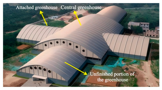
Figure 1.
Archaeological work shed effect drawing.
The construction site is illustrated in Figure 2. The aluminum alloy arch beams adopt a double-web H-shaped cross-section. To prevent electrochemical corrosion between dissimilar metals, the concrete-filled steel tube columns are connected to the aluminum alloy arch beams via stainless steel connectors and ring-groove rivets. The stay cables consist of hot-extruded polyethylene (PE)-sheathed steel strands. The struts are made of Q355B round steel bars, with their lower ends anchored to the concrete-filled steel tube columns. A schematic of the single-bay structure is presented in Figure 3, and the corresponding detailed parameters are summarized in Table 1, including the yield Strength, ultimate Strength, modulus of elasticity, Poisson’s ratio, density, and thermal expansion coefficient.
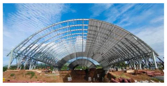
Figure 2.
Construction site.
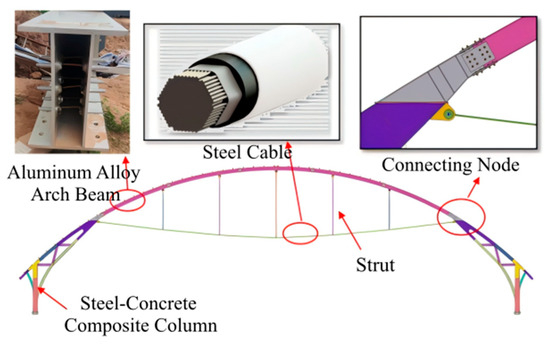
Figure 3.
Single unit structure.

Table 1.
Details of the main components of the aluminum alloy string beam structure.
3. Static Performance Analysis
3.1. Establish a Finite Element Model
A finite element model was established using MIDAS Gen version 2023 to simulate the structural behavior. As shown in Figure 4, the model discretized the aluminum alloy arch girders using beam elements, the struts with truss elements, the cables with tension-only elements, and the steel-concrete composite columns with solid elements.
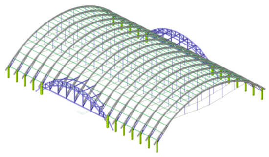
Figure 4.
Finite element analytical model.
Cables are modeled as tension-only truss elements with a large displacement formulation enabled. The nonlinear cable stiffness due to sag effect was considered using the Ernst modulus correction for inclined cables under tension, though the primary nonlinearity was handled through the geometric update in the analysis. Arch beams and struts are modeled using beam elements with P-Delta and large displacement effects included. Analysis type: A geometrically nonlinear static analysis was performed using the updated Lagrangian formulation in MIDAS Gen 2024v2.1. The equilibrium iterations accounted for changes in structural geometry under load.
The analysis used constant elastic modulus (E) at room temperature, as the temperature variations considered are within the range where E degradation for aluminum and steel is negligible for static serviceability analysis.
The steel–concrete composite columns were modeled as fixed supports. The connection between the aluminum arch and steel column was modeled as a rigid connection using a stiff stainless steel connector, which restrains transitional degrees of freedom but allows differential thermal strain to develop internal forces.
The results of the MIDAS model of a simplified single-span tensioned beam with published experimental data from Tan et al. [14]. It showed a good agreement.
3.2. Design Parameters and Load Combinations
3.2.1. Design Parameters
The structure was designed for a 50-year service life, with a seismic fortification category of Grade C and a safety level of Class II. The considered loads include dead load (D), live load (L), wind load (W), snow load (S), and temperature load (T). The dead load comprises the self-weight of the structure and the superimposed load from the roof and purlins, with a characteristic value of 1.3 kN/m2. The live load is taken as 0.5 kN/m2. The wind load, determined based on a 50-year return period and terrain category B, is 0.35 kN/m2. The snow load is 0.25 kN/m2, while the thermal load considers temperature variations of +50 °C and –25 °C.
Geometric nonlinearity was enabled using the updated Lagrangian formulation in MIDAS Gen. Large displacement effects and cable sag were considered. Material nonlinearity was not included.
3.2.2. Load Combinations
The structure was designed to account for ten primary load types, including dead load (D), live load (L), wind loads in both positive and negative X- and Y-directions (Wx+, Wx−, Wγ+, Wγ−), asymmetric snow loads on the left and right half-spans (SL, Sr), and positive/negative temperature actions (T+, T−). Prestress was applied as an initial tensile force in the cable elements due to the temperature change.
In accordance with the Code for Design of Building Structures (GB 50009), both the ultimate limit state and the serviceability limit state were considered in the structural design. A total of twenty representative load combinations were selected from the MIDAS analysis results for detailed evaluation, as summarized in Table 2.
Table 2.
Representative load combination.
3.3. Static Calculation Results
The maximum displacement and stress values of the structure under various load combinations are compiled in Table 3.
Table 3.
The calculation results of each load condition.
As summarized in Table 3, the maximum structural stress is 189.45 MPa, which remains below the yield strength of the aluminum alloy material, thereby satisfying the strength safety requirements. The average stress ratio is approximately 0.5, reflecting both a considerable safety margin and efficient use of material. The maximum vertical displacement is 137.31 mm, within the allowable deflection limit of span/250 as prescribed by the design code.
3.3.1. Influence of Snow Load Distribution on Structural Static Performance
In long-span cable-supported structures, particular attention must be given to the potential uneven distribution of snow loads across half-spans. The specific snow load distribution pattern applied in this study is illustrated in Figure 5, with the corresponding load combinations derived from load case SC6.

Figure 5.
Distribution form of live load over half-span. (a) Full-span arrangement (SC6-I); (b) Lower crossbar arrangement (SC6-II); (c) Left-side layout (SC6-III); (d) Right half-span arrangement (SC6-IV).
The structural response under the four aforementioned load combinations was evaluated. The corresponding displacement and stress distributions are illustrated in Figure 6, Figure 7, Figure 8 and Figure 9. The locations of maximum stress are shown in the figures.
Figure 6.
Results of SC6-I. (a) Displacement; (b) stress.
Figure 7.
Results of SC6-II. (a) Displacement; (b) stress.
Figure 8.
Results of SC6-III. (a) Displacement; (b) stress.
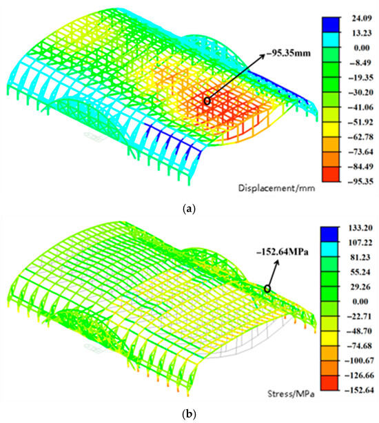
Figure 9.
Results of SC6-IV. (a) Displacement; (b) stress.
- (1)
- Under the SC6-II load condition, the maximum vertical displacement of the structure is 108.72 mm. Compared with the SC6-I condition, the maximum displacement decreases by 3.54 mm under SC6-III and by 1.54 mm under SC6-IV. The relatively small variation in maximum vertical displacement across loading scenarios indicates that the snow load distribution pattern has only a limited influence on overall structural deformation.
- (2)
- The maximum structural stress occurs under the SC6-I condition, corresponding to full-span snow load, with a peak value of 152.85 MPa. Under SC6-IV, the maximum stress is 152.64 MPa-differing by only 0.21 MPa from the full-span case. Moreover, the stress distribution trends in the rear half-span are nearly identical under both load combinations, and the locations of maximum compressive stress closely align. In contrast, the maximum stress under SC6-III decreases by 15.66% compared to SC6-IV. This reduction is mainly due to structural asymmetry near the transition truss section, where variations in load distribution exert a more pronounced effect on stress response. Therefore, targeted reinforcement of structurally vulnerable regions should be considered during design to improve overall reliability.
3.3.2. Effect of Temperature Loads on Structural Static Performance
Since the coefficient of linear thermal expansion of 6061-T6 aluminum alloy is nearly twice that of ordinary steel, temperature loads have a significantly greater influence on structural deformation behavior [18]. To evaluate this effect, structural deformations under load cases LC4 and LC5 were analyzed, using the 1.3D load case as a reference. The comparative results are shown in Figure 10.
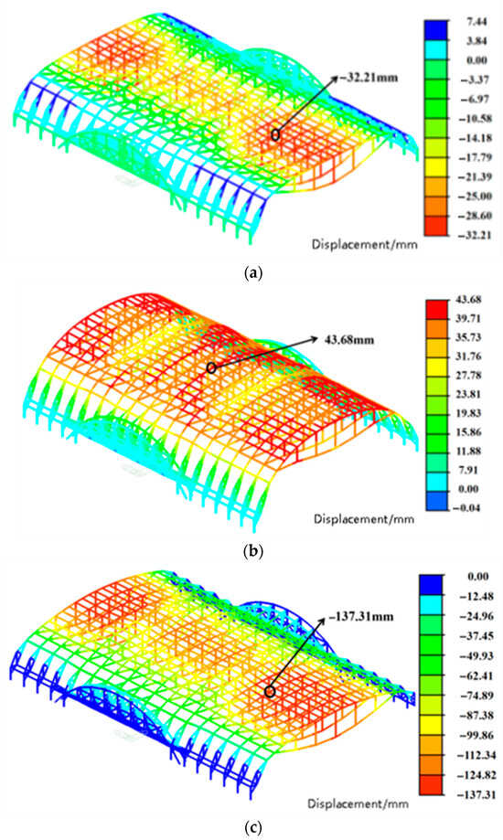
Figure 10.
Vertical displacement of the structure under temperature load. (a) 1.3D; (b) LC4; (c) LC5.
As shown in Figure 10:
- (1)
- Under constant load, the maximum vertical displacement of the structure is 32.21 mm, primarily occurring in regions not connected to the transfer truss. Under the LC4 load condition, the aluminum alloy arch beam deforms upward, with a maximum displacement of 43.68 mm, reversing its initial downward deflection. This behavior results from the significantly higher coefficient of thermal expansion of aluminum alloy compared to steel, causing substantial thermal expansion under elevated temperatures. The deformation at the base of the arch beam is constrained by the steel–concrete composite columns, inducing upward arching. Consequently, both the struts and prestressed cables deflect upward due to their mechanical interaction with the expanding arch beam. Under LC5 loading, the entire structure deforms downward, with a maximum displacement of 137.31 mm—within the allowable limits specified by the design code.
- (2)
- The structural system exhibits notable sensitivity to low-temperature effects. It is therefore essential to carefully evaluate displacement behavior under extreme temperature conditions during the design phase and to implement local reinforcement in vulnerable regions. Furthermore, the application of this structural system in extremely cold climates should be appropriately restricted.
3.3.3. Effect of Wind Loads on Structural Static Performance
In contrast to traditional long-span steel structures, tensioned aluminum alloy systems are characterized by lower stiffness, lighter self-weight, and smaller natural frequencies and damping ratios, making them more susceptible to wind-induced effects. This study examines the structural displacement and stress responses under SC2 and SC3 wind load conditions, with comparisons made against the SC1 baseline. The analysis results are presented in Figure 11, Figure 12 and Figure 13.
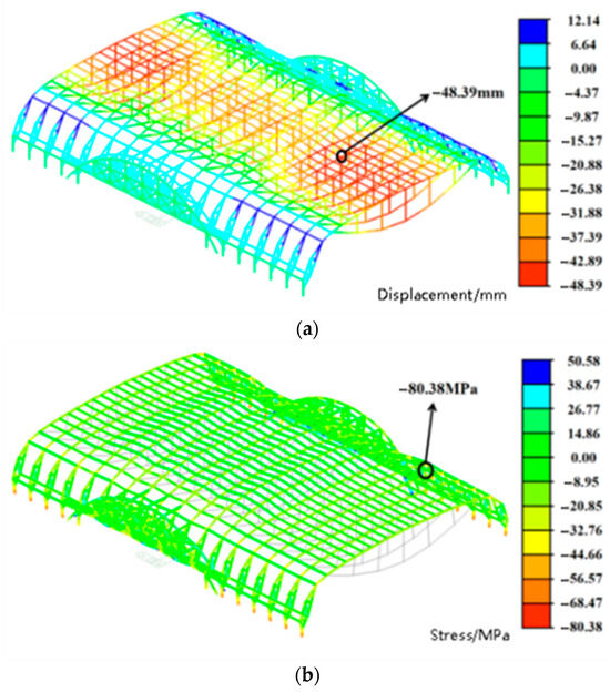
Figure 11.
Structural response nephogram under SC1 condition. (a) Vertical displacement; (b) stress.
Figure 12.
Structural response nephogram under SC2 condition. (a) Vertical displacement; (b) stress; (c) cable tension.

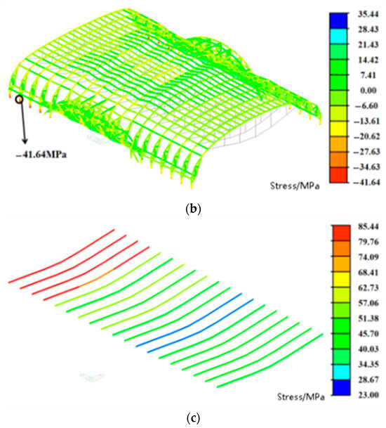
Figure 13.
Structural response nephogram under SC3 condition. (a) Vertical displacement; (b) stress; (c) cable tension.
- (1)
- Under SC2 loading, the maximum vertical displacement of the structure is 23.57 mm, representing a 51.29% reduction compared to the SC1 condition. The maximum stress is 40.27 MPa, corresponding to a 49.90% decrease relative to SC1. Both values remain well below the design strength of the aluminum alloy, indicating sufficient safety margins.
- (2)
- Under SC3 loading, the maximum vertical displacement is 30.70 mm, a 43.80% reduction compared to SC1. The displacement distribution pattern is consistent with that under SC2, with the maximum displacement occurring at approximately the same nodal location. Under both wind load cases, structural vertical displacement and stress are reduced to varying degrees, indicating that wind-induced upward suction partially counteracts the downward deformation caused by gravity loads.
- (3)
- Throughout the wind loading process, the cables remain in tension without slackening or failure, confirming the overall structural safety. In the design of similar structures, the uplifting effects of wind loads should be carefully considered to prevent potential instability resulting from cable relaxation or prestress loss.
4. Design Parameter Optimization Analysis
To optimize the geometric configuration of TABS, a comparative study of key design parameters is essential. Xiong et al. [20] highlighted the significant influence of both the vertical span ratio and cable prestress on the static performance of tensioned beam systems, though the underlying mechanisms require further investigation. In this study, the structural behavior under LC1 and SC1 loading conditions is examined by varying the number of struts, cable cross-sectional area, cable prestress, and cable vertical span ratio.
To ensure analytical consistency, a single-span tensioned aluminum alloy beam was used as the reference model. The baseline configuration includes five struts, a cable cross-sectional area of 531 mm2, a cable prestress of 180 kN, and a vertical span ratio of 0.045. All comparative models are derived from this reference, with only one parameter modified in each case.
4.1. Number of Struts
Structural analysis models were established with 1, 3, 5, 7, and 15 struts, respectively. The influence of the number of struts on mid-span displacement, cable internal forces, maximum strut axial force, and maximum stress in the aluminum alloy beams was systematically evaluated. The corresponding results are presented in Figure 14.
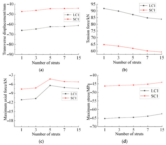
Figure 14.
Influence of the number of struts on the static performance. (a) Transverse displacement; (b) Cable tension; (c) Maximum axial force of the strut; (d) Maximum stress of beams.
As shown in Figure 14:
- (1)
- The vertical displacement at mid-span decreases as the number of struts increases. Beyond five struts, however, the rate of displacement reduction diminishes significantly. When the number of struts increases from one to five, the displacement decreases by less than 6%. With fifteen struts, the mid-span vertical displacement under load case LC1 is 61.21 mm—only 1.2 mm less than that of the reference model.
- (2)
- The cable internal force decreases with an increasing number of struts. When the number of struts rises from one to five, the reduction in cable force is less than 4%. Further increasing the number of struts beyond five has a negligible effect on the cable internal force. The maximum axial force in the struts initially decreases and then increases, reaching a minimum at five struts. When fifteen struts are used, the maximum axial force under LC1 reaches 7.38 kN, a 15.31% increase compared to the reference model.
- (3)
- The maximum stress in the aluminum alloy beam increases slightly with the number of struts, though the trend is not pronounced. As the number of struts increases from one to fifteen, the maximum beam stress under LC1 rises by only 3.92%.
- (4)
- Overall, the number of struts has a limited influence on mid-span displacement, cable internal force, and maximum beam stress, but a more noticeable effect on the maximum axial force in the struts. Excessively increasing the number of struts complicates construction and raises material costs, while too few struts may compromise structural safety. Therefore, a configuration of five to seven struts is recommended to balance structural performance and constructability.
4.2. Cross-Sectional Area of the Cable
The influence of cable cross-sectional area on the static performance of tensioned beam structures has received limited attention in previous studies. To systematically evaluate this parameter, five analysis models were established with cable cross-sectional areas of 380 mm2, 452 mm2, 531 mm2, 616 mm2, and 707 mm2. The corresponding results are presented in Figure 15.
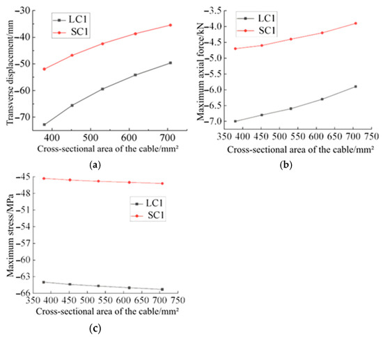
Figure 15.
Influence of the cross-sectional area of cables. (a) Transverse displacement; (b) Maximum axial force of the strut; (c) Maximum stress in aluminum alloy beams.
As shown in Figure 15, with the increase in cable cross-sectional area, the mid-span displacement and the maximum axial force in the struts decrease progressively, while the maximum stress in the aluminum alloy beam shows only a minor increase. As the cross-sectional area increases from 380 mm2 to 707 mm2, the mid-span displacement decreases by approximately 10% with each step. Under SC1 loading, the maximum axial force in the struts is reduced by 21.17%. These results indicate that increasing the cable cross-sectional area effectively enhances structural stiffness, mitigates vertical deformation, and alleviates axial force demand on the struts. However, an excessively large cross-sectional area may lead to increased self-weight, potentially offsetting these benefits.
4.3. Cable Prestressing
To examine the influence of cable prestress, analytical models were established with prestress levels of 0.6, 0.8, 1.0, 1.2, and 1.4 times the reference value (180 kN). The corresponding analysis results are presented in Figure 16.
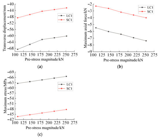
Figure 16.
Influence of the cables prestress on the structural static performance. (a) Transverse displacement; (b) maximum axial force of the strut; (c) maximum stress in aluminum alloy beams.
As shown in Figure 16:
- (1)
- With increasing cable prestress, the mid-span displacement of the structure decreases progressively. Under the SC1 loading condition, as the prestress increases from 108 kN to 180 kN, the mid-span displacement decreases by 9.08%. A further increase in prestress from 180 kN to 252 kN results in a mid-span displacement reduction of only 3.89% under the SC1 loading condition, indicating a diminishing effect of prestress augmentation on controlling structural deformation.
- (2)
- The maximum axial force in the struts increases significantly with higher cable prestress. When the prestress reaches 1.4 times the reference value, the maximum axial force under LC1 loading increases by 15.37% compared to the baseline model.
- (3)
- The maximum stress in the aluminum alloy beam increases approximately linearly with the prestressing force. As the prestress rises from 0.6 to 1.4 times the baseline value, the maximum beam stress under LC1 loading increases by only 4.09 MPa, suggesting that the influence of prestress on beam stress remains limited.
4.4. Cable Sag-to-Span Ratio
To further examine the influence of the cable sag-to-span ratio on the static performance of the TABS, analytical models were established with sag-to-span ratios of 0.025, 0.035, 0.045, 0.055, and 0.065. The corresponding analysis results are presented in Figure 17.
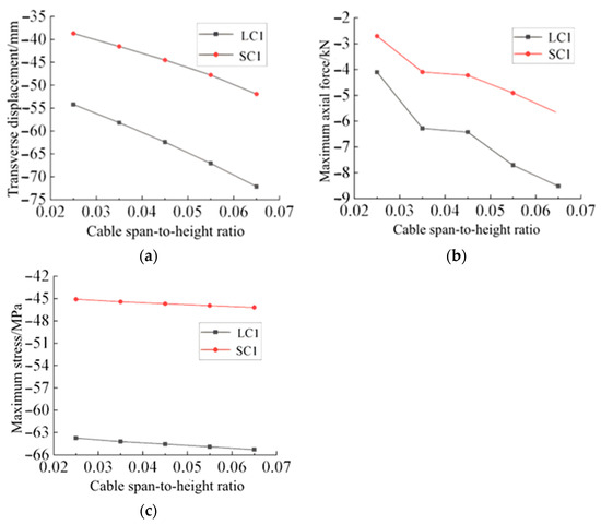
Figure 17.
Influence of the sag-to-span ratio of cables on the static performance. (a) Transverse displacement; (b) Maximum axial force of the strut; (c) Maximum stress in aluminum alloy beams.
As shown in Figure 17:
- (1)
- Under both LC1 and SC1 loading conditions, the mid-span displacement increases approximately linearly with the cable sag-to-span ratio. When the ratio rises from 0.025 to 0.065, the mid-span displacement increases by 33.51%.
- (2)
- As the cable sag-to-span ratio increases from 0.025 to 0.035, the maximum axial force in the struts under LC1 loading rises markedly by 47.84%, underscoring the significant influence of this parameter on structural behavior. Beyond a ratio of 0.035, the effect on strut axial force becomes less pronounced. Although the maximum stress in the aluminum alloy beam also increases with the sag-to-span ratio, the overall variation remains relatively small.
- (3)
- Variations in the cable sag-to-span ratio have a limited influence on the maximum stress in the aluminum alloy beam, with increases kept below 3% across the range studied. In structural design, however, the sag-to-span ratio substantially affects global displacement and strut axial force. It is therefore essential to comprehensively evaluate its impact on all key components to achieve an optimal balance among stiffness, stability, and material efficiency.
4.5. Design Recommendations
Quantified optimal ranges were proposed based on a multi-criteria evaluation. Balancing the stiffness, constructability, and strut force, the strut number should be 5–7. The cable sag-to-span ratio should be between 0.035 and 0.045 to minimize displacement and strut force. The cable area would be great for the structure with 500–600 mm2. Considering the effective displacement control without over-stressing struts, the prestress level should be 1.0–1.2 times the reference value.
5. Conclusions
- (1)
- The TABS exhibits favorable static performance under all load combinations. The maximum stress and vertical displacement are 189.45 MPa and 137.31 mm, respectively, both complying with design code requirements.
- (2)
- The structure is particularly sensitive to deformation under low-temperature conditions. Design of similar systems should carefully account for temperature-induced effects and incorporate local reinforcement in critical regions prone to stress concentration.
- (3)
- Based on a combined assessment of stiffness, force distribution, and constructability, the following parameter ranges are recommended for optimal design: 5–7 struts, cable sag-to-span ratio of 0.035–0.045, cable cross-sectional area of 500–600 mm2, and prestress level of 1.0–1.2 times the reference value.
Author Contributions
Conceptualization, C.H.; methodology, N.W. and K.X.; investigation, K.X. and J.L.; data curation, W.M.; writing—original draft preparation, N.W. and K.X.; writing—review and Editing, C.H. All authors have read and agreed to the published version of the manuscript.
Funding
Financial support for this work was provided by the Henan Province Key Research and Development Program (241111322000, 251111231500) and Program for Science and Technology Innovation Talents in Universities of Henan Province (26HASTIT068).
Data Availability Statement
The original contributions presented in this study are included in the article. Further inquiries can be directed to the corresponding author.
Conflicts of Interest
The authors declare no conflicts of interest.
References
- Zeng, J.; Lv, H.; Zhu, Z.; Dong, S.; Liu, Y.; Feng, X.; Li, W.; Shao, L. Seismic performance of pentagonal type aluminum alloy suspen-dome structure with large opening. Structures 2024, 69, 107312. [Google Scholar] [CrossRef]
- You, X.; Xing, Z.; Jiang, S.; Zhu, Y.; Lin, Y.; Qiu, H.; Nie, R.; Yang, J.; Hui, D.; Chen, W.; et al. A review of research on aluminum alloy materials in structural engineering. Dev. Built Environ. 2024, 17, 100319. [Google Scholar] [CrossRef]
- Sun, Y. The use of aluminum alloys in structures: Review and outlook. Structures 2023, 57, 105290. [Google Scholar] [CrossRef]
- Georgantzia, E.; Gkantou, M.; Kamaris, G.S. Aluminium alloys as structural material: A review of research. Eng. Struct. 2021, 227, 111372. [Google Scholar] [CrossRef]
- Wang, Z.; Yun, X.; Wang, Y.; Ma, C.; Yan, J.-B. Numerical study and design of swage-locking pinned aluminium alloy shear connections. Thin-Walled Struct. 2023, 190, 110949. [Google Scholar] [CrossRef]
- Wang, Z.; Ma, C.; Yun, X.; Han, Q.; Li, B.; Wang, Z. Experimental study on structural performance of 7A04-T6 high-strength aluminium alloy shear connections in and after fire. Eng. Struct. 2024, 309, 118028. [Google Scholar] [CrossRef]
- Wang, Z.; Zhan, L.; Yun, X. Experimental study of local buckling behaviour of 7A04-T6 high strength aluminium alloy H-section stub columns in fire. Eng. Struct. 2024, 317, 118631. [Google Scholar] [CrossRef]
- Wang, Z.; Li, M.; Han, Q.; Yun, X.; Zhou, K.; Gardner, L.; Mazzolani, F.M. Structural fire behaviour of aluminium alloy structures: Review and outlook. Eng. Struct. 2022, 268, 114746. [Google Scholar] [CrossRef]
- Wang, H.; Huang, Y.; Zhang, Z.; Zhao, Y.; Sun, Y. Generative design and topology optimization research for single-layer aluminum alloy grid shell connections. Case Stud. Constr. Mater. 2024, 21, e03781. [Google Scholar] [CrossRef]
- Zhu, R.; Li, F.; Shao, F.; Zhang, D. Static and dynamic behaviour of a hybrid PFRP-aluminium space truss girder: Experimental and numerical study. Compos. Struct. 2020, 243, 112226. [Google Scholar] [CrossRef]
- Pham, N.H.; Pham, C.H.; Rasmussen, K.J. Global buckling capacity of cold-rolled aluminium alloy channel section beams. J. Constr. Steel Res. 2021, 179, 106521. [Google Scholar] [CrossRef]
- Pham, N.H.; Pham, C.H.; Rasmussen, K.J. Member capacity of cold-rolled aluminium alloy channel columns—Part I: Experimental investigation. Thin-Walled Struct. 2024, 200, 111959. [Google Scholar] [CrossRef]
- Lu, H.; Wang, Y.; Zhi, X.; Li, B.; Chen, B.; Ouyang, Y. Local buckling behaviour of 7075-T6 high strength aluminium alloy H-section beams under concentrated loads: Testing, modelling and design. Eng. Struct. 2025, 334, 120201. [Google Scholar] [CrossRef]
- Tan, Y.; Zhang, Y.; Zhang, Q.; Fan, F. Static properties and stability of super-long span aluminum alloy mega-latticed structures. Structures 2021, 33, 3173–3187. [Google Scholar] [CrossRef]
- Sun, G.; Xiao, S.; Wu, J.; Yu, S.; Wei, M.; Qin, J.; Zang, M. Study on the static stability of aluminum alloy single-layer spherical reticulated shell. J. Build. Eng. 2024, 84, 108595. [Google Scholar] [CrossRef]
- Sun, G.; Xiao, S.; Wu, J.; Zheng, J.; Qin, J. Shaking table test and simulation on seismic performance of aluminum alloy reticulated shell structures under elastic and elastic-plastic stage. J. Build. Eng. 2024, 97, 110878. [Google Scholar] [CrossRef]
- Gou, B.; Wang, X.; Wang, R.; Wu, C. Experimental and numerical studies of impact loading on single-layer reticulated shells with aluminium alloy gusset joints. Eng. Struct. 2024, 302, 117403. [Google Scholar] [CrossRef]
- Zhang, Q.; Zhang, X.; Li, X.; Huang, H.; Du, B. Dynamic buckling behaviour of aluminum alloy thin cylindrical shell under axial impact load: Experimental study. Thin-Walled Struct. 2025, 209, 112889. [Google Scholar] [CrossRef]
- Ying, J.; Liu, H.; Chen, Z.; Liu, X.; Ouyang, Y. Study on the compressive stability of H-shaped members with roof-connection construction in aluminum alloy latticed shell. Eng. Struct. 2024, 311, 118176. [Google Scholar] [CrossRef]
- Xiong, Z.; Zhu, S.; Zou, X.; Guo, S.; Qiu, Y.; Li, L. Elasto-plastic buckling behaviour of aluminium alloy single-layer cylindrical reticulated shells with gusset joints. Eng. Struct. 2021, 242, 112562. [Google Scholar] [CrossRef]
- Mascolo, I.; Sarfarazi, S.; Modano, M. Feasible and robust optimisation of cable forces in suspended bridges: A two-stage metaheuristic approach. Mech. Res. Commun. 2025, 150, 104554. [Google Scholar] [CrossRef]
Disclaimer/Publisher’s Note: The statements, opinions and data contained in all publications are solely those of the individual author(s) and contributor(s) and not of MDPI and/or the editor(s). MDPI and/or the editor(s) disclaim responsibility for any injury to people or property resulting from any ideas, methods, instructions or products referred to in the content. |
© 2025 by the authors. Licensee MDPI, Basel, Switzerland. This article is an open access article distributed under the terms and conditions of the Creative Commons Attribution (CC BY) license (https://creativecommons.org/licenses/by/4.0/).