Abstract
To address the conflicts between traditional composite slab reinforcement layouts and supports—which adversely affect construction quality and efficiency—and to fill the theoretical gap regarding end connections without projecting bars in terms of interface shear transfer, staged flexural behavior, and anchorage reliability, a grooved end-connection configuration for composite slabs is proposed. In this configuration, the longitudinal bars of the precast slab do not extend beyond the slab end. The precast slab end is formed with a recessed–protruding profile; the longitudinal bars are exposed within the groove, where additional reinforcement is pre-embedded (with a diameter not less than the area-equivalent of the longitudinal bars that would otherwise extend into the support). After erection, the additional bars are extended using straight-thread sleeves; short longitudinal bars within the groove are tied to the bottom longitudinal bars. Both the extended additional bars and the short longitudinal bars are anchored into the support by at least 5d and pass the support centerline. To evaluate the global flexural behavior of slabs with grooved end-connections, a two-span, full-scale specimen was tested under static loading. Failure characteristics, crack initiation and propagation, ultimate capacity, deflection, and ductility were investigated. The results indicate that, in the full-scale two-span test, the service load was 11.35 kN/m2 (approximately 13.5% higher than the design value of 10.0 kN/m2); the midspan deflection was about L/110 (smaller than the L/50 limit); the first cracking and the pronounced nonlinearity inflection point occurred at approximately 4.25 kN/m2 and ≥9.35 kN/m2, respectively; and the maximum crack width was 1.66 mm. The test was terminated prior to reaching the durability and deformation limits, after which the load was increased to 22.20 kN/m2. The specimen exhibited a ductile flexural failure governed by tensile reinforcement yielding; the top concrete did not crush, no shear failure was observed at the ends, and no delamination occurred at the composite interface, demonstrating favorable global flexural performance.
1. Introduction
Prefabricated construction, enabled by stable component production environments and assembly-line manufacturing, effectively ensures component quality while reducing formwork costs and improving production efficiency. By meeting part of the demands of building industrialization, it has attracted increasing attention in contemporary architecture [1,2,3,4,5,6].
As a critical type of precast concrete element, composite slabs are widely employed in prefabricated concrete structures. In current engineering practice, truss-reinforced concrete composite slabs with longitudinal reinforcement extending from slab ends and sides are predominantly used. To ensure diaphragm action and the integrity of the floor system, as well as to satisfy horizontal force transfer requirements, the longitudinal tensile reinforcement within the precast portion at slab supports must be extended out of the slab end (hereinafter “projecting bars”) and anchored into the cast-in-place concrete of the supporting beam or wall by not less than 5d (where d is the diameter of the longitudinal tensile bar) and must pass beyond the support center line [7].
However, during hoisting and installation, these projecting bars frequently conflict with the reinforcement already placed in the supporting beams, leading to reinforcement congestion and physical interference (see Figure 1). This problem is particularly acute in moment-resisting frame systems located in high seismic intensity regions: wider frame beams demand longer bar extensions, which exacerbate interference and complicate placement. The difficulty becomes more pronounced when installing composite slabs at locations where both transverse and longitudinal frame beams are adjacent, necessitating repeated adjustments to achieve final positioning and thereby significantly reducing construction efficiency.
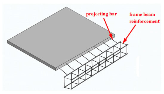
Figure 1.
Clash between the projecting reinforcement of the precast slab and frame beam reinforcement during hoisting.
Recent years have seen extensive domestic and international research on mitigating the interference caused by projecting reinforcement at precast slab ends. Two principal solution strategies have emerged—(i) non-projecting reinforcement details at precast slab ends for the bottom (precast) layer [8,9,10,11] and (ii) separated or discontinuous joint details (“segmented” or “split” joints) [12,13,14,15,16,17,18,19,20,21,22]—with numerous studies evaluating their structural performance. Zhang Jiajun [23], drawing on relevant Chinese and U.S. standards, established possible shear failure modes at the composite slab end and proposed corresponding shear capacity formulations. Parametric case studies indicated that the slab-end shear capacity can be ensured by adjusting the cast-in-place topping thickness, the overall reinforcement ratio of the composite slab, and by providing shear-resisting reinforcement across the interface. Provided that the slab end possesses adequate shear capacity, the longitudinal reinforcement at the slab end need not project beyond the precast unit. Zhang Xuefeng [24] proposed a closely butted composite slab system with non-projecting reinforcement on all four sides. Through in situ loading tests benchmarked against cast-in-place slabs, the study compared global and sectional responses. The results showed that the four-edge, non-projecting, closely butted composite slabs exhibited higher cracking load and superior flexural stiffness relative to conventional cast-in-place composite slabs. Liu Wei et al. [25] introduced an L-shaped groove, non-projecting composite slab detail, in which L-shaped recesses are formed at slab ends to accommodate edge and inter-slab connection reinforcement, thereby eliminating projecting bars. Full-scale load tests demonstrated that the overall mechanical performance of the L-groove non-projecting composite slab is comparable to that of traditional composite slabs and satisfies code requirements.
Relevant codes and standards [26,27,28] have also permitted indirect lap-type mechanical connections for precast slabs without projecting bars. However, these provisions typically require a cast-in-place topping thickness not less than 100 mm and not less than 1.5 times the precast slab thickness. Such requirements substantially increase floor dead load, which in turn amplifies seismic actions on the overall structure and necessitates additional reinforcement in slabs and beams. The resulting material and structural penalties render these solutions uneconomical and hinder their widespread adoption in practice.
To address these challenges, this paper proposes a grooved connection for truss-reinforced concrete composite slabs (see Figure 2). In this configuration, the longitudinal bars of the precast slab do not extend beyond the slab end. Instead, the slab end is cast in the factory with a profiled, recess–protrusion geometry; the longitudinal bars remain exposed within the recess. Additional stub “strengthening” bars are pre-embedded within the recess region, with a total area not less than that of the longitudinal bars located over the protruding portion at the precast bottom slab end that would otherwise not extend into the support. After hoisting and alignment, the additional bars are extended using parallel-thread couplers (straight-thread sleeves). Concurrently, short longitudinal bars are arranged within the recess and are tied/lapped to the bottom slab longitudinal bars. Both the extended additional bars and the short longitudinal bars are anchored into the support by a length not less than 5d (d = diameter of the respective longitudinal bar) and pass beyond the support centerline. To enhance force transfer reliability, short transverse bars are provided within the recess as construction detailing. All other fabrication and erection procedures remain consistent with those of conventional truss-reinforced concrete composite slabs. Because no bars project from the slab ends, on-site hoisting efficiency is markedly improved.
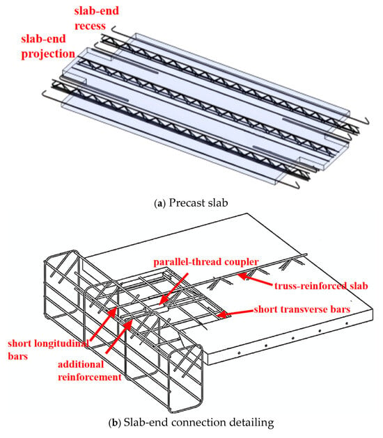
Figure 2.
Schematic of the grooved slab-end connection for precast slabs.
This study targets the following scientific issues: (i) the interface shear transfer and its post-cracking degradation for end connections without projecting bars; (ii) the force-sharing mechanism and ductility contribution of supplementary reinforcement and short bottom bars across different flexural stages; (iii) the effects of internal force redistribution in a two-span system on crack development and deflection evolution; and (iv) the safety reserve arising from the coupled shear–flexure resistance at the ends. To this end, the flexural performance under vertical loading of truss-reinforced concrete composite slabs employing grooved end-connections at the precast panel ends was investigated. Following prior studies on the flexural behavior of composite slabs [29,30,31,32,33,34,35], a full-scale two-span specimen was fabricated. By applying vertical loads on the slab surface, the failure mode, crack progression, load-carrying capacity, deflection, and reinforcement strains were systematically monitored to assess conformity with code-based calculations and to elucidate the end-force transfer path, thereby providing a basis for implementing this novel connection configuration in engineering practice.
2. Test Overview
2.1. Specimen Design
This study focuses on the global flexural performance of truss-reinforced concrete composite slabs employing grooved connections. A full-scale two-span test under static uniformly distributed surface loading was conducted to evaluate the load-carrying capacity, cracking behavior, and ductility of the connection under conventional vertical loading. As shown in Figure 3, the specimen consists of two equal-span composite slabs, a middle (interior) beam, and an edge (exterior) beam, and is designed as a one-way slab. The support at the middle beam simulates a fixed (encastre) restraint for the slab, while the support at the edge beam simulates a pinned restraint. Both the precast slab and the cast-in-place topping are 60 mm thick, giving a total composite slab thickness of 120 mm. Each individual composite slab has a span of 3300 mm and a width of 1500 mm. The overall span of the specimen is 7400 mm, with a width of 1500 mm. The bottom longitudinal reinforcement and the distribution reinforcement in the precast slab, as well as the distribution reinforcement in the topping, are C8@200. The topping’s support (negative-moment) reinforcement is C8@120. Additional strengthening bars are C16. The short longitudinal bars are of the same specification as the precast slab’s main reinforcement, and the short transverse construction bars are C6.
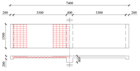
Figure 3.
Specimen dimensions drawing.
2.2. Material Properties
The specimens were produced using C30 ready-mixed concrete. From the same batch, two sets of twelve 100 mm cubic concrete specimens were reserved—six from the cast-in-place topping and six from the precast slab—and cured under the same conditions as the test specimens. Tests on concrete material properties were carried out in accordance with the Standard for Test Methods of Physical and Mechanical Properties of Concrete (GB/T 50081-2019) [36]. The measured values were converted as specified, and the results are reported in Table 1.

Table 1.
Mechanical properties of concrete.
HRB400 reinforcing bars were employed. Tensile tests on the reinforcing steel were conducted in accordance with Metallic Materials—Tensile Testing—Part 1: Method of Test at Room Temperature (GB/T 228.1-2021) [37]. The corresponding material property results are presented in Table 2.

Table 2.
Mechanical properties of reinforcing steel.
2.3. Specimen Fabrication
The precast slabs were fabricated first, then transported to the test site for assembly and casting of the topping. The specimens were cured periodically until the concrete reached 100% of the design strength. The fabrication process of the specimen is shown in Figure 4.
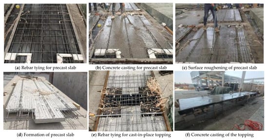
Figure 4.
Fabrication process of the specimen.
Two rolling pinned supports were arranged beneath the edge beam of the specimen, as shown in Figure 5. Each support consisted of two steel plates measuring 1500 mm × 200 mm and a steel tube of Φ75 mm filled with concrete; two C16 shear dowels were welded to the upper steel plate of the support.
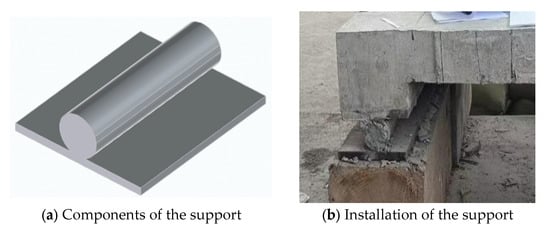
Figure 5.
Rolling pinned support.
2.4. Test Setup and Loading Protocol
The loading scheme followed the Standard for Test Methods of Concrete Structures (GB/T 50152-2012) [38]. Sandbags were used to simulate the vertical surface load on the slab, with each bag weighing 0.35 kN. After partitioning the slab surface, the sandbags were uniformly distributed across the entire surface of the two spans. The sandbags were placed with a planned spacing of 500 mm × 500 mm, leaving gaps between bags to prevent anti-arching, and stacked layer by layer until the target load was achieved, as shown in Figure 6. Prior to formal loading, preloading was conducted to check the condition of the instruments. During formal loading, the two spans were loaded synchronously. The loading stages and corresponding load values are given in Table 3.
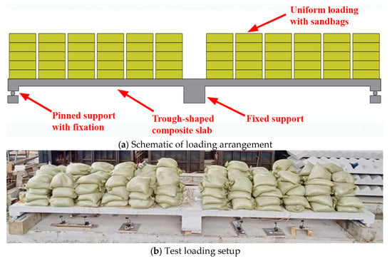
Figure 6.
Loading of the specimen.

Table 3.
Loading stages and corresponding loads.
Loading was terminated when any of the following conditions were met: (1) crushing of concrete in the compression zone within the span; (2) maximum soffit deflection reaching 66.6 mm (L/50); (3) maximum crack width at the slab soffit reaching 1.5 mm; or (4) fracture of the main tensile reinforcement or tensile strain reaching 0.01.
2.5. Instrumentation Layout
Reinforcement strains were recorded using an XL2118BX static strain indicator, with strain gauges on the rebars arranged as shown in Figure 7. Two dial gauges were installed along the short-span direction of the specimen at midspan (L/2) and at 3/8 span at the slab soffit, as shown in Figure 8.
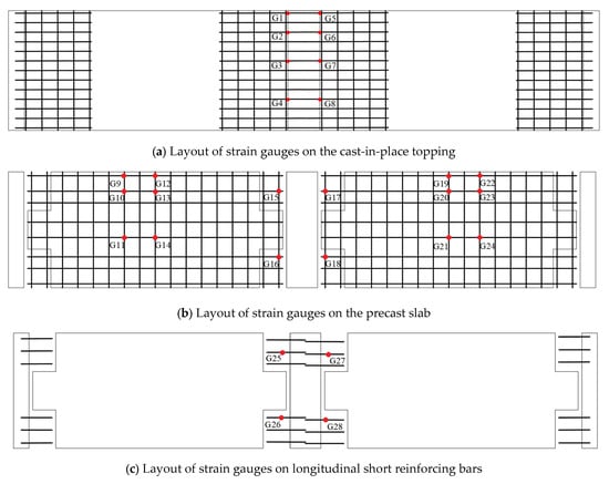
Figure 7.
Arrangement of strain-gauge measurement points.

Figure 8.
Arrangement of displacement gauges at the slab soffit.
3. Results
3.1. Crack Patterns
The crack patterns of the specimens are shown in Figure 9 and are predominantly flexural in nature. Crack development proceeded through three stages:
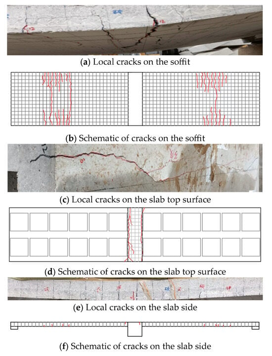
Figure 9.
Crack schematics.
Stage I: Prior to reaching the cracking load, no visible cracks appeared, and the slabs behaved elastically.
Stage II: At the cracking load, initial cracks penetrated the tensile zone and became through-cracks. With further loading, both the number and width of cracks increased, and cracks propagated upward along the slab sides, eventually reaching the vicinity of the composite interface.
Stage III: The number of cracks stabilized, while crack widths continued to increase, with a noticeably higher growth rate than in Stage II.
The longest through-crack on the slab surface was approximately 75 mm, and the maximum crack width reached 1.66 mm. Cracks were relatively uniformly distributed near the junctions of the central rib and in regions between 1/2 and 3/8 of the span along the soffit and slab sides. These observations indicate a typical flexural cracking pattern for composite slabs, with crack initiation at regions of maximum tensile stress and subsequent stable crack propagation governed by tension stiffening and interface restraint.
Additional Remarks for Clarity
The transition from Stage II to Stage III coincided with the formation of a stable crack pattern and the onset of more pronounced stiffness degradation.
The tendency of cracks to approach the composite interface suggests effective load transfer through the interface; however, increased crack width in Stage III implies reduced tension-stiffening contribution of concrete as steel strain grows.
3.2. Load–Deflection Response
As shown in Figure 10, the load–deflection curves exhibit a characteristic tri-linear trend.
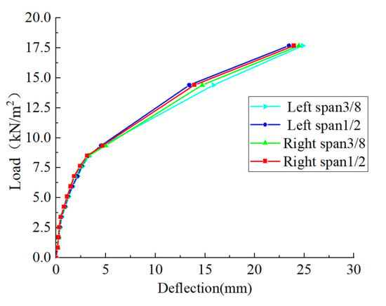
Figure 10.
Load–deflection.
Stage I: Before Load Level 5 (4.25 kN/m2), deflection increased linearly with load. No cracking was observed at either the slab ends or midspan; the composite slab behaved elastically.
Stage II: Between Load Levels 5 and 10 (4.25–8.5 kN/m2), an inflection point appeared, and the response became nonlinear with a reduced slope, indicating the onset and progression of cracking.
Stage III: Beyond Load Level 11 (≥9.35 kN/m2), deflection increased nonlinearly with a new inflection point, corresponding to service-stage behavior with cracking of the soffit concrete. Relative to Stage II, both the deflection growth rate and the crack development rate increased significantly.
Loading was terminated upon reaching the predefined serviceability limit; at that time, the specimen had not fully entered the plastic stage. Hence, both ultimate deflection and ultimate load retained a reserve margin, evidencing pronounced deformation capacity. Overall, the grooved connection composite slab displayed favorable global flexural performance and ductility.
3.3. Reinforcement Strain Analysis
Strain gauges were installed at critical sections with adverse bending effects and at locations with bar geometry transitions near the slab ends. The load–strain curves are presented in Figure 11, allowing assessment of the reinforcement stress state throughout loading.
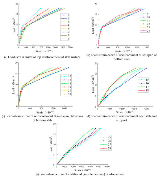
Figure 11.
Load–reinforcement strain curves.
Figure 11a–c, top and bottom reinforcement: The responses are broadly tri-linear. In the initial loading range, steel strains increased linearly with load. After cracking, strain growth accelerated due to reduced tension stiffening of concrete. Once yielding was initiated, the apparent strain growth rate with respect to load diminished, reflecting stress redistribution and localization of plasticity in yielded zones.
Figure 11d–e, bottom slab end bars and additional reinforcement: According to the plane-sections assumption, at the member end under bending, fibers above the neutral axis are in tension, and those below are in compression. The bottom-end bars and the additional bars were positioned in the compressive zone. After concrete cracking, the height of the compression zone decreased, causing these bars to engage in compression. Their load–strain responses remained approximately linear within the measured range. At Load Level 13, the microstrain in the additional bar was approximately −500 με, compared with −175 με in the bottom-end bar, indicating that the additional reinforcement carried the predominant compressive force.
Comparative note: The load–strain evolution of the top and bottom bars is broadly consistent with the trends reported by Liu Zengcheng [39] for cast-in-place slabs, supporting the similarity in fundamental flexural behavior. The end bends provided for the additional bars effectively limited relative slip at the composite interface, preventing bar pullout and premature failure. As the load increased and the bottom slab transitioned from elastic to plastic response, the additional bars contributed significantly to compressive force transfer and overall rotational capacity. These findings elucidate the force transfer mechanism of the grooved connection, highlighting the roles of interface restraint and additional reinforcement in sustaining composite action after cracking.
3.4. Comparative Analysis of Load Values
Considering the self-weight and related conditions of the grooved connection composite slab, the load-carrying capacity was calculated using the design equations of the Code for Design of Concrete Structures [40] (GB 50010-2010); see Table 4.

Table 4.
Comparison of load-carrying capacities.
Treating the slab as a one-stage composite member, the cracking loads at the top surface over the supports and at the soffit were computed per the same code; see Table 5.

Table 5.
Comparison of cracking loads.
The measured cracking load at the top surface over the supports agrees well with the calculated value, whereas the measured soffit cracking load is lower than the prediction. From the standpoint of elastic analysis, once cracking occurs at the intermediate support during testing, internal forces are redistributed, causing the tension zone at the soffit to reach the cracking condition earlier; consequently, the actual soffit cracking load is lower than the theoretical value.
4. Discussion
4.1. Failure Mechanism Analysis
Under vertical loading, the specimens exhibited a typical flexural response that can be divided into three stages. In the elastic stage (prior to approximately 4.25 kN/m2, applied via sandbags), both concrete and reinforcement strains were small, and the load and deflection remained limited. The onset of concrete cracking marked the beginning of the elastic–plastic stage (about 4.25–8.5 kN/m2). With increasing load, flexural cracks initiated at the soffit, propagated along the spanwise direction, increased in number, and extended toward both side edges. The plastic stage (beyond about 9.35 kN/m2) was characterized by a slow increase in load accompanied by rapid growth in deformation. In this stage, the number and width of soffit cracks increased markedly, the slab underwent large deflections, and loading was stopped when the preset deflection limit was reached. At termination, the applied load was 17.68 kN/m2. The slope of the load–deflection curve had not begun to degrade, indicating that additional load-carrying capacity remained.
To elucidate the ultimate failure mode, after reaching the termination criterion, the specimen was subjected to a one-step heavy ballast load (22.20 kN/m2) until complete loss of load-carrying capacity. The specimen failed in a ductile flexural manner governed by tensile yielding of the bottom reinforcement (Figure 12). The top concrete did not crush, the specimen experienced large deformations without rupture, and no shear failure occurred at the slab ends. Side cracks were predominantly vertical, initiating at the soffit and extending upward to the top surface. Cracks were continuous across the composite interface, which maintained a good bond with no separation between the precast base slab and the cast-in-place topping. These observations indicate that the roughened interface provided sufficient shear transfer to meet load-carrying requirements.
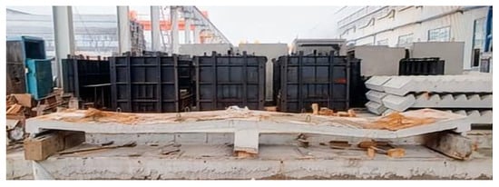
Figure 12.
Final failure mode of the specimen(s).
Based on the test phenomena and crack evolution, the crack development pattern and failure mode of the two-span grooved connection composite slab are similar to those of a conventional cast-in-place one-way slab. The internal force distribution is also analogous to that of a cast-in-place slab, with negative moment zones over the interior support and positive moment zones within the spans behaving in a comparable manner.
4.2. Risks and Limitations
Loading-type limitations: The present study considers only static, uniformly distributed vertical loading; cyclic loading and in-plane shear coupling due to seismic actions are not covered. Low-cycle fatigue in the grooved connection region and the hysteretic energy dissipation capacity of the coupler connections require dedicated testing.
Insufficient parameter coverage: Systematic parametric analyses were not conducted for material grade, reinforcement ratio, interface roughness, topping thickness, or anchorage length. The conclusions are therefore applicable only within the parameter domain adopted in this study.
Constructability sensitivity: The performance is sensitive to the anchorage quality of straight-thread couplers and short bars. Field deviations—such as insufficient coupler tightening torque and bar misalignment—may affect interface composite action and crack control.
Scale and boundary effects: Although the boundary conditions of the two-span one-way slab approximate engineering practice, they remain a laboratory equivalent. Caution is advised when extrapolating to complex frames, slab openings, or layouts with dense secondary beams.
4.3. Comparative Analysis with Existing Studies
Addressing the long-standing issue of projecting reinforcement in conventional composite slabs, this section contrasts two prevalent solutions reported in the literature—L-shaped grooves without projecting bars and separated (split) joints—with the proposed groove-type connection. The advantages and limitations are summarized in Table 6.

Table 6.
Scheme Comparison.
5. Conclusions
Addressing limitations in existing composite slab technologies, a channel-type end-connection detail for truss-reinforced composite slabs was proposed and evaluated through flexural testing. The following conclusions were drawn:
- (1)
- Compared with conventional protruding-rebar (dowel) composite slabs, the proposed grooved connection system optimizes slab geometry and the lapping/anchorage of additional reinforcement. The experimental results verify the feasibility of the grooved connection composite slab configuration.
- (2)
- The new configuration satisfies relevant code requirements for load-carrying capacity. Its failure mode and crack evolution are comparable to those of conventional cast-in-place one-way slabs, demonstrating favorable global performance and deformation capacity.
- (3)
- Under the design load, the measured midspan deflection was L/110, which is less than the code limit of L/50. The measured serviceability load capacity was 11.35 kN/m2, exceeding the design value of 10 kN/m2 and indicating a margin of safety.
Overall, the truss-reinforced concrete composite slabs employing grooved connection between precast panels exhibit safe and reliable flexural behavior under vertical loading. The connection detail is also straightforward for on-site construction, facilitating practical implementation. Future work should focus on the in-plane shear performance of this connection under seismic actions to clarify its behavior and to inform design provisions for earthquake-resistant applications.
Author Contributions
Conceptualization, T.L. and Q.G.; methodology, T.L. and R.W.; preparation of the experiments, R.W., J.L. and G.L.; resources, T.L. and Q.G.; experiment, R.W. and J.L.; writing—original draft preparation, T.L. and J.L.; writing—review and editing, G.L.; funding acquisition, T.L. All authors have read and agreed to the published version of the manuscript.
Funding
This work was supported by the Shaanxi Key R&D Program (Grant No. 2024SF-YBXM-637), the National Natural Science Foundation of China (Grant No. 52308204), the China Postdoctoral Science Foundation (Grant No. 2025M773235), the Beijing Postdoctoral Research Foundation (Grant No. 2025-ZZ-42), and the Scientific Research Foundation of China National Machinery Industry Corporation Ltd. (Grant No. ZDZX2025-16).
Data Availability Statement
The data presented in this study are available on request from the corresponding authors. The data in this study are not publicly available due to restrictions in the project agreement.
Conflicts of Interest
Author Ting Liu was employed by the company China United Northwest Institute for Engineering Design & Research Co., Ltd. Author Ruixuan Wang was employed by the company Jinduicheng Molybdenum Industry Group Co., Ltd. The remaining authors declare that the research was conducted in the absence of any commercial or financial relationships that could be construed as a potential conflict of interest. The authors declare that this study received funding from the Scientific Research Foundation of China National Machinery Industry Corporation Ltd. The funder was not involved in the study design, collection, analysis, interpretation of data, the writing of this article, or the decision to submit it for publication.
References
- Ferdous, W.; Bai, Y.; Ngo, T.D.; Manalo, A.; Mendis, P. New advancements, challenges and opportunities of multi-storey modular buildings—A state-of-the-art review. Eng. Struct. 2019, 183, 883–893. [Google Scholar] [CrossRef]
- Qi, Y.; He, X.; Li, Y.; Jia, Y. Threshold effect study on the development of prefabricated buildings for energy conservation and emission reduction in the construction industry. Sci. Rep. 2025, 15, 27269. [Google Scholar] [CrossRef]
- Roxas, C.L.C.; Bautista, C.R.; Dela Cruz, O.G.; Dela Cruz, R.L.C.; De Pedro, J.P.Q.; Dungca, J.R.; Lejano, B.A.; Ongpeng, J.M.C. Design for Manufacturing and Assembly (DfMA) and Design for Deconstruction (DfD) in the Construction Industry: Challenges, Trends and Developments. Buildings 2023, 13, 1164. [Google Scholar] [CrossRef]
- Dou, Y.; Sun, X.; Ji, A.; Wang, Y.; Xue, X. Development strategy for prefabricated construction projects: A tripartite evolutionary game based on prospect theory. Eng. Constr. Archit. Manag. 2023, 30, 105–124. [Google Scholar] [CrossRef]
- Zhu, J. Significance and Challenges of Prefabricated Building Development. Sustain. Environ. 2024, 9, 100. [Google Scholar] [CrossRef]
- Deng, F. Research on the Construction and Development of Prefabricated Building Industry Chain from the Perspective of Ecological Niche. Front. Econ. Manag. 2025, 6, 271–278. [Google Scholar] [CrossRef]
- JGJ 1-2014; Technical Specification for Prefabricated Concrete Structures. China Architecture & Building Press: Beijing, China, 2014.
- Xiao, Y.; Li, X. Experimental study on flexural performance of a new no-extension joint composite slab. Build. Struct. 2023, 53, 83–89. (In Chinese) [Google Scholar] [CrossRef]
- Sun, P. Study on Mechanical Behavior of End Bearing of Reinforced Truss Laminated Slab. Master’s Thesis, Tsinghua University, Beijing, China, 2019. (In Chinese). [Google Scholar] [CrossRef]
- Cai, B.; Li, B.; Zhao, L. Reliability analysis of shear capacity of RC composite slabs. Concrete 2017, 166–168+172. (In Chinese) [Google Scholar] [CrossRef]
- Liu, H.; Wang, Z.; Du, X.; Shen, G.Q. The seismic behaviour of precast concrete interior joints with different connection methods in assembled monolithic subway station. Eng. Struct. 2021, 232, 111799. [Google Scholar] [CrossRef]
- Liu, J.; Liu, Y.; Yu, D. Experimental and Numerical Studies on the Seismic Performance of New Assembled Concrete Frame Beam–Column Joints. Buildings 2023, 13, 329. [Google Scholar] [CrossRef]
- Shang, X.; Zheng, M.; Guo, Y.; Zhuang, L.; Liang, H. Experimental Investigation on Static Performance of Novel Precast Concrete Composite Slab–Composite Shear Wall Connections. Buildings 2025, 15, 1935. [Google Scholar] [CrossRef]
- Wang, X.; Yang, Q.; Peng, X.; Xia, K.; Xu, B. A Review of Mechanical Performance Studies on Composite Concrete Beams and Slabs. Materials 2025, 18, 3259. [Google Scholar] [CrossRef] [PubMed]
- Chen, X.; Luo, B.; Liu, X. Experimental and Numerical Investigation of a New Type of Composite Slab with a Separate Join. Buildings 2024, 14, 1890. [Google Scholar] [CrossRef]
- He, Q.; Wu, Y.; Hu, C.; Yang, K.; Yi, W. Experimental Study of the Two-Way Mechanical Behavior of Tightly Spliced Prestressed Reinforced Concrete Laminated Slab. J. Struct. Eng. 2025, 151, 04025063. [Google Scholar] [CrossRef]
- Chen, D.; Zhang, X.; Xu, S.; Fu, L.; Zhu, X.; Li, H. Deflection calculation method for tightly spliced composite two-way slabs. Build. Struct. 2023, 53, 68–74. (In Chinese) [Google Scholar] [CrossRef]
- Deng, S.; Dong, B.; Bi, Q.; Wei, B.; Lei, Y.; Wu, J.; Xu, M. Direct shear performance and engineering application of tight-jointed composite slab seams. Build. Struct. 2022, 52, 7–14. (In Chinese) [Google Scholar] [CrossRef]
- He, Q.; Hu, C.; Yang, K.; Yi, W. Joint configuration and mechanical performance of tight-jointed composite slabs: Experimental study. J. Hunan Univ. Nat. Sci. 2022, 49, 111–122. (In Chinese) [Google Scholar] [CrossRef]
- Xiao, T.; Zhang, M.; Li, B.; Xu, Q.; Gong, S. Flexural performance of composite slab side-groove joints: Experimental study. J. Zhejiang Univ. Eng. Sci. 2023, 57, 842–854. (In Chinese) [Google Scholar] [CrossRef]
- Li, W.; Han, J.; Li, Y.; Zhao, W.; Chen, S.; Dai, A.; Qiang, X.; Shu, C. Long-term cracking resistance of tight-jointed truss-reinforced concrete composite slabs under sustained load. J. Build. Struct. 2025, 46, 43–50. (In Chinese) [Google Scholar] [CrossRef]
- Lin, Y.; Ni, H.; Zhao, Z.; Zhou, X. Flexural performance of slotted tight-jointed steel tube truss concrete composite slabs. China Civ. Eng. J. 2025, 58, 38–49. (In Chinese) [Google Scholar] [CrossRef]
- Zhang, J.; Zheng, Y.; Zhao, Y. Shear capacity analysis at slab ends of concrete composite slabs. Concr. Cem. Prod. 2015, 67–70. (In Chinese) [Google Scholar] [CrossRef]
- Zhang, X.; Zheng, S.; Shan, Y.; Zhou, X.; Chen, D. In-situ comparative loading test on tightly spliced no-extension two-way composite slabs. Build. Struct. 2019, 49, 113–117. (In Chinese) [Google Scholar] [CrossRef]
- Liu, W.; Guo, X.; Wen, Y.; Wang, B.; Zhou, S.; Xu, J.; Dai, K. Full-scale tests on load-bearing performance of L-shaped slot no-extension composite slabs. Eng. Sci. Technol. 2024, 57, 213–221. (In Chinese) [Google Scholar] [CrossRef]
- T/CECS 715-2020; Technical Specification for Application of Truss-Reinforced Concrete Composite Slabs. China Architecture & Building Press: Beijing, China, 2020.
- 15G310-1; Details for Connections in Prefabricated Concrete Floors and Stairs. China Planning Press: Beijing, China, 2015.
- JGJ/T 258-2011; Technical Specification for Ribbed Precast Concrete Composite Floor Slabs. China Architecture & Building Press: Beijing, China, 2011.
- Zhang, M.; Lv, H.; Jiang, Q.; Wu, Y.; Yang, Y.; Dai, H. Study on flexural behavior of laminated slabs constructed with composite limestone powder-tailings mixed sand concrete. Structures 2025, 77, 109169. [Google Scholar] [CrossRef]
- Liu, J.; Hu, H.; Li, J.; Chen, Y.F.; Zhang, L. Flexural behavior of prestressed concrete composite slab with precast inverted T-shaped ribbed panels. Eng. Struct. 2020, 215, 110687. [Google Scholar] [CrossRef]
- Lu, L.; Gao, M.; Guo, Y.; Wang, W.; Yan, H. Experiments on flexural behavior of the prefabricated RAC and NWC composite slab. Ain Shams Eng. J. 2022, 13, 101789. [Google Scholar] [CrossRef]
- Wu, H.; Qiao, G.; Qiao, Y.; Zhong, Z.; Zhou, Z.; Ye, T. Experimental and theoretical research on flexural performance of truss reinforced concrete two-way composite slab with prefabricated baseplate. Structures 2023, 58, 105470. [Google Scholar] [CrossRef]
- Luo, B.; Tang, Z.; Du, T.; Song, Y.; Cao, G. Experimental study on flexural performance of composite slab with UHPC layer. Constr. Build. Mater. 2025, 492, 143023. [Google Scholar] [CrossRef]
- Chen, X.; Luo, B.; Lou, F.; Chen, Z. Experimental and numerical investigation on the flexural behavior of a novel composite slab with a joint. Adv. Struct. Eng. 2024, 27, 2429–2443. [Google Scholar] [CrossRef]
- Jiang, Y.; Liu, L.; Wang, X.; Liu, R.; Yang, H. Study on Bending Performance of High-Ductility Composite Slab Floor with Composite Ribs. Materials 2025, 18, 658. [Google Scholar] [CrossRef]
- GB/T 50081-2019; Standard for Test Methods of Physical and Mechanical Properties of Concrete. China Architecture & Building Press: Beijing, China, 2019.
- GB/T 228.1-2021; Metallic Materials—Tensile Testing—Part 1: Method of Test at Room Temperature. China Standards Press: Beijing, China, 2021.
- GB/T 50152-2012; Standard for Test Methods of Concrete Structures. China Architecture & Building Press: Beijing, China, 2012.
- Liu, Z. Study on the Mechanical Properties of the Bearing Joints and Floor of New Type of Unilateral Reinforced Composite slab. Master’s Thesis, China University of Mining and Technology, Xuzhou, China, 2024. (In Chinese). [Google Scholar] [CrossRef]
- GB 50010-2010; Code for Design of Concrete Structures. China Architecture & Building Press: Beijing, China, 2011.
Disclaimer/Publisher’s Note: The statements, opinions and data contained in all publications are solely those of the individual author(s) and contributor(s) and not of MDPI and/or the editor(s). MDPI and/or the editor(s) disclaim responsibility for any injury to people or property resulting from any ideas, methods, instructions or products referred to in the content. |
© 2025 by the authors. Licensee MDPI, Basel, Switzerland. This article is an open access article distributed under the terms and conditions of the Creative Commons Attribution (CC BY) license (https://creativecommons.org/licenses/by/4.0/).