Abstract
This paper presents a case study on an ultra-deep excavation in a reclaimed area supported by servo steel struts, addressing the limited case-specific data on deformation behavior under such complex geological conditions. Comprehensive monitoring of the pit structure and surrounding environment was performed throughout construction. Results highlight significant time-dependent deformation due to the rheological behavior of artificial fill and soft soil, with metro tunnel displacement during suspension phases contributing up to 29% of the total. Servo steel struts, via active axial force compensation, reduced maximum diaphragm wall displacement by 24%, ground settlement by 29%, and pipeline settlement by 46% compared to conventional supports. Integrated measures, including bottom-sealed diaphragm walls, isolation piles, and grouting curtains, successfully confined tunnel deformation within 5.4 mm, complying with strict safety criteria. A strong linear correlation between tunnel and wall displacements was observed, enabling a predictive envelope model for deformation. This study underscores the efficacy of servo steel struts in controlling excavation-induced deformation in reclaimed areas and offers practical insights for designing and managing ultra-deep excavations in similar challenging settings.
1. Introduction
In recent years, accelerated urbanization in China has led to coastal cities like Shenzhen facing severe challenges of land resource scarcity. Consequently, land reclamation has become a crucial approach to expand urban space [1]. Reclaimed areas typically feature artificial fill strata composed of incompletely consolidated soft soils, loose fills, and complex marine–terrestrial sedimentary layers. These strata exhibit poor mechanical properties, high compressibility, and significant rheological characteristics [2], which tend to induce significant deformation of foundation pits during construction, thereby threatening the safety and functionality of adjacent metro tunnels, underground pipelines, and building foundations.
In reclaimed areas such as Shenzhen’s Super Headquarters Base, deep excavations constructed in close proximity to metro lines have become commonplace. Within such complex environments, precise deformation control of foundation pits and ensuring the safety of surrounding infrastructure pose significant challenges for engineers and researchers. Deep excavations exert substantial influence on the deformation of adjacent metro tunnels [3]. Engineering practice in soft soil regions also demonstrates that deep excavations can trigger significant deformation responses in adjacent shallowly buried pipelines [4]. Furthermore, deep excavations with inadequate deformation control can adversely affect neighboring building foundations [5]. These studies collectively highlight the complexity and critical importance of deformation control in deep excavation projects and ensuring the safety of surrounding environments under challenging geological conditions.
Numerous field measurement studies have been conducted on the deformation patterns of foundation pits and adjacent underground structures during construction in natural strata. The research by Song et al. [6] demonstrated that the excavation of upper soil layers has a more significant impact on surrounding utility tunnels and soil masses. Focusing on a foundation pit in Shenzhen, Chen et al. [7] systematically explored the patterns of ground surface settlement induced by excavation and its influencing mechanisms on adjacent buildings. Through field measurement analysis of a zoned excavation in soft ground, Liang et al. [8] discussed the deformation response characteristics of adjacent metro stations and shield tunnels. Using a case study in Shanghai, China, Peng et al. [9] analyzed the influence of soft soil deformation caused by deep excavation on adjacent metro tunnels. They discovered strong linear correlations between tunnel displacement and retaining structure horizontal displacement, as well as between strut axial force and diaphragm wall horizontal displacement. Wang et al. [10] investigated the influence of foundation pit construction on adjacent metro tunnels in soft soils. They noted that piping phenomena caused by failed waterproofing measures significantly exacerbate tunnel deformation. Normalization analysis indicated a good linear relationship between tunnel vertical displacement and horizontal convergence, a weaker linear correlation between horizontal displacement and horizontal convergence, and the poorest correlation between vertical and horizontal displacements. Through field monitoring, Ni et al. [11] systematically analyzed the coupled effects of dewatering and excavation on the settlement of surrounding buildings. They identified the combined action of groundwater level changes and excavation unloading effects as the key factor causing differential settlement in buildings. Focusing on special ground conditions, Nicotera et al. [12] revealed the settlement distribution patterns of adjacent buildings induced by excavation through long-term monitoring of a deep excavation in pyroclastic soil and soft rock strata. They pointed out that the stiffness heterogeneity of the strata significantly influences building settlements around the excavation.
In the research field of servo steel struts, scholars have conducted systematic explorations using various methods, including numerical simulations, theoretical analysis, model tests, and field measurement analyses. In terms of numerical simulation, Li et al. [13] confirmed via numerical simulation that servo steel struts can effectively control the deformation of the retaining structure and the surrounding ground settlement induced by excavation. Nangulama et al. [14] achieved an optimized design for the axial force of servo steel struts through numerical simulation. Zhao et al. [15] investigated the influence of axial force variation in servo steel struts on the horizontal displacement of the retaining structure. At the theoretical analysis level, Di et al. [16] integrated non-limit earth pressure theory with the beam on elastic foundation method to propose a hybrid computational method combining an elastic foundation beam model with nonlinear optimization. This method can quantitatively determine multiple sets of optimal design axial forces for servo steel struts corresponding to different excavation steps, providing theoretical support for the dynamic design of servo strut systems. Li et al. [17] proposed a beam on elastic foundation method for calculating excavation deformation that considers the effect of servo steel struts, providing a key theoretical basis for predicting the deformation of retaining structures in excavations utilizing servo steel struts. Hu et al. [18], based on soil physico-mechanical parameters, excavation support structure parameters, and field monitoring data, employed various machine learning methods to predict the axial forces of steel struts in deep excavations and systematically compared the predictive performance of different models. This provides a feasible technical pathway for intelligent early warning and proactive control using servo struts in deep excavation engineering. However, this study has certain limitations: it did not analyze the deformation control effectiveness of servo steel struts on the surrounding sensitive environment, such as ground settlement, pipeline deformation, and adjacent metro tunnels, nor did it conduct research related to the spatiotemporal effects of the excavation, making it difficult to fully adapt to the practical requirements of complex engineering scenarios. Furthermore, research conducted through model tests has also made significant contributions. Model tests by Chen et al. [19] revealed that while increasing the axial force of servo steel struts effectively controls wall horizontal displacement, it leads to nonlinear growth in strut axial force, necessitating a balance between deformation control requirements and economic efficiency. Further model tests by Di et al. [20] found that increasing the length and axial force of internal struts significantly elevates earth pressure behind the wall at the strut location. Furthermore, coordinated adjustment of multiple struts provides better control over wall lateral displacement compared to independent adjustment of single struts, providing key parameter insights for optimizing servo steel strut system design. In terms of field measurement analysis, Di et al. [21] compared field monitoring data and found that conventional steel struts experience significant axial force loss during excavation, whereas servo steel struts can effectively avoid this issue through their active axial force compensation mechanism, thereby achieving superior deformation control. Li et al. [22], based on a historic building preservation case, pointed out that the loading of servo steel struts can significantly suppress lateral deformation of the retaining structure, but excessive active loads may induce tensile stress in upper struts. The foundation underpinning technique they proposed was proven highly effective in controlling the differential settlement of adjacent historic buildings. Field measurement studies by Nangulama et al. [23] demonstrated that the servo steel strut system, by dynamically adjusting strut axial force, can precisely control the bending moment and lateral deformation of the retaining structure within design limits, verifying its engineering applicability in complex strata.
The academic community has conducted extensive research on reclaimed soil, with relevant findings providing crucial support for understanding its rheological behavior. Regarding the intrinsic mechanisms of reclaimed soil settlement, Plant et al. [24], in their study of the Hong Kong New International Airport reclamation project, proposed that settlement primarily comprises three components: the primary consolidation of the underlying alluvial clay beneath the fill layer, long-term secondary compression, and creep within the reclamation fill itself. Jiang et al. [25] conducted further research on the long-term settlement of the Chek Lap Kok Airport reclamation area in Hong Kong, pointing out that significant settlement can still occur in reclaimed soil even over a decade after project completion, with the soil remaining in the primary consolidation process. Additionally, settlement in reclaimed areas is closely related to the characteristics of the reclamation materials, the thickness of the underlying soil layers, and their physical and mechanical properties. Yu et al. [26] investigated ground deformation in the Chongming East Shoal reclamation area of Shanghai using SBAS-InSAR technology and laboratory tests. Their results indicate that external factors such as building loads and human activities significantly exacerbate settlement in reclaimed areas, and the triggering effect of these factors on settlement is often more pronounced than the time-dependent evolution of reclaimed soil under natural conditions. Li et al. [27] analyzed the spatiotemporal characteristics of land subsidence in the Shanghai coastal reclamation area using PS-InSAR technology and found that soil consolidation is the core mechanism behind the subsidence. Furthermore, human activities such as the construction of new sea walls and surrounding engineering projects can alter local subsidence rates, while groundwater level fluctuations induced by tides and rainfall may also influence short-term settlement. Furthermore, Park et al. [28] studied ground subsidence induced by excavation in the Incheon City reclamation area, South Korea, using InSAR technology. Their analysis revealed that pile driving, foundation pit excavation activities, and rainfall within the reclaimed area are all significant contributors to surface settlement. It is noteworthy that Ma et al. [29] investigated the impact of deep foundation pit excavation in a reclaimed area on adjacent metro tunnel deformation. However, this study did not incorporate the effect of time factors, nor did it explore the rheological properties of the reclaimed soil, representing a certain limitation. In summary, existing research collectively indicates that reclaimed soil exhibits significant rheological properties, and its physical and mechanical properties are generally inferior to those of natural soil layers. Reclaimed soil is often in an under-consolidated state, meaning the consolidation process may not be complete even years after reclamation, leading to cumulative surface settlement over time. Human activities like engineering construction and natural factors such as rainfall can also locally influence this process.
However, existing research has predominantly focused on conventional foundation pit engineering in natural strata. There remains a relative scarcity of field measurement studies specifically addressing the deformation characteristics of ultra-deep foundation pits in reclaimed areas, along with a lack of targeted case studies on the application of servo steel struts under such special engineering geological conditions. In the field of reclaimed soil rheology, current findings primarily concentrate on its impact on surface settlement, while case studies investigating the interaction between the rheological properties of reclaimed soil and underground structures are relatively inadequate. Particularly, there is a lack of case studies examining the exacerbated deformation of adjacent metro tunnels during the suspension of ultra-deep foundation pit construction in reclaimed areas, caused by the rheological properties of the reclaimed soil. It is important to emphasize that strata in reclaimed areas generally exhibit engineering characteristics such as high compressibility, strong rheology, and significant anisotropy. These properties make deformation issues induced by ultra-deep foundation pit construction more complex and pose greater threats to the safety of surrounding underground structures. Therefore, based on full-cycle field measurement data from a typical ultra-deep foundation pit in a Shenzhen reclaimed area, this paper systematically reveals the deformation control effectiveness of servo steel struts in complex reclaimed strata. Combined with comprehensive prevention measures such as bottom-sealed diaphragm walls and isolation piles, a deformation prediction model for metro tunnels applicable to reclaimed areas is proposed. The study also evaluates the deformation of metro tunnels during construction suspension periods caused by the spatiotemporal effects of the foundation pit, dominated by reclaimed soil rheology. The research findings not only fill a critical gap in key field measurement studies in this area but also provide important theoretical support and practical references for the design and construction of ultra-deep foundation pits under similar geological conditions.
2. Project Overview
2.1. Site Description
The foundation pit studied in this paper is located in the Shenzhen Bay Super Headquarters Base, Nanshan District, Shenzhen City, Guangdong Province, China. According to the Shenzhen Sustainable Development Plan (2017–2030) [30], this area has been explicitly designated as a key project, requiring construction projects to adhere to green and low-carbon principles. Additionally, the plan emphasizes the need to establish a “smart and efficient transportation service system,” prioritizing the development of the rail transit network as a core task. It particularly highlights the area’s dense underground space and the intricate network of rail transit systems, bridges, and tunnels, which pose significant operational safety risks. This complexity demands refined control over engineering construction and mitigation of environmental disturbances to ensure long-term sustainability.
The ultra-deep foundation pit project underpinning this study, as a core construction project in the area, directly addresses the aforementioned sustainable development goals through its technical solutions and implementation outcomes: Firstly, by optimizing the support system design through methods such as the application of servo steel struts, it reduces resource consumption and ground disturbance during construction, minimizing the project’s impact on the surrounding ecology and environment. This aligns with the core requirements of the “Green Actions” outlined in the Plan. Secondly, through precise control of deformation in the foundation pit and surrounding infrastructure, it ensures the safe and stable operation of key rail transit lines such as Metro Lines 9 and 11. This provides critical engineering practice support for the realization of the “smart and efficient transportation service system” advocated in the Plan, thereby contributing to the sustainable operation of the regional transportation network.
The site was formed through land reclamation between 1990 and 2000 [1]. The study area encompasses the foundation pit and adjacent sections of the Metro Line 9 tunnel and the Metro Line 11 tunnel. The foundation pit measures approximately 118 m in the east–west direction and 74 m in the north–south direction, with an excavation depth of 42.35 m, making it the deepest foundation pit for building construction currently in China. The support system consists of diaphragm walls with struts. The Metro Line 9 and Line 11 tunnels are located north of the pit, with the closest tunnel approximately 5.5 m from the excavation. The tunnel crown depth ranges from approximately 12 m to 16 m. Multiple pipelines exist on the northern and western sides of the site. The site plan is shown in Figure 1.
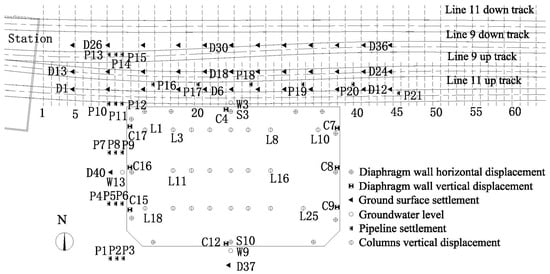
Figure 1.
Excavation pit plan and monitoring point layout diagram.
The core engineering risks are primarily manifested in three aspects: Firstly, the rheological properties of the reclaimed soil are prone to induce time-dependent continuous deformation, potentially exacerbating environmental disturbances in later stages. Secondly, ultra-deep excavation is liable to impose additional deformation loads on adjacent metro tunnels and underground pipelines, threatening the operational safety of infrastructure. Thirdly, failure of the waterproofing system could lead to abnormal fluctuations in the groundwater level around the foundation pit, further inducing soil instability and environmental deformation. The site plan shown in Figure 1 clearly delineates the excavation boundary, the alignment of the metro tunnels, and the locations of various monitoring points, providing a complete basis for the subsequent systematic analysis of the deformation behavior of the pit supporting structure and the surrounding environment.
2.2. Engineering Geology Conditions and Supporting System
The original geomorphological unit of the site was a coastal tidal flat. Following artificial filling, the original landscape features have been completely obliterated, resulting in a flat terrain. The strata distributed in the site from top to bottom in sequence are artificial fill, Holocene Series marine–terrestrial interbedded sedimentary layer of Quaternary System, Upper Pleistocene alluvial–pluvial sedimentary layer of Quaternary System, Quaternary residual layer, and Yanshanian coarse-grained granite and tectonic rock. The site’s groundwater primarily comprises pore water within the Quaternary deposits, including the Fill Layer, Marine–terrestrial Interphase Layer, Alluvial–Diluvial Layer, Residual Soil Layer, and Completely Weathered Rock, and fissure water within the bedrock. The physical and mechanical properties of each soil layer are presented in Table 1.

Table 1.
Physico-mechanical parameters of soils.
The excavation depth of the foundation pit is 42.35 m. The pit is supported by diaphragm walls in conjunction with struts. The diaphragm wall on the north side has a thickness of 1.5 m, while the diaphragm walls on the east, west, and south sides are 1.2 m thick. To control deformation of the adjacent metro tunnels, a row of isolation piles with a diameter of 1.2 m was installed externally along the north diaphragm wall. A total of eight levels of internal struts were installed. Among these, the 3rd to 7th levels of struts on the north side employed servo steel struts. These servo steel struts have a design bearing capacity of 5000 kN and a maximum stroke of 200 mm. Their axial force setpoints were 750 kN, 750 kN, 850 kN, 900 kN, and 1200 kN, respectively. Leveraging the advantage of active axial force compensation provided by the servo steel struts, the project optimized the original design. The initial scheme of nine fully reinforced concrete internal strut levels was revised to a hybrid support system comprising eight levels, which combines reinforced concrete struts with servo steel struts. This optimization, while ensuring the safety and stability of the support system, not only shortened the construction period but also reduced material consumption, effectively lowering the project’s economic cost. The support system layout and the servo steel strut system are illustrated in Figure 2 and Figure 3.
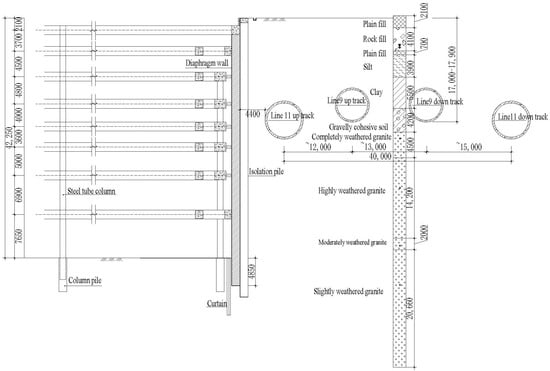
Figure 2.
Typical cross-section and geometry at site.
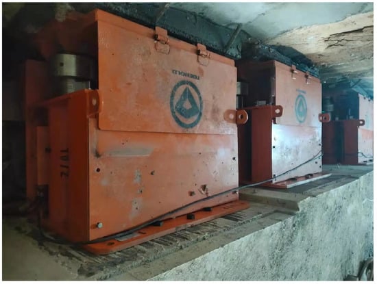
Figure 3.
Servo steel strut system.
During the excavation period, internal dewatering was implemented within the pit. To control potential bottom heave during excavation and stabilize the groundwater level outside the pit, thereby minimizing deformation of the adjacent metro tunnels, the foundation pit employed bottom-sealed diaphragm walls. The base of these diaphragm walls was embedded in the slightly weathered granite stratum. Simultaneously, a grouting curtain was installed beneath the diaphragm walls and within the fractured bedrock zone at the pit bottom. This measure severed the hydraulic connection between the interior and exterior of the excavation. The plan layout of the grouting curtain is shown in Figure 4.
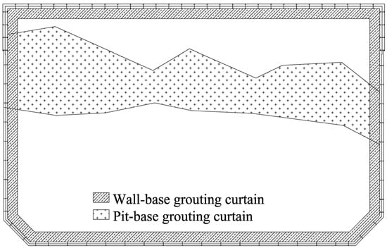
Figure 4.
Grouting curtain plan view.
Diaphragm walls were constructed prior to excavation. To minimize the soil disturbance caused by construction on the side adjacent to the metro tunnels north of the pit, a row of bored cast-in-place isolation piles was installed between the diaphragm wall and the metro, and a row of jet-grouted piles was installed on the inner side of the diaphragm wall, as shown in Figure 5. The isolation piles were drilled using a full-casing oscillator method, ensuring the casing remains embedded at least 2 m below the base of the hole; horizontal positioning tolerance was required to be within 50 mm, and verticality deviation shall not exceed 0.3%. No groundwater was pumped during the retaining structure construction. These measures effectively reduce the disturbance to the surrounding soil during diaphragm wall construction. The plan view of the isolation piles and jet-grouted piles is shown in Figure 5.
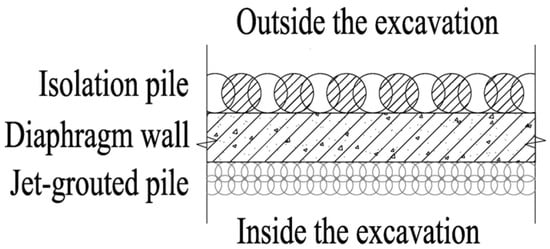
Figure 5.
Plan view of isolation piles and jet grouting piles.
2.3. Construction Procedure
Construction of the foundation pit began in March 2018. The construction sequence was as follows: first, the retaining system was completed, including the construction of the diaphragm walls, isolation piles, jet-grouted piles and micro-piles; then, grouting was carried out, including the curtain wall beneath the diaphragm walls and the grouting curtain within the fractured zone at the pit bottom; then, the foundation piles were constructed; finally, the pit was excavated to its bottom. After excavating to the pit bottom, construction of the foundation pit was suspended until 30 June 2023. During the construction process, if monitoring detected anomalies such as a sudden increase in deformation, unexpected settlement spikes, tunnel rebound events, etc., the construction team would immediately activate a real-time dynamic adjustment mechanism. This involved a dual approach: On one hand, based on monitoring data including strut axial forces and pit displacements, the axial forces of the servo steel struts were adjusted in real-time through methods like incremental loading or stepwise unloading. If deformation exceeded warning thresholds, emergency reinforcement of strut connections or the installation of additional temporary supports was implemented. On the other hand, the ongoing excavation activity was temporarily halted. The excavation zone was re-segmented by adopting a strategy of smaller segments, shorter advance lengths, and rapid support installation while also optimizing soil removal routes and material storage locations. Concurrently, the monitoring frequency was dynamically adjusted based on the deformation rate. If monitored values approached pre-set warning thresholds, graded response protocols were immediately triggered to ensure the safety of the foundation pit and the surrounding environment. Specific working conditions and the construction schedule are detailed in Table 2 and Figure 6.

Table 2.
Construction conditions.
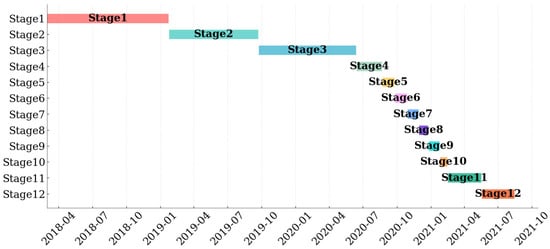
Figure 6.
Construction Schedule.
2.4. Instrumentation and Monitoring
The primary monitoring items for the foundation pit and tunnels investigated in this paper include the following: 1. horizontal displacement of diaphragm walls; 2. ground surface settlement; 3. vertical displacement of columns and diaphragm walls; 4. pipeline settlement; 5. horizontal displacement of metro tunnels; and 6. vertical displacement of metro tunnels. For Metro Line 9, the monitoring cross-sections start from chainage 1109. For Metro Line 11, the monitoring cross-sections start from chainage 8580. Cross-sections are spaced at 4.5 m intervals. The layout of foundation pit monitoring points and metro tunnel monitoring sections is shown in Figure 1.
All monitoring points adopted a default monitoring frequency of twice daily, which was dynamically adjusted based on the actual deformation conditions. If the deformation rate increased, the monitoring frequency was enhanced to strengthen dynamic tracking; conversely, if the deformation rate decreased, the frequency was appropriately reduced to balance monitoring efficiency with data timeliness. The monitoring accuracy for diaphragm wall horizontal displacement, ground surface settlement, and pipeline settlement is 0.01 mm, while for vertical displacement of columns and diaphragm walls and horizontal/vertical displacement of metro tunnels, it is 0.1 mm. During data analysis, based on the deformation response of all monitoring points throughout the entire construction process, points exhibiting significant deformation were selected as key subjects for analysis, with a focus on investigating the evolution of deformation patterns during the construction stages.
To ensure data reliability, all monitoring instruments underwent strict calibration and standardized installation prior to use. During the excavation period, regular accuracy checks and maintenance of the monitoring equipment were performed to minimize measurement errors. It should be noted that, as monitoring points could only cover specific areas of the foundation pit, surrounding ground, and metro tunnels, it is possible that monitoring points were not installed at the locations of maximum deformation. Consequently, the existing monitoring data might somewhat underestimate the actual maximum deformation of the foundation pit and the surrounding environment.
3. Result and Analysis
3.1. Horizontal Displacement of the Diaphragm Walls
Figure 7 shows the horizontal displacement of the diaphragm walls during the excavation process. Profile S3 represents the section supported by servo steel struts, whereas Profile S10 is supported by conventional struts. Positive displacement values indicate movement towards the excavation interior. It can be seen from the figure that the overall horizontal displacement of diaphragm walls on the north side is smaller than that on the south side. For the diaphragm walls on both the north and south sides, the displacement increment is significant when the cumulative excavation depth is within 20 m, and the displacement increment caused by subsequent excavation gradually decreases. An analysis was conducted to examine the progression of the maximum horizontal displacement location in the diaphragm walls during Stages 4 to 8, where the excavation depth was less than 20 m; the location of the maximum displacement on the north wall progressively moved downward with increasing excavation depth. This location stabilized in the subsequent excavation stages. Conversely, the location of the maximum displacement on the south wall continuously descended throughout the entire excavation process. This indicates that different support forms can significantly affect the position of the maximum horizontal displacement of the diaphragm walls. Comparing the deformation curves of Profiles S3 and S10 reveals that both exhibit a convex type. However, the deformation curve of Profile S3 exhibits a distinct “inflection” characteristic [31], which is markedly distinct from the smooth deformation curve observed in Profile S10.
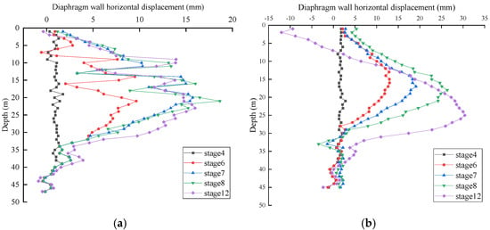
Figure 7.
Horizontal displacement of the diaphragm walls: (a) Profiles S3; (b) Profiles S10.
Figure 8 presents the fitting analysis results of excavation depth versus diaphragm wall horizontal displacement. Given the significant response of diaphragm wall displacement to excavation during Stages 4–8, the analysis focused on data from this period. The figure reveals that the ratio of maximum diaphragm wall horizontal displacement to excavation depth in the servo steel strut section ranged from 0.72‰ to 1.04‰, with an average value of 0.87‰. In contrast, this ratio for the conventional strut section ranged from 0.78‰ to 1.49‰, with an average of 1.14‰. This indicates an average reduction of 24% in horizontal displacement for the servo section compared to the conventional section. Statistical analysis by Zuo & Huang [32] of 19 deep excavation projects in the Shenzhen region showed that the ratio of maximum retaining structure horizontal displacement to excavation depth typically ranges from 0.5‰ to 2.0‰, with an average of 1.3‰. This comparison demonstrates that the horizontal displacement of the diaphragm walls in this pit falls well within the empirical range for the Shenzhen region. The above analysis confirms the significant advantage of servo steel struts over conventional struts. When the excavation depth is less than 20 m, under the same excavation depth, the active axial force compensation mechanism of servo steel struts can effectively restrain the horizontal displacement of diaphragm walls, reducing the deformation by 18% to 30% compared with diaphragm walls using traditional supports; when the excavation depth exceeds 20 m, servo steel struts can restrain the further downward movement of the position of the maximum horizontal displacement of the diaphragm walls.
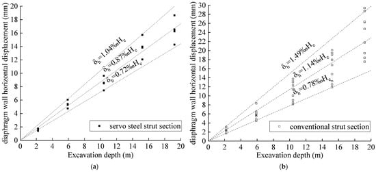
Figure 8.
Horizontal displacement of the diaphragm walls: (a) servo steel strut section; (b) conventional strut section.
3.2. Ground Surface Settlement
During the construction phase of the retaining system, systematic monitoring of ground surface settlement was conducted along the north side of the foundation pit. A total of 36 monitoring points (D1–D36) were arranged along the direction perpendicular to the foundation pit, which were divided into 3 monitoring sections: profile a (D1–D12), profile b (D13–D24), and profile c (D25–D36). The vertical distances from these sections to the foundation pit are 10 m, 20 m, and 35 m in sequence. Figure 9 shows the distribution of ground surface settlement along each profile, measured parallel to the diaphragm wall alignment, after completion of the diaphragm wall construction. Negative values indicate settlement. From the figure, it is evident that settlement occurred to varying degrees across all profiles, with greater magnitudes observed closer to the excavation. For profile a, the closest to the foundation pit, the settlement is characterized by larger settlement in the middle of the foundation pit and smaller settlement at the pit corners. This pattern aligns with findings by Roboski and Finno [33] regarding ground movement distribution parallel to deep excavations in clay. This consistency indicates that the ground disturbance generated during diaphragm wall construction exhibits a significant spatial effect. In contrast, profiles b and c, located farther from the pit, were not significantly influenced by this spatial effect.
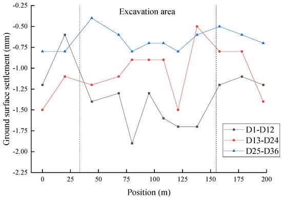
Figure 9.
Distribution of ground surface settlement after completion of the diaphragm wall construction.
Monitoring of ground surface settlement during the retaining system construction phase ended in May 2019. Settlement monitoring resumed during the excavation phase, commencing in August 2020. Consequently, deformation measured during the excavation phase does not include that induced by pre-excavation activities such as retaining system construction and foundation pile installation. Figure 10 illustrates the variation in ground surface settlement during the excavation period, where negative values indicate settlement. Analysis focused on monitoring points: D6 (midpoint, north side), D37 (midpoint, south side), and D40 (midpoint, west side). It can be seen from the figure that the settlement rate of the north-side monitoring point D6 increased significantly during Stages 6 to 9, while the increment of deformation slowed down after Stage 9 when the excavation depth exceeded 20 m. In contrast, the settlement of the south-side D37 and west-side D40 continued to accumulate throughout the entire excavation process. This indicates that servo steel struts significantly reduce the depth sensitivity of surface settlement during the ultra-deep foundation pit stage, where the excavation depth exceeds 20 m.
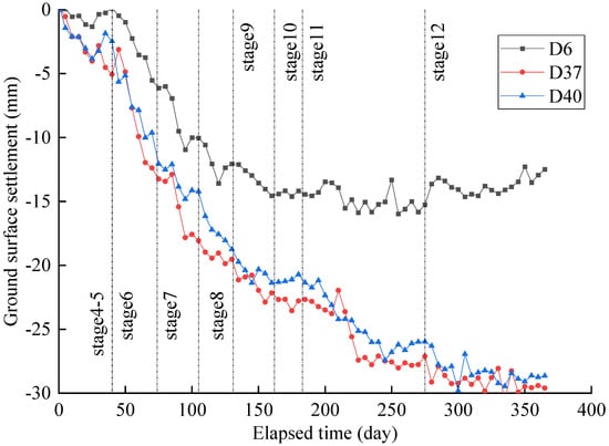
Figure 10.
Development of ground surface settlement at different construction stages.
Figure 11 presents the statistical analysis results of ground surface settlement for monitoring points located approximately 10 m from the pit near its central zone. Given the significant settlement response on the north side during excavation Stages 4–9 (cumulative depth ≤ 22.2 m), the analysis focused on data from this period. For the south and west sides, settlement data encompassing the entire excavation cycle (Stages 4–12, cumulative depth 42.35 m) was included. Quantitative analysis reveals: In the servo steel strut section, the ratio of settlement to excavation depth ranged from 0.347‰ to 0.686‰, with an average of 0.574‰. In the conventional strut section, this ratio ranged from 0.703‰ to 1.19‰, with an average of 0.808‰. This represents an average reduction of 29% in settlement for the servo section compared to the conventional section. According to the empirical data for the Shenzhen region provided by Zuo & Huang [32], ground settlement induced by excavation typically ranges from 0.6‰ to 2.0‰, with a mean value of 1.4‰. The settlement control achieved in this foundation pit is notably superior to similar regional projects. Settlement in the servo section is 59% lower than the regional mean, while settlement in the conventional section also falls within the reasonable range permitted by specifications.
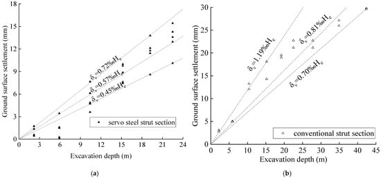
Figure 11.
Ground surface settlement: (a) servo steel strut section; (b) conventional strut section.
Remarkably, despite achieving the deepest excavation depth for similar pits in Shenzhen (42.35 m), this project maintained low ground settlement levels. This indicates highly effective control of settlement around the pit, primarily attributable to the synergistic effects of the following measures. The bottom-sealed diaphragm walls (embedded 4 m into the slightly weathered, low-permeability stratum) combined with high-pressure jet grouting curtains formed a fully enclosed water cutoff system, effectively severing the hydraulic connection between the excavation interior and exterior. As can be seen from Figure 12, the monitoring point with the largest groundwater level rise is W3, with a maximum rise of 1.52 m; the monitoring point with the largest groundwater level drop is W9, with a maximum drop of 2.72 m. During the entire excavation process, the groundwater level changed little, all within the project requirement that the groundwater level variation should not exceed 3 m. Therefore, the water-stop measures adopted in the foundation pit have reduced surface settlement. Isolation piles installed outside the retaining structure significantly reduced soil disturbance during excavation through their barrier effect. By pre-lowering the groundwater level within the pit, the compactness and shear strength of the base soil were enhanced, thereby reducing rebound deformation of the foundation soil and lateral displacement-induced settlement during the excavation stage.
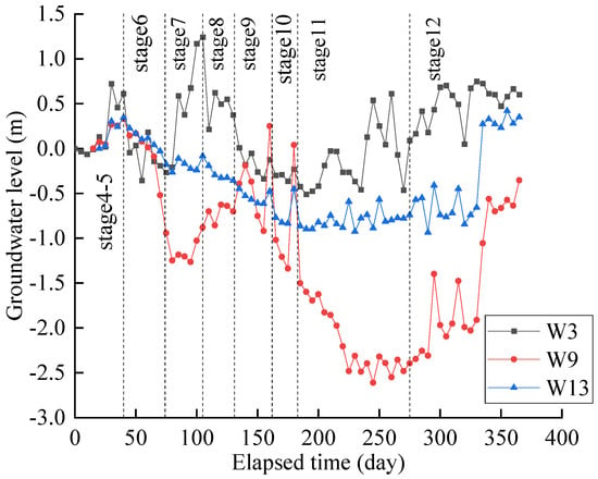
Figure 12.
Groundwater level at different construction stages.
The horizontal displacement of the diaphragm wall and the ground surface settlement are induced by overlapping factors, resulting in a significant correlation between them. The relationship between the horizontal displacement of the diaphragm wall and the ground surface settlement for both the servo strut section and the conventional strut section is shown in Figure 13. From the figure, it can be observed that the ratio of ground surface settlement to excavation depth in the servo strut section ranges from 0.42 to 0.89, with an average value of 0.63. In contrast, this ratio in the conventional strut section ranges from 0.59 to 1.02, with an average value of 0.77. These findings align with the statistical conclusions by Moormann et al. [34], which indicate that ground surface settlement in soft clay is typically 0.5 to 2 times the horizontal displacement of the retaining structure. For the same magnitude of horizontal displacement of the diaphragm wall, the ground surface settlement in the servo strut section is 18% lower than that in the conventional strut section. This difference primarily stems from the installation of isolation piles outside the diaphragm wall in the servo strut section, which effectively mitigates the disturbance to the soil outside the pit caused by the diaphragm wall.
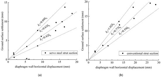
Figure 13.
Relationship between horizontal displacement of diaphragm walls and ground surface settlement: (a) servo steel strut section; (b) conventional strut section.
3.3. Vertical Displacement for Columns and Diaphragm Walls
Figure 14 illustrates the evolution of vertical displacement for columns and diaphragm walls along four monitoring sections during pit excavation: Section A (points C17, L1, L3, L4, L5, L6, L7, L8, L10, C7), Section B (points C16, L11, L12, L13, L14, L15, L16, C8), Section C (points C15, L18, L19, L20, L21, L22, L23, L24, L25, C9), and Section D (points C4, L6, L14, L22, C12). Analysis of the deformation of columns and diaphragm walls during the excavation stage reveals that in Stages 4–8, where the excavation depth is less than 20 m, the columns and diaphragm walls in all sections exhibit significant heaving deformation. This resulted from soil unloading within the pit due to excavation, triggering a base rebound effect. The upward soil movement was transmitted to the supporting structures via soil–structure interaction. Notably, during Stages 6–8, monitoring points located in the pit corner regions (e.g., C15, L18, L19) displayed abnormal settlement. This was induced by the preceding construction of corner braces at positions L18–L21. The self-weight of these bracing structures caused a sudden increase in local loading, exceeding the compensatory effect of the base rebound, thereby leading to settlement of the supporting structures. In Stage 9, the overall vertical displacement of columns and diaphragm walls transitioned from heave to settlement. The primary reason was the significant increase in structural self-weight load after the completion of the upper concrete bracing construction, which surpassed the magnitude of soil unloading rebound during that stage. In subsequent excavation stages, vertical displacement stabilized with minor heave. This indicates that internal dewatering promoted the consolidation of the foundation soil, enhancing the compactness of the pit bottom soil and reducing unloading rebound. Additionally, as the pit bracing system was progressively completed, the overall structural stiffness increased, effectively inhibiting further deformation development.
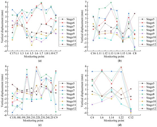
Figure 14.
Vertical displacement of columns and diaphragm walls: (a) Section A; (b) Section B; (c) Section C; (d) Section D.
The above analysis demonstrates that within the first 20 m of excavation depth, soil heave induced by excavation unloading was the dominant deformation factor. As the bracing structure construction was completed, the structural self-weight effect gradually became predominant. Column heave peaked during Stage 8. The maximum heave of 6.9 mm occurred at point L13 in Section B. The maximum differential settlement between adjacent points occurred in Stage 12, reaching 9.33 mm between points L22 and C12, corresponding to a relative differential settlement rate of 0.61‰. The maximum column settlement occurred in Stage 7, with point L19 settling by 44.53 mm. Regarding the displacement distribution pattern, heave deformation exhibited a spatial characteristic of “large in the center, small at the edges”. During Stages 5–6, the vertical displacement profile for each section displayed a “double-peak (M-shaped) distribution”, reflecting the combined effects of unloading in the pit center and bracing constraints at the edges. This evolved into a “single-peak (inverted dome-shaped) distribution” during Stages 7–8, indicating that the overall rebound effect of the base soil strengthened with increasing excavation depth. Upon completion of excavation, the vertical displacement distribution ultimately presented a “large in the center, small at the edges” concave settlement pattern. This was because the diaphragm walls at the pit periphery restricted the settlement of the soil and supporting structures, concentrating the structural settlement primarily within the less constrained central region.
3.4. Pipeline Settlement
Settlement monitoring points P16-P21 are arranged on the north-side power pipeline (1.2 m × 1.1 m); monitoring points P3, P6, P9, P12, and P15 are arranged on the west-side rainwater pipeline (1.8 m × 1.8 m); monitoring points P2, P5, P8, P11, and P14 are arranged on the west-side sewage rectangular ditch (1.8 m × 1.8 m); and monitoring points P1, P4, P7, P10, P13 are arranged on the west-side sewage pipeline (diameter = 0.4 m) to monitor pipeline settlement during foundation pit excavation. The horizontal distance between the north-side power pipeline and the foundation pit is 13.2 m, while the horizontal distances from the west-side rainwater pipeline, sewage rectangular ditch, and sewage pipeline to the foundation pit are 3.2 m, 5.5 m, and 7.3 m, respectively. The distribution of pipeline settlement along the direction parallel to the diaphragm wall under different working conditions is shown in Figure 15. Field analysis revealed that settlement of the west-side stormwater pipeline, wastewater box culvert, and wastewater pipeline increased continuously throughout the excavation process. Settlement of the north-side power pipeline was primarily concentrated in the early stages (Stages 4–8) and was significantly lower overall than that of the west-side pipelines. This difference is attributed to the real-time dynamic axial force compensation provided by the north-side servo steel struts, which effectively suppressed soil displacement outside the pit, thereby reducing pipeline settlement. Regarding settlement distribution morphology, the settlement curves of pipelines parallel to the diaphragm wall exhibited a typical “concave” settlement profile, characterized by smaller settlement near pit corners and larger settlement at the pit center. This reflects the influence of the corner effect. The pit corner regions, constrained by their three-dimensional stress state, exhibit lower soil displacement sensitivity than the two-dimensional stress state prevalent in the pit center [35].
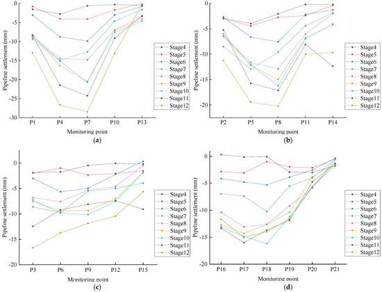
Figure 15.
Pipeline settlement: (a) wastewater pipeline; (b) wastewater box culvert; (c) stormwater pipeline; (d) power pipeline.
Notably, settlement at point P3, located near a pit corner adjacent to the soil export portal, was significantly larger. This anomaly was caused by dynamic loads from frequent vehicle traffic during construction. During the entire excavation process of the foundation pit, the maximum settlements of the sewage pipeline, sewage rectangular ditch, rainwater pipeline, and power pipeline are 28.48 mm, 20.23 mm, 16.68 mm, and 15.06 mm, respectively, all of which do not exceed the warning value required by the project. Comparing settlements of the three parallel pipelines on the west side revealed that the farther wastewater pipeline settled more than the closer stormwater pipeline. This phenomenon is closely related to the shape of the settlement trough. Hsieh [36] posits that maximum ground settlement typically occurs at a distance of approximately 0.5H (where H is excavation depth) from the pit wall. The stormwater pipeline was located at 0.08H, while the wastewater pipeline was at 0.17H. The wastewater pipeline, being closer to the peak of the settlement trough, consequently experienced greater settlement. From the perspective of the dimensionless settlement index, the maximum pipeline settlement in the west-side ordinary segment is 0.67‰H, while that in the north-side servo segment is only 0.36‰H, with the latter being 46% lower than the former. This quantitatively verifies the efficient control capability of servo steel struts on the settlement of surrounding pipelines.
3.5. Horizontal and Vertical Displacement for the Metro Tunnels
Figure 16 presents the monitoring results of horizontal and vertical displacement for the metro tunnels during both the construction and suspension periods of the foundation pit. Negative horizontal displacement values indicate movement towards the excavation interior, while positive values indicate movement away from it. Negative vertical values represent settlement, and positive values represent heave. Given the significant construction impact on the up-track tunnels of Line 11 and Line 9 due to their proximity to the pit and the relatively minor deformation observed on the more distant down-track tunnels of Line 11 and Line 9, the analysis focused on the deformation characteristics of the up-track tunnels. At the completion of excavation, the maximum horizontal displacements are −5.1 mm at Section 22 of Line 11 Up Line and −5.4 mm at Section 23 of Line 9 Up Line, respectively; the maximum vertical displacements are −5.4 mm at Section 27 of Line 11 Up Line and −5.4 mm at Section 33 of Line 9 Up Line, respectively. All monitored values were less than the project’s control standard of 10 mm [37]. This demonstrates that the servo steel strut system effectively mitigated the deformation impact of the ultra-deep foundation pit on the adjacent metro tunnels. Simultaneously, the barrier effect of the isolation piles adopted for the pit [38] also contributed to restricting tunnel deformation. These combined measures ensured tunnel deformation remained within safe thresholds.
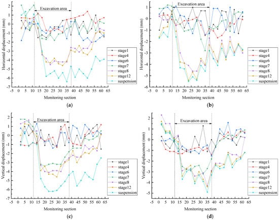
Figure 16.
Displacement of metro tunnels: (a) horizontal displacement of line 11 up track; (b) horizontal displacement of line 9 up track; (c) vertical displacement of line 11 up track; (d) vertical displacement of line 9 up track.
Analysis of deformation during the construction suspension period revealed a cumulative increasing trend in displacement for both the Line 11 Up Line and Line 9 Up Line. This phenomenon stems from the rheological properties of the artificial fill and soft soil in the reclaimed area, where the soil undergoes continuous creep deformation under sustained stress, consequently inducing increased tunnel deformation. The deformation increase was more pronounced for the Line 11 Up Line, primarily because its closer proximity to the excavation subjected it to a stronger additional stress field induced by the excavation unloading, thereby amplifying the effect of soil creep on the tunnel.
Regarding deformation distribution patterns, both the horizontal and vertical displacement curves of the metro tunnels exhibited typical normal distribution characteristics. Tunnels near the pit center experienced larger deformation due to the two-dimensional (2D) stress state prevalent there. Conversely, tunnels in the corner regions, influenced by a 3D stress state, exhibited significantly reduced deformation. Notably, tunnel deformation in sections 1–10 at the northwest corner was smaller than that in sections 40–60 at the northeast corner. The main reason is that the northwest corner is adjacent to the main structure of the metro station, whose large structural stiffness restricts tunnel displacement, whereas the northeast corner is affected by the superposition effect of excavation of the adjacent foundation pit to the east, leading to increased tunnel deformation. Further analysis of the corner effect’s influence range revealed that tunnel sections within 10 m of a pit corner experienced smaller deformation compared to the pit center, highlighting a significant corner constraint effect. When the distance from a pit corner exceeded 10 m, the tunnel deformation characteristics gradually approached those of plane strain conditions.
4. Discussion
4.1. Phased Analysis of Metro Tunnel Deformation
Based on the analysis in Section 3.5, the metro tunnel near the pit center was less affected by the corner effect. Therefore, the average deformation values from sections 21–29 adjacent to the pit center were selected to represent the tunnel deformation at each construction stage. This approach was used to systematically study the deformation characteristics of the metro tunnel over the entire construction cycle, from the construction of the retaining structure to the suspension period after excavation. The monitoring data spanned from 11 May 2018, to 12 March 2023. The cumulative deformation of the metro tunnel throughout the entire construction process and the percentage contribution of incremental deformation per stage are analyzed, with results shown in Figure 17. Figure 17 reveals that the excavation stages contributed significantly to tunnel deformation, accounting for 62–89% of the total deformation. Among them, horizontal displacement is more significantly affected by Stage 8, while vertical displacement responds more strongly to Stage 7. The impact of excavation on the metro tunnel is most pronounced when the excavation face approaches the tunnel’s buried depth, as the difference between these depths becomes minimal. During Stages 9–10, the tunnel deformation shows a slight recovery. The maximum reduction in horizontal and vertical displacements of Line 11 is 0.09 mm and 0.11 mm, respectively; for Line 9, the maximum reduction in horizontal displacement is 0.17 mm, and the reduction in vertical displacement is 0.03 mm.
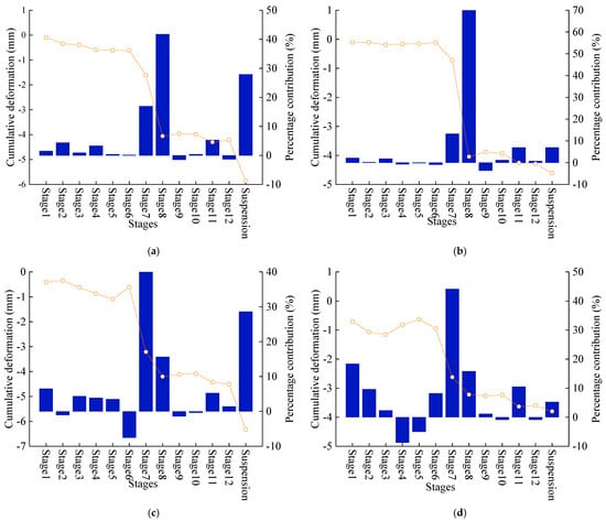
Figure 17.
Proportion of displacement of metro tunnels in each construction stage: (a) horizontal displacement of line 11 up track; (b) horizontal displacement of line 9 up track; (c) vertical displacement of line 11 up track; (d) vertical displacement of line 9 up track.
This rebound is attributed to the active axial force compensation mechanism of the servo steel struts. By dynamically adjusting the strut load, the deformation of the diaphragm wall was partially reduced, causing soil movement away from the pit. This altered the additional stress state induced by excavation unloading on the metro tunnel, thereby controlling its deformation. The deformation increment during stage 11 accounts for 5% to 11% of the total deformation. The reason lies in the use of reinforced concrete supports at this stage, which, as previously analyzed, exhibit weaker deformation control effectiveness compared to servo steel struts. Consequently, the tunnel deformation induced by excavation is relatively larger during this phase.
Monitoring data from the construction suspension period further reveals significant time-dependent effects of the foundation pit in the reclaimed area: For the adjacent Up Line of Line 11, the increments of horizontal and vertical displacement during the suspension period accounted for 28% and 29% of the total deformation, respectively, with deformation rates reaching 0.085 mm/month and 0.095 mm/month. In contrast, for the more distant Up Line of Line 9, the deformation during the suspension period constituted only 7% and 5% of the total, with deformation rates dropping to 0.017 mm/month and 0.011 mm/month. This difference, exceeding fivefold, indicates that tunnels closer to the foundation pit experience more pronounced time-dependent effects.
Analyzing from the perspective of stratum characteristics, the project site is located in a soft soil area where the rheological properties of soft soils are significant [39]. Simultaneously, as the artificial fill layer formed by reclamation has not undergone sufficient time for compaction and consolidation, the reclaimed strata are looser and more prone to settlement than natural soil layers [40]. Consequently, the substantial presence of artificial fill and soft soil at the site makes the time-dependent effects of the foundation pit in the reclaimed area more significant. Furthermore, research by Yu et al. [26] also confirms that factors such as soil moisture content, dry density, cation exchange capacity, and particle arrangement influence the rheological properties of reclaimed soil. Under the combined effects of soil self-weight and external loads, the particles of reclaimed soil gradually rearrange, and pore water is slowly expelled, leading to the manifestation of rheological behavior in reclaimed soil. During the suspension phase of the excavation, the cumulative effect of time causes the rheological properties of the reclaimed soil to result in continuously increasing deformation of the metro tunnel over time, which is a key reason for the disproportionately high contribution of tunnel deformation during the suspension phase.
From a safety control perspective, the maximum tunnel deformations throughout the entire construction process met code requirements. The maximum horizontal and vertical deformations of the Up Line of Line 11 were 7.0 mm and 7.8 mm, respectively, while those for the Up Line of Line 9 were 5.4 mm and 5.5 mm, respectively. All values were below the 10 mm limit stipulated by the Shenzhen Metro Group [37]. This verifies the effectiveness of this project’s deformation control measures in managing long-term deformation.
The retaining structure construction stage has limited impact on tunnel deformation; the proportions of horizontal and vertical displacements of the Up Line of Line 11 are 1.5% and 6.5%, respectively, and those of the Up Line of Line 9 are 2.1% and 18.4%, indicating that retaining system construction primarily induced tunnel settlement, with minimal effect on horizontal displacement. During the stages of retaining structure construction, grouting, and engineering pile construction before excavation, the cumulative tunnel deformation remained below 1 mm. This demonstrates the effectiveness of measures like isolation piles and jet-grouted piles in mitigating disturbance from early-stage construction activities. The barrier effect of the isolation piles significantly reduced the lateral stress release in the trench walls during diaphragm wall panel excavation and minimized soil structure disturbance caused by machinery. Jet-grouted piles achieved pre-reinforcement of the soil surrounding the trench walls through high-pressure injection of cement slurry. This enhanced soil compactness and shear strength, thereby reducing the degree of soil structure damage during trenching and effectively controlling tunnel deformation.
To control the deformation impact of foundation pit construction on adjacent metro tunnels, the following comprehensive measures are recommended. First, during the excavation phase, the construction process should be optimized, particularly when approaching the tunnel burial depth. Block-by-block excavation should be adopted, and servo steel struts capable of actively compensating axial forces should be prioritized to suppress instantaneous deformation. Second, to address the time-dependent effects during the suspension phase, the suspension phase should be minimized. After the foundation pit is completed, the base slab and lower structure should be constructed in a timely manner. During the suspension phase, automated monitoring should be enhanced so that compensatory measures can be taken promptly if continuous deformation occurs due to the rheological properties of soft soil in reclaimed areas. Additionally, during the retaining structure construction stage, barrier measures such as isolation piles and jet grouting piles should be employed to isolate construction-induced disturbances. Finally, dynamic monitoring throughout the entire construction process should be implemented, with priority given to the servo steel strut system to ensure the long-term safety of the tunnel.
4.2. Displacement Relationship Between the Metro Tunnel and Diaphragm Wall
To clarify the correlation between the horizontal displacement of diaphragm walls and the deformation of metro tunnels, thereby providing theoretical support and technical guidance for engineering practice, this paper proposes a prediction model for the deformation envelope curve of metro tunnels. The envelope curve model consists of an average line and upper and lower envelope lines, which are used to establish the relationship between the horizontal displacement of diaphragm walls and metro tunnel deformation, as well as the data envelope interval, through fitting analysis. In practical engineering, the envelope curve model can be employed to approximately predict the deformation of metro tunnels caused by excavation and the range within which the tunnel deformation falls. Statistical analysis was conducted on the horizontal displacement of diaphragm walls at sections S1–S5 on the north side of the excavation pit and the deformation data from corresponding monitoring sections of the adjacent metro tunnel. The analysis focused solely on tunnel deformation during the excavation stage, excluding the influence of construction processes prior to excavation. Figure 18 shows the scatter distribution of the maximum horizontal displacement of the diaphragm wall and the deformation of the corresponding tunnel monitoring section at each excavation stage, revealing a significant linear correlation between the two. Based on least squares fitting, the coefficient of determination of the monitoring data ranges from 0.817 to 0.900, indicating a strong correlation between the horizontal displacement of the diaphragm wall and the deformation of the metro tunnel. Table 3 further defines the upper and lower boundaries of this linear relationship, providing clear limits for deformation prediction.
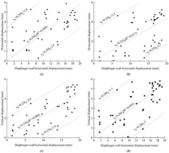
Figure 18.
Displacement relationship between the metro tunnels and diaphragm walls: (a) horizontal displacement of line 11 up track; (b) horizontal displacement of line 9 up track; (c) vertical displacement of line 11 up track; (d) vertical displacement of line 9 up track.

Table 3.
Measurement data distribution range.
Chen et al. [41] conducted a case study on deep foundation pit excavation in soft soil areas at metro tunnel intersections, demonstrating a significant linear relationship between the horizontal displacement of diaphragm walls supported by reinforced concrete struts and the horizontal and vertical displacements of adjacent metro tunnels. This study further reveals that similar patterns exist when servo steel struts are applied. The distribution of monitoring data in the figure shows a relatively wide range, reflecting a certain degree of uncertainty in the linear relationship. This dispersion is primarily attributed to three reasons: first, the artificial fill layer at the site exhibits poor uniformity and certain anisotropy in soil physical and mechanical properties; second, the axial force compensation response time of the servo support system is delayed, affecting the real-time control of deformation; third, dynamic loads such as vehicles during construction generate additional displacements, interfering with monitoring data. In summary, although there is some uncertainty in the linear relationship between the horizontal displacement of the diaphragm wall and tunnel deformation, Figure 18 shows that the monitoring data overall fall within a specific range. For similar ultra-deep excavation projects in reclaimed areas, the envelope curve prediction model proposed in this paper can be used to approximate the horizontal and vertical displacements of metro tunnels induced by excavation. This prediction model not only provides data support for optimizing support schemes during the preliminary engineering stage but also serves as a practical pre-assessment tool for tunnel deformation warnings during construction, thereby offering key technical support for ensuring the safety of excavation and adjacent metro tunnels.
5. Conclusions
This study, by focusing on an ultra-deep foundation pit project in Shenzhen’s reclaimed area, reveals the deformation characteristics of ultra-deep foundation pits in reclaimed strata and the efficacy of key measures like servo steel struts through full-cycle field monitoring and analysis. The main conclusions are as follows:
- The protective trenching effect of the isolation piles and jet-grouted piles significantly reduced soil disturbance during diaphragm wall trenching. This resulted in low levels of surrounding ground settlement and metro tunnel settlement induced during the retaining structure construction phase, with minimal impact on tunnel horizontal displacement. The deformation increment of adjacent metro tunnels caused by Stages 7–8 (excavation depth approximately 10–20 m) was the most significant in adjacent metro tunnels. Excavation caused tunnel heave when the depth was less than the tunnel’s buried depth. The incremental deformation peaked when the excavation depth approached the tunnel’s buried depth, and its rate of increase significantly diminished beyond 20 m.
- Field measurements from this project demonstrate the superior performance of servo steel struts over conventional struts in controlling ultra-deep foundation pit deformation. Due to their active axial force compensation mechanism, the maximum horizontal displacement of the diaphragm wall in the servo steel strut section was 24% less than in the conventional section. Ground surface settlement was reduced by 29%, pipeline settlement by 46%, and the maximum metro tunnel deformation was limited to 5.4 mm, well within the stringent 10 mm safety threshold. The distinct “inflection” characteristic of the servo-side diaphragm wall, contrasting with the “smooth” curve on the conventional side, reflects the local displacement-restoring effect of active support. A slight rebound in metro tunnel deformation occurred during Stages 9–10 due to the servo steel struts compensation mechanism.
- The significant rheological properties of artificial fill and soft soil in reclaimed areas result in notable time-dependent effects on foundation pit deformation. During the construction suspension period, metro tunnel deformation accounted for up to 29% of the total displacement, with tunnels closer to the foundation pit exhibiting more pronounced time-dependent effects. Therefore, timely support after excavation is crucial to reduce unsupported exposure time. Following excavation completion, the base slab should be poured and the substructure constructed in a timely manner to mitigate the amplification of time-dependent effects caused by prolonged construction activities. The corner effect of the foundation pit is significant, with surface settlement, pipeline settlement, and metro tunnel deformation near the corner being substantially smaller than those near the mid-span section. Beyond 10 m from the corner, tunnel deformation characteristics gradually approach a plane strain state.
- This paper proposes a deformation envelope prediction model for metro tunnels in ultra-deep foundation pits in reclaimed areas. The fitting analysis results indicate strong linear relationships between both the horizontal and vertical displacements of the metro tunnel and the horizontal displacement of the diaphragm wall, with monitoring data generally distributed within a specific range. Based on this pattern, the upper and lower bounds of the linear relationship envelope are further defined, establishing clear boundaries for tunnel deformation prediction. For similar ultra-deep foundation pit projects in reclaimed areas, the proposed envelope prediction formula can be used to preliminarily quantify the impact of excavation on adjacent metro tunnel deformation. This provides a practical pre-assessment basis and technical support for optimizing support schemes during the early project stages and early warning of tunnel deformation during construction.
- This research validated the applicability of servo steel struts in ultra-deep foundation pits within reclaimed areas. By optimizing the original design through the application of servo steel struts, the project effectively shortened the construction schedule and reduced costs while demonstrating superior deformation control capabilities for the retaining structure, surrounding pipelines, and metro tunnels. In addition to the application of servo steel struts, comprehensive measures such as bottom-sealed diaphragm walls, isolation piles, grouting curtains, and timely support after excavation can be used to reduce the adverse impact on the surrounding environment during foundation pit construction and ensure the smooth implementation of ultra-deep foundation pit projects in reclaimed areas.
While this study systematically reveals the deformation behavior of ultra-deep foundation pits in reclaimed areas and the control effectiveness of measures such as servo steel struts, it has notable limitations. The analysis was conducted based solely on the actual construction sequence, without considering the impact of different construction sequences or varying intervals between construction stages. The synergistic effects of combined measures—such as bottom-sealed diaphragm walls, isolation piles, and servo steel struts—were not quantitatively evaluated. Moreover, the rheological properties of the reclaimed soil were inferred indirectly from field monitoring data of the foundation pit and tunnels, without conducting rheological tests or in-depth investigation into the mechanism of time-dependent effects based on experimental results. Future research should focus on the following directions: comparing deformation differences under various construction sequences through numerical simulations and field validation; quantifying the synergistic effects of multiple measures using orthogonal experimental design; investigating the relationship between construction stage intervals and deformation by designing multi-interval working conditions; performing consolidation and creep tests on reclaimed soil to obtain rheological parameters; deepening the study of time-dependent mechanisms by integrating experimental results; and optimizing the tunnel deformation prediction model while validating it with additional case studies. These efforts will provide more comprehensive support for the design and construction of ultra-deep foundation pits in reclaimed areas.
Author Contributions
Conceptualization, J.C., Y.L. and Z.W.; methodology, Y.L.; software, J.C. and B.P.; validation, J.C. and Y.H.; formal analysis, B.P. and Y.H.; investigation, Y.L., Z.W. and B.P.; resources, B.P.; data curation, Z.W.; writing—original draft preparation, J.C.; writing—review and editing, Y.L. and Y.H.; visualization, J.C.; supervision, Y.L. and Y.H.; project administration, Y.L.; funding acquisition, Y.L. All authors have read and agreed to the published version of the manuscript.
Funding
This research was funded by the National Natural Science Foundation of China (U2340230) and the National Natural Science Foundation of China (U1711266).
Data Availability Statement
The data presented in this study are available on request from the corresponding author. The data are not publicly available due to their containing information that could compromise the privacy of research participants.
Acknowledgments
Thank you Juan Kong for your data and project support.
Conflicts of Interest
Author Ze Wu and Bin Peng were employed by the company China Railway Engineering Consulting Group Co., Ltd. The remaining authors declare that the research was conducted in the absence of any commercial or financial relationships that could be construed as a potential conflict of interest.
References
- Xu, B.; Feng, G.; Li, Z.; Wang, Q.; Wang, C.; Xie, R. Coastal subsidence monitoring associated with land reclamation using the point target based SBAS-InSAR method: A case study of Shenzhen, China. Remote Sens. 2016, 8, 652. [Google Scholar] [CrossRef]
- He, Y.; Xu, G.; Kaufmann, H.; Wang, J.; Ma, H.; Liu, T. Integration of InSAR and LiDAR Technologies for a Detailed Urban Subsidence and Hazard Assessment in Shenzhen, China. Remote Sens. 2021, 13, 2366. [Google Scholar] [CrossRef]
- Sharma, J.; Hefny, A.; Zhao, J.; Chan, C. Effect of large excavation on deformation of adjacent MRT tunnels. Tunn. Undergr. Space Technol. 2001, 16, 109–117. [Google Scholar] [CrossRef]
- Tan, Y.; Lu, Y. Responses of shallowly buried pipelines to adjacent deep excavations in Shanghai soft ground. J. Pipeline Syst. Eng. Pract. 2018, 9, 05018002. [Google Scholar] [CrossRef]
- Bovolenta, R.; Brencich, A. Effect of deep excavations and deformable retaining structures on neighboring buildings: A case study. Eng. Fail. Anal. 2021, 128, 105269. [Google Scholar] [CrossRef]
- Song, D.; Chen, Z.; Dong, L.; Tang, G.; Zhang, K.; Wang, H. Monitoring analysis of influence of extra-large complex deep foundation pit on adjacent environment: A case study of Zhengzhou City, China. Geomat. Nat. Hazards Risk 2020, 11, 2036–2057. [Google Scholar] [CrossRef]
- Chen, Y.; Jia, P.J.; Ji, X.B. Investigation into the performance of a covered top-down pit-in-pit deep excavation in Shenzhen soil-rock mixed strata. Arab. J. Sci. Eng. 2021, 46, 10419–10437. [Google Scholar] [CrossRef]
- Liang, R.; Wu, J.; Sun, L.; Shen, W.; Wu, W. Performances of adjacent metro structures due to zoned excavation of a large-scale basement in soft ground. Tunn. Undergr. Space Technol. 2021, 117, 104123. [Google Scholar] [CrossRef]
- Peng, T.; Ren, D.; Kang, C.; Liu, H.; Xue, P.; Huang, H. Deformation characteristics of soft soil induced by deep excavation and its impact on adjacent tunnels: A case study in Shanghai. KSCE J. Civ. Eng. 2024, 28, 1715–1728. [Google Scholar] [CrossRef]
- Wang, C.; Liang, R.; Wu, J.; Li, Z.; Ding, Z.; Wu, W. Performances of shield-driven tunnels subjected to excavation of a large-scale basement in soft soils. Int. J. Geomech. 2024, 24, 05023014. [Google Scholar] [CrossRef]
- Ni, X.; Lu, J.; Wang, Y.; Shi, J.; Chen, W.; Tang, L. Field investigation of the influence of dewatering and basement excavation on ground and structure responses. Tunn. Undergr. Space Technol. 2021, 117, 104121. [Google Scholar] [CrossRef]
- Nicotera, M.V.; Russo, G. Monitoring a deep excavation in pyroclastic soil and soft rock. Tunn. Undergr. Space Technol. 2021, 117, 104130. [Google Scholar] [CrossRef]
- Li, M.G.; Demeijer, O.; Chen, J.J. Effectiveness of servo struts in controlling excavation-induced wall deflection and ground settlement. Acta Geotech. 2020, 15, 2575–2590. [Google Scholar] [CrossRef]
- Nangulama, H.K.; Zhou, J. Deformation control monitoring of basement excavation at field construction site: A case of hydraulic servo steel enhancement geotechnology. Adv. Civ. Eng. 2022, 2022, 6234581. [Google Scholar] [CrossRef]
- Zhao, P.; Qiu, Y.; Liu, F.; Wang, Z.; Guo, P. Investigation on performance of steel strut servo system braced deep excavation adjacent to existing buildings: A case study. Sci. Rep. 2025, 15, 37550. [Google Scholar] [CrossRef]
- Di, H.; Jin, Y.; Zhou, S.; Wu, D. A hybrid method to determine optimal design axial forces of servo steel struts in excavations with high deformation requirements. Eng. Comput. 2023, 40, 997–1015. [Google Scholar] [CrossRef]
- Li, M.-G.; Xiao, Q.-Z.; Liu, N.-W.; Chen, J.-J. Predicting wall deflections for deep excavations with servo struts in soft clay. J. Geotech. Geoenviron. Eng. 2024, 150, 04024001. [Google Scholar] [CrossRef]
- Hu, H.; Hu, X.; Gong, X. Predicting the strut forces of the steel supporting structure of deep excavation considering various factors by machine learning methods. Undergr. Space 2024, 18, 114–129. [Google Scholar] [CrossRef]
- Chen, B.; Yan, T.; Song, D.; Luo, R.; Zhang, G. Experimental investigations on a deep excavation support system with adjustable strut length. Tunn. Undergr. Space Technol. 2021, 115, 104046. [Google Scholar] [CrossRef]
- Di, H.; Jin, Y.; Zhou, S.; Zhang, X.; Wu, D.; Guo, H. Experimental study on the adjustments of servo steel struts in deep excavations. Acta Geotech. 2023, 18, 6615–6629. [Google Scholar] [CrossRef]
- Di, H.; Guo, H.; Zhou, S.; Chen, J.; Wen, L. Investigation of the axial force compensation and deformation control effect of servo steel struts in a deep foundation pit excavation in soft clay. Adv. Civ. Eng. 2019, 2019, 5476354. [Google Scholar] [CrossRef]
- Li, H.; Tang, Y.; Liao, S.; Shen, M. Structural response and preservation of historic buildings adjacent to oversized deep excavation. J. Perform. Constr. Facil. 2021, 35, 04021095. [Google Scholar] [CrossRef]
- Nangulama, H.K.; Jian, Z.; Xiao, Z.; Zhu, J.-C.; Yuan, F.-F. Stage-by-stage control effect field analysis of steel material servo enhanced support system on lateral displacement and bending moment during deep basement excavation. Case Stud. Constr. Mater. 2022, 16, e01068. [Google Scholar] [CrossRef]
- Plant, G.W.; Covil, C.S.; Hughes, R.A. Site Preparation for the New Hong Kong International Airport—The Design, Construction and Performance of the Airport Platform; Thomas Telford: London, UK, 1998. [Google Scholar]
- Jiang, L.; Lin, H. Integrated analysis of SAR interferometric and geological data for investigating long-term reclamation settlement of Chek Lap Kok Airport, Hong Kong. Eng. Geol. 2010, 110, 77–92. [Google Scholar] [CrossRef]
- Yu, Q.; Wang, Q.; Yan, X.; Yang, T.; Song, S.; Yao, M.; Zhou, K.; Huang, X. Ground deformation of the Chongming East Shoal Reclamation Area in Shanghai based on SBAS-InSAR and laboratory tests. Remote Sens. 2020, 12, 1016. [Google Scholar] [CrossRef]
- Li, D.; Li, B.; Zhang, Y.; Fan, C.; Xu, H.; Hou, X. Spatial and temporal characteristics analysis for land subsidence in Shanghai coastal reclamation area using PS-InSAR method. Front. Mar. Sci. 2022, 9, 1000523. [Google Scholar] [CrossRef]
- Park, K.; Kim, Y.J.; Chen, J.; Nam, B.H. InSAR-based investigation of ground subsidence due to excavation: A case study of Incheon City, South Korea. Int. J. Geo-Eng. 2024, 15, 26. [Google Scholar] [CrossRef]
- Ma, F.; Li, S.; Wang, Q. Study on the impact of deep foundation excavation of reclaimed land on the deformation of adjacent subway tunnels. Buildings 2024, 14, 1771. [Google Scholar] [CrossRef]
- Shenzhen Municipal Government. Shenzhen Sustainable Development Plan (2017–2030); Shenzhen Municipal Government: Shenzhen, China, 2017.
- Wang, S.; Xu, L.; Zhang, X.; Long, L.; Zhuang, X. Development and Field Analysis of a Novel Servo Concrete Bracing System for Deep Foundation Pit Excavation. Buildings 2024, 14, 1674. [Google Scholar] [CrossRef]
- Zuo, R.Y.; Huang, T.H. Practice and Discussion on Deformation Control Design of Deep Foundation Pits for Buildings in Shenzhen. In Proceedings of the 2018 West Lake Forum on Geotechnical Engineering, Hangzhou, China, 27 October 2018; pp. 220–239. [Google Scholar]
- Roboski, J.; Finno, R.J. Distributions of ground movements parallel to deep excavations in clay. Can. Geotech. J. 2006, 43, 43–58. [Google Scholar] [CrossRef]
- Moormann, C. Analysis of Wall and Ground Movements Due to Deep Excavations in Soft Soil Based on a New Worldwide Database. Soils Found. 2004, 44, 87–98. [Google Scholar] [CrossRef]
- Finno, R.J.; Blackburn, J.T.; Roboski, J.F. Three-dimensional effects for supported excavations in clay. J. Geotech. Geoenviron. Eng. 2007, 133, 30–36. [Google Scholar] [CrossRef]
- Hsieh, P.G.; Ou, C.Y. Shape of ground surface settlement profiles caused by excavation. Can. Geotech. J. 1998, 35, 1004–1017. [Google Scholar] [CrossRef]
- Shenzhen Metro Group Co., Ltd. Measures for the Management of Works in Metro Operation Safety Protection Zones and Construction Planning Control Zones (2018 Edition); Shenzhen Metro Group Co., Ltd.: Shenzhen, China, 2018. [Google Scholar]
- Liu, K.; Xu, X.B.; Hu, Q.; Bin Zeng, L.; Wang, J.C. 1 g Model Test on the Use of Isolation Piles for Tunnel Protection Adjacent to Soft Soil Excavation. Transp. Geotech. 2022, 35, 100790. [Google Scholar] [CrossRef]
- Harahap, S.E.; Ou, C.Y. Finite element analysis of time-dependent behavior in deep excavations. Comput. Geotech. 2020, 119, 103300. [Google Scholar] [CrossRef]
- Zhou, L.; Liu, S.; Li, J.; Pan, Y.; Wang, C.; Huang, L.; Huang, L. Investigating surface deformation and its intrinsic mechanism in Shenzhen, China using Sentinel-1A SAR imagery. Earth Space Sci. 2023, 10, e2023EA002905. [Google Scholar] [CrossRef]
- Chen, G.; Zhang, X.H.; Zhang, S.J.; Huang, F.; Xiao, H.; Ma, H.Z.; Luo, L.N.; Bao, H. Response Monitoring and Analysis in Deep Foundation Pit Excavation: A Case Study in Soft Soil at Subway Tunnel Intersections. Buildings 2023, 13, 1286. [Google Scholar] [CrossRef]
Disclaimer/Publisher’s Note: The statements, opinions and data contained in all publications are solely those of the individual author(s) and contributor(s) and not of MDPI and/or the editor(s). MDPI and/or the editor(s) disclaim responsibility for any injury to people or property resulting from any ideas, methods, instructions or products referred to in the content. |
© 2025 by the authors. Licensee MDPI, Basel, Switzerland. This article is an open access article distributed under the terms and conditions of the Creative Commons Attribution (CC BY) license (https://creativecommons.org/licenses/by/4.0/).