Abstract
This study investigates the feasibility of using scrap aerogel (SAG) generated during silica aerogel production as a partial substitute for sand in 3D concrete printing. Through comprehensive experiments and finite element analysis, the printability, thermal insulation properties, and mechanical characteristics (compressive strength and flexural strength) of 3D-printed scrap-aerogel-incorporated concrete (3DP-SAIC) were evaluated at different SAG replacement ratios. The results indicate that the thermal conductivity of the concrete decreases with increasing SAG content. When 30% of the sand is replaced by aerogel, the thermal conductivity perpendicular to the printed layer direction is reduced by 40.90%. The thermal properties of SAIC closely resemble those of aerogel concrete (AIC) while significantly reducing manufacturing costs. Compared to existing 3D-printed aerogel concrete, this study achieves a 73.1% cost reduction. Compared to standard cast specimens (SC-SAIC), 3DP-SAIC exhibits pronounced anisotropic thermal behavior. The study also evaluated the reinforcement effects of four basalt fibers (BF) with different aspect ratios on the mechanical properties of 3DP-SAIC. Although BF provides limited enhancement to compressive strength, it significantly boosts flexural strength. Specifically, BF with a length of 12 mm and a diameter of 17 μm increases flexural strength by 26.97%. These findings highlight the application potential of recycled aerogel in 3D-printed concrete, offering a sustainable thermal insulation solution with suitable mechanical properties for green building technologies.
1. Introduction
As global climate change intensifies, the urgency to reduce carbon emissions from the building sector has reached a critical juncture [1,2,3]. Buildings are significant contributors to carbon emissions, with their emissions originating primarily from three key stages: the production and transportation of building materials, the construction process, and the operation and maintenance phase [4]. Therefore, transforming building construction processes and enhancing the insulation performance of building envelopes are essential strategies for mitigating the carbon footprint of buildings [5,6].
Three-dimensional concrete printing is rapidly gaining traction as a pioneering construction technology, distinguished by its remarkable efficiency, unparalleled design flexibility, and strong commitment to sustainability [7]. Traditional construction methods often lead to substantial material waste, as raw materials are typically cut to size and assembled on-site [8]. In stark contrast, 3D printing technology minimizes waste by precisely fabricating building components using only the exact amount of material required. Moreover, 3D printing opens the door to a wide range of sustainably sourced green building materials. For instance, recycled rubber [9,10], glass [11,12,13], concrete [14,15,16], plastics and biodegradable materials can be employed, thereby reducing reliance on traditional cement—an energy-intensive material that contributes significantly to carbon emissions [17]. As a result, 3D printing technology is not only revolutionizing the construction industry but also propelling green building practices forward, with a clear trend towards sustainable growth [18].
Thermal insulation is a critical factor in assessing the performance of building materials, especially under extreme climatic conditions. It is essential for improving building energy efficiency and maintaining indoor comfort [19]. For concrete, a cornerstone material in construction, its thermal conductivity and stability significantly impact its role in the building envelope. In recent years, to enhance the thermal insulation performance of building materials, researchers have actively explored integrating new low-thermal-conductivity materials with traditional concrete [20]. Among these innovative materials, SiO2 aerogels have garnered significant attention. These highly nanoporous materials exhibit exceptional properties, including a remarkably low thermal conductivity of 0.013 W/(m·K) at room temperature, outstanding insulating capabilities, and excellent fire-resistant safety features [21,22,23]. Studies have consistently shown that incorporating aerogels into concrete can substantially reduce its thermal conductivity [24,25,26,27]. For example, Gao et al. [28] developed aerogel-incorporated concrete (AIC) by embedding SiO2 aerogel particles into the concrete matrix. This innovation resulted in a dramatic reduction in thermal conductivity, from 1.86 W/(m·K) to 0.26 W/(m·K). Similarly, Khamidi et al. [29] demonstrated that adding SiO2 aerogel as a filler in cement paste significantly lowered its thermal conductivity. Fickler et al. [30] further advanced this concept by developing high-performance aerogel concrete, which combined the excellent thermal insulation properties of aerogels with the high compressive strength of conventional concrete. Tsioulou et al. [31] achieved a 31% reduction in thermal conductivity by incorporating 30 vol% of aerogel into the concrete mixture. These findings underscore the transformative potential of SiO2 aerogels in enhancing the thermal performance of concrete, paving the way for more energy-efficient and sustainable building materials.
Furthermore, Ma et al. [32] discovered that integrating SiO2 aerogel into 3D-printed concrete can significantly enhance its thermal insulation performance. However, this integration also notably diminishes the mechanical properties of 3D-printed concrete, which is a critical concern. Mechanical properties are fundamental indicators for assessing the load-bearing capacity and safety of construction materials. To address the issue of compromised mechanical strength in 3D-printed concrete, researchers have explored various strategies, such as incorporating nanomaterials or fibers to bolster the concrete’s performance [33,34,35]. Among these solutions, basalt fibers (BF) have emerged as a promising material for 3DCP applications, thanks to their exceptional resistance to corrosion, abrasion, and heat [36,37]. Studies have shown that adding an appropriate amount of basalt fibers to 3D-printed concrete can substantially improve both the printability and mechanical properties of the concrete [38]. For instance, Hambach and Volkmer [39] found that the inclusion of basalt fibers significantly increased the flexural strength of 3D-printed concrete. Li et al. [40] experimented with different volume ratios of basalt fibers in 3D-printed concrete and determined that a basalt fiber volume ratio of 7.5‰ yielded the highest compressive and flexural strength. Similarly, Ma et al. [37] demonstrated that incorporating basalt fibers at a volume ratio of 5‰ resulted in optimal printability and mechanical properties for 3D-printed concrete. These findings highlight the potential of combining SiO2 aerogels and basalt fibers to achieve a balance between thermal insulation and mechanical performance in 3D Construction Printing, thereby advancing the technology towards more sustainable and durable construction solutions.
Aerogel materials, when combined with 3D-printed concrete technology, offer significant potential for developing energy-efficient buildings. Their ability to enhance thermal insulation makes them a highly promising solution for sustainable construction. However, the current industrial production of SiO2 aerogels, which relies on high-pressure supercritical drying technology, results in a production cost that is more than ten times higher than that of traditional insulation materials [41]. As a result, aerogels are currently limited to specialized applications such as aerospace, new energy vehicle batteries, and oil pipelines. This high cost remains a key barrier to the widespread adoption of aerogels in the building sector. Additionally, as the large-scale production of aerogels increases, the volume of aerogel solid waste has also risen dramatically. The disposal of this waste poses significant challenges. Given the low calorific value of aerogel combustion, landfilling is currently the primary method of waste disposal. However, this approach can lead to ecological problems, further complicating the sustainability of aerogel use in construction. Zhu [42] mixed scrap aerogel (SAG) with glazed hollow beads (GHB) to create a composite insulating aggregate for preparing scrap-aerogel insulating mortar (SAIM). Results demonstrated that SAIM exhibits excellent thermal insulation properties, the cost of SAIM has been reduced by about 85% compared to the cost of conventional aerogel insulation mortar (AIM).
A literature review indicates that no studies have yet reported on combining scrap-aerogel concrete with 3D-printed concrete technology. Three-dimensionally-printed cementitious materials require high workability to ensure successful extrusion and maintain desired properties. However, hydrophobic scrap aerogel theoretically reduces the flowability and water retention of cementitious materials [43]. Therefore, this study aims to investigate the feasibility of incorporating scrap aerogel at different contents into 3D-printed concrete (3DCP), evaluate the anisotropic thermal and mechanical properties of scrap-aerogel-containing concrete suitable for 3D printing in both fresh and hardened states, and systematically assess the reinforcement effect of basalt fibers (BF) of varying lengths and diameters on the mechanical properties of the concrete.
2. Materials and Methods
2.1. Raw Material and Mix Proportions
2.1.1. Material
The cementitious materials for the 3DCP studied in this experiment include Ordinary Portland Cement (OPC 42.5, supplied by Yangchun Cement Co., Ltd., Weifang, China), silica fume (provided by Henan Yuanheng Environmental Protection Engineering Co., Zhengzhou, China), and fly ash (obtained from Zhengzhou Yuzhong Power Plant Fly Ash Development Co., Zhengzhou, China). Silica fume is known for its effectiveness in preventing segregation and water bleeding during the pumping process, while significantly reducing the pumping resistance of the concrete mixture. The incorporation of fly ash in 3D-printed concrete accelerates the hydration reaction and contributes to improved mechanical strength. A polycarboxylic acid-based high-efficiency water-reducing agent (supplied by Zhucheng City Jiuqi Building Materials Co., Ltd., Weifang, China) was also employed, which effectively reduces the water-to-cement ratio, enhances concrete strength, and ensures the required fluidity for the 3D printing process. The chemical compositions of the cement, silica fume, and fly ash are presented in Table 1.

Table 1.
Chemical composition of cement, silica fume and fly ash.
Before the start of the printing test, hydrophobic scrap silica aerogel (SAG) requires pre-grinding. The composite aggregate consists of sand and pre-treated hydrophobic SAG, and the cumulative particle size distribution of both materials is presented in Figure 1. The scrap hydrophobic aerogel was supplied by Van-Research Innovation Composite Material Co., Ltd.,Gongyi, China. The main performance indices of the pretreated SAG and SAG mats are listed in Table 2. The four types of basalt fibers (BF) selected in this study were manufactured by Shandong Hongsen Engineering Materials Co., Ltd., Taian, China. (Figure 2c), and were used to enhance the mechanical properties of the concrete. Scanning electron microscope (SEM) images of the SAG and BF are shown in Figure 2b,d, respectively. In this study, 80% of the pre-treated SAG was selected to have a particle size smaller than 100 μm. Additionally, the characteristic parameters of the four types of basalt fibers are summarized in Table 3.
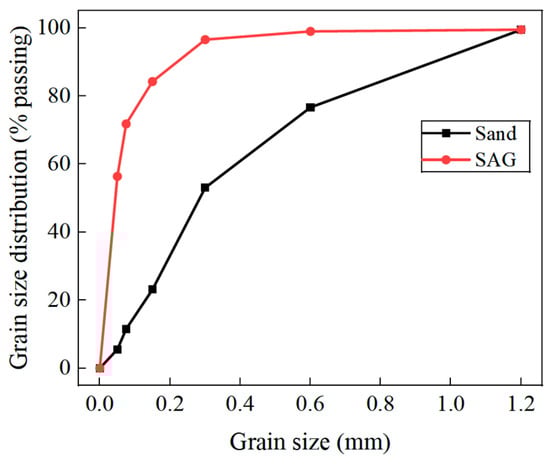
Figure 1.
Sand and scrap hydrophobic aerogel (SAG) particle size.
Table 2.
Main performance index of SAG.
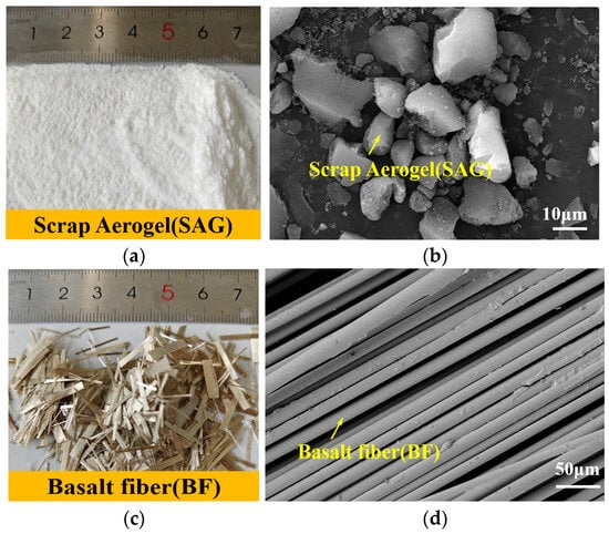
Figure 2.
(a) SAG; (b) SEM image of SAG; (c) basalt fibers; and (d) SEM image of basalt fiber.
Table 3.
Physical and mechanical properties of four types of BF.
2.1.2. Testing Equipment
To investigate the effect of scrap aerogel content on the thermal and mechanical properties of 3DCP, as well as the enhancement effect of basalt fibers of different lengths and diameters on the mechanical properties of 3DP-SAIC, two sets of experiments were designed in this paper.
SAIC: A mix without SAG was used as the control group (denoted as A0). In the other groups, aerogel replaced sand by volume at replacement levels of 10%, 15%, 20%, 25%, and 30%, respectively (denoted as A10, A15, A20, A25, and A30). The detailed mix proportions are presented in Table 4. The mix ratio is expressed as the weight of raw materials required to prepare six concrete test specimens for each test.
Table 4.
SAIC material mix ratios.
BF-SAIC: The A15 group in SAIC was used as the basis, in which the group without added basalt fibers was noted as A15, and the remaining four groups of BF of different lengths and diameters were designated as A15-1, A15-2, A15-3, and A15-4, respectively. The mixing ratios are shown in Table 5, with the BF dosage set at 0.5% in the previous study [37,44,45,46].
Table 5.
Fibre characteristics and blending ratio.
In both sets of tests, the prepared mixes were divided into two portions, one for standard casting (SC) and the other for 3DCP. The corresponding specimens were labeled as SC-SAIC and 3DP-SAIC, respectively.
2.2. Flowability Test
Flowability is one of the key factors determining the printability of 3D-printed concrete. A suitable flowability not only facilitates smooth extrusion of the printing material but also effectively prevents nozzle clogging and poor interlayer bonding, thereby significantly improving the formability and construction efficiency of printed components. To scientifically evaluate the flowability of 3DP-SAIC, the test method specified in “Test Method for Flow of Cement Mortar” (GB/T 2419-2005) [47] was adopted. A cement mortar flow table manufactured by Wuxi Jianyi Instrument Machinery Co., Ltd., Wuxi, China. was used to measure the flowability of the printing pastes. Three parallel tests were conducted for each mixture, and the average value was taken as the final flowability result to enhance the reliability of the data. The procedure for the jumping table test is as follows: (1) place a cone mold in the jumping table and fill it with the cement mixture; (2) remove the mold when the underlying table starts to work (the working condition for the table is 25 up and down vibrations within 25 ± 1 s; the mixture will spread out on the jumping table); and (3) when the table stops jumping, the average diameter of the spread concrete is measured in two perpendicular directions.
2.3. DCP Specimen Preparation
In the preparation process of 3D-printed concrete specimens, a pre-designed three-dimensional model was first imported into the printer controller to generate corresponding toolpaths and control instructions. Subsequently, raw materials were added into the concrete mixer in accordance with the predetermined mix proportion and thoroughly blended. The printing parameters were further adjusted based on the rheological behavior of the resulting paste. The printing parameters adopted in this study were as follows: nozzle diameter of 20 mm, layer height of 12.5 mm, printing horizontal traverse speed of 50 mm/s. After parameter setup, the homogeneously mixed paste was pumped to the printer nozzle, and the printing process was initiated. The printed specimens were initially cured at room temperature (approximately 20 °C) for one day, followed by continued curing in a standard environment maintained at 20 ± 1 °C and 95 ± 5% relative humidity for an additional six days.
To investigate the anisotropic characteristics of the 3D-printed concrete, the cured specimens were cut along three orthogonal directions: the X-axis was defined as the direction parallel to the printing path, the Y-axis was perpendicular to the X-axis within the horizontal plane, and the Z-axis was perpendicular to the X-Y plane. Two types of specimen sizes were obtained after cutting: 70.7 mm × 70.7 mm × 70.7 mm and 160 mm × 40 mm × 40 mm. All specimens were subsequently polished and cleaned to ensure smooth and flat surfaces. The entire fabrication process is illustrated in Figure 3. As a control group, conventionally cast concrete specimens were prepared using the same mix proportion, curing conditions, and dimensions as those of the 3D-printed concrete specimens, enabling a direct comparison of their mechanical and physical properties [48].
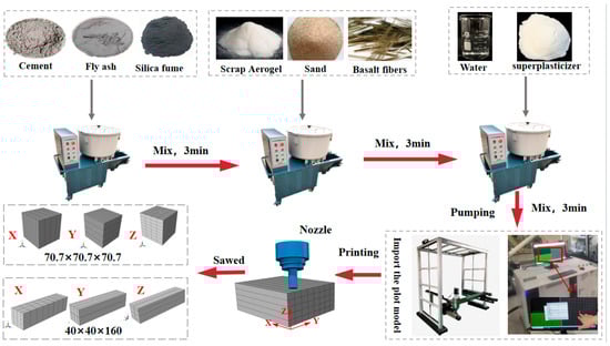
Figure 3.
Preparation of 3DP-SAIC specimens.
2.4. Thermal Performance Testing
Humidity plays an important role in the determination of thermal conductivity of test blocks. Therefore, in order to minimize the effect of humidity on the samples, they are dried before the thermal property tests. In this paper, an electric hot air drying oven (101-2ABS, Beijing Yong Guangming Medical Instrument Factory Co., Ltd., Beijing, China) was used to dry the test blocks at 105 ± 5 °C for more than 24 h to ensure that their weight remained constant. In addition, the thermal conductivity of the specimens was determined based on a fast thermal conductivity meter (Model DZZR-S, Nanjing Dazhan Institute of Electromechanical Technology Co., Ltd., Nanjing, China), and each specimen block was tested three times and the average value was taken as its thermal conductivity. Among them, the interval between thermal tests of the same specimen block was 2 h, and it was necessary to ensure that the sample was in close contact with the measuring probe during the test.
2.5. Mechanical Performance Test
This study mainly evaluated the mechanical properties of the specimens by testing their compressive and flexural strengths. The automatic constant-pressure testing machine (JYE-2000A, Beijing Keda Jingwei Technology Development Co., Ltd., Beijing, China), as shown in Figure 4 was used to measure both the compressive strength and the splitting tensile strength of the specimens. The cubic specimens used for these tests were all 70.7 mm × 70.7 mm × 70.7 mm in size, with six samples tested per group. In the splitting tensile test, steel cushion blocks were placed on the top and bottom surfaces of each specimen, as illustrated in Figure 4. Additionally, a motorized flexural testing machine (DKZ-5000, Tianjin Gangyuan Testing Instrument Factory Co., Ltd., Tianjin, China) was employed to determine the flexural strength of the specimens described in Section 2.4. The dimensions of the flexural test specimens were 160 mm × 40 mm × 40 mm.
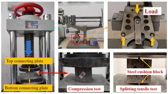
Figure 4.
3DCP-SAIC mechanical property tests.
2.6. FEM Analysis Methods
Based on the ABAQUS 2023 software, finite element models (FEM) were developed to simulate the behavior of 3D-printed concrete specimens under compressive loading and three-point bending loading. The geometric dimensions of these models are consistent with those of the experimental specimens described in Section 2.5, as shown in Figure 5a,b, respectively. Given the notable anisotropic properties of 3D-printed concrete, three different loading directions were considered in the simulations. In the figures, the gray regions represent aerogel concrete, which was modeled using the classical Concrete Damage Plasticity model. The material parameters for this model were derived by fitting the uniaxial compressive stress–strain curve data obtained from the cast concrete specimens in Section 2.5. Other parameters were set according to Ren et al. [49].
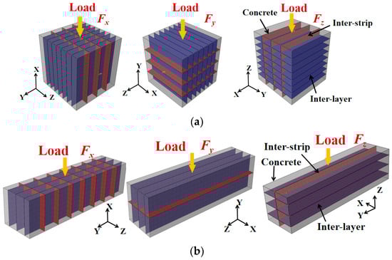
Figure 5.
(a) Finite element model of 3DCP specimen compression loading and (b) bending loading.
During the 3D printing construction process, due to its unique stacked-layer structure, two types of heterogeneous interfaces exist simultaneously in the 3D-printed specimens: inter-strip interfaces within the same plane (red area in Figure 5), and inter-layer interfaces within different planes (purple area in Figure 5), both of which ultimately lead to anisotropic 3D-printed structures [27]. To characterize the bonding performance at these interface regions, a bilinear cohesive zone model (CZM) was employed, with COH3D8 elements used for the simulation. The tensile strength and ultimate displacement parameters for both inter-layer and intra-strip interfaces were derived from the results of the interfacial splitting tensile tests presented in Section 2.5. The cohesive parameters are summarized in Table 6. In the table, σmax and τmax denote the tensile strength of the 3D-printed concrete matrix and the maximum shear stress at the interface, respectively. σs0 and σt0 represent the effective displacements at the onset of damage in the two shear directions. And σsf and σtf correspond to the effective displacements at complete failure in those directions.
Table 6.
Material properties of cohesion model interfaces.
2.7. Microscopic Property Evaluation
After crushing and drying the SAIC specimens, a golden coating was applied on the surface of the samples to create a conductive surface. And the micro-structure was observed using a scanning electron microscope (Sigma 300, ZEISS Co., Ltd., Bochingen, Germany).
3. Results and Discussion
3.1. Printability
In this study, the fluidity of the printing paste was evaluated based on its spread diameter in a flow table test. As shown in Figure 6a, the average spread diameters of samples A0, A10, A15, A20, A25, and A30 were 203 mm, 193 mm, 189 mm, 185 mm, 179 mm, and 176 mm, respectively. Compared to the control group A0, the spread diameters of A10, A15, A20, A25, and A30 decreased by 4.93%, 6.90%, 8.87%, 11.82%, and 13.30%, respectively. The primary reason for this reduction is that SAG has a high specific surface area. As the amount of SAG particles increases, more paste is required to coat the particles, leading to a decrease in the overall fluidity of the cementitious material. This conclusion is consistent with the findings by Ma et al. [32].
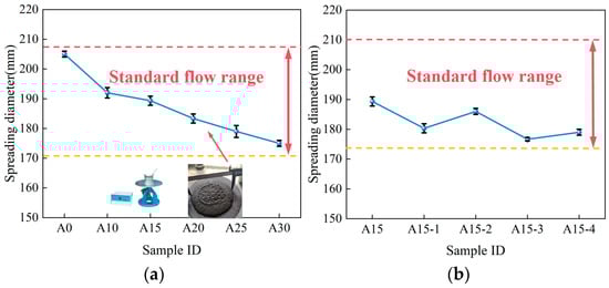
Figure 6.
Effect of SAG and BF on flowability of printed pastes: (a) SAG; (b) BF.
In addition, this paper further investigates the effect of basalt fiber length and diameter characteristics on the flowability of SAIC. As can be seen in Figure 6b, the addition of BF resulted in a decreasing trend in the overall fluidity of the printed paste compared to the control A15. Among them, the average spreading diameter of specimens A15-2, A15-4 increased by 3.14% and 1.32% compared to specimens A15-1, A15-3, respectively. That is, as the BF diameter decreases from 17 μm to 14 μm, the printed slurry flowability increases. This is mainly because the fiber diameter decreases and the surface area of the fibers decreases. The amount of cementitious material needed to encapsulate the fibers is reduced, and the fluidity of the cement particles is increased. Meanwhile, the average spread diameter of specimens A15-3, A15-4 decreased by 2.03% and 3.76% compared to specimens A15-1, A15-2, respectively. That is, as the BF length decreases from 12 mm to 6 mm, the printed slurry fluidity increases. This is mainly due to the complex network structure that longer fibers are more likely to form in the cement paste, impeding the flow of the paste.
In the printability assessment of 3D-printed concrete, the average spread diameter is considered one of the key indicators for evaluating the flowability of the printing paste. According to a related study [50], the recommended range for the average spread diameter in 3D-printed concrete is 174–210 mm. Within this range, the material exhibits sufficient flowability and shape stability to meet the performance requirements for successful 3D printing. As shown in Figure 6a,b, the average spread diameters of all the concrete printing pastes formulated in this study fall within this printable range, indicating that the proposed SAIC mixtures possess good printability.
3.2. Thermal Insulation Performance
The incorporation of SAG alters the internal pore structure of concrete materials, thereby affecting their dry density. Figure 7a illustrates the relationship between the dry density of concrete and the proportion of aerogel content. It can be observed that both SC and 3D-printed concrete specimens exhibit a decreasing trend in dry density as the aerogel content increases. Compared to the control group (A0), when 30% aerogel is added to the concrete, the dry densities of SC and 3D-printed concrete specimens decrease by 13.73% and 16.25%, respectively. This phenomenon is primarily attributed to the low bulk density characteristic of aerogel. In this study, aerogel was used to replace river sand on a volume-for-volume basis, resulting in a reduction in the overall density of the material as the aerogel content increases.
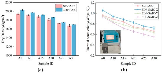
Figure 7.
Comparison of properties of SC-SAIC and 3DP-SAIC with different aerogel contents: (a) dry density; (b) thermal conductivity.
Additionally, the dry density of 3D-printed specimens is slightly higher than that of traditionally cast specimens. This difference is mainly due to the fact that traditional casting may result in air voids within the concrete due to inadequate compaction during vibration. In contrast, during the 3D printing process, the extrusion pressure applied by the print head provides initial compaction of the concrete material. Furthermore, during layer-by-layer stacking, the weight of the upper layers exerts additional compaction on the lower layers. This compaction effect reduces the porosity and defects within the material, thus enhancing its density.
The thermal insulation performance of concrete materials is closely related to their thermal conductivity. Our experimental results show that the thermal conductivities of both SC and 3D-printed concrete specimens decrease with increasing SAG content (Figure 7b), a trend consistent with the variation in dry density. Compared to the control group A0, which has a thermal conductivity of 0.9617 W/(m·K), the thermal conductivity of the SC-SAIC-A30 specimen (containing 30% waste aerogel) decreases to 0.6597 W/(m·K), representing a reduction of approximately 31.4%. This result is consistent with findings reported in the literature [28,43].
Furthermore, under the same aerogel content, the thermal conductivity of 3DCP specimens exhibits anisotropic characteristics, unlike the isotropic behavior of the SC-SAIC specimens. Among the different printing directions, the thermal conductivity of the 3DP-SAIC-X specimens is consistently slightly higher than that of the 3DP-SAIC-Y and 3DP-SAIC-Z specimens. Taking group A15 as an example, the thermal conductivities of SC, 3DP-X, 3DP-Y, and 3DP-Z are 0.8439 W/(m·K), 0.8856 W/(m·K), 0.7849 W/(m·K), and 0.72 W/(m·K), respectively. As the SAG content increases, the reduction in thermal conductivity becomes more pronounced for the 3DCP-Z direction. From sample A0 to A30, the thermal conductivity of 3DCP-Z decreases by 40.90%.
In order to further investigate how hydrophobic scarp silica aerogel (SAG) affects the pore structure of concrete materials, this study conducted microscopic observations using scanning electron microscopy (SEM) and energy-dispersive X-ray spectroscopy (EDS). The results show that the control sample A0 has relatively few pores and microcracks (Figure 8a). However, as the SAG content increases, the number of pores and cracks in the samples gradually increases (Figure 8b). This is mainly due to the fact that the hydrophobic SAG used in this study creates noticeable gaps at the interface between the aerogel particles and the cement matrix. These gaps may be caused by two factors: first, volume shrinkage during cement hydration [25]; second, the hydrophobic nature of the aerogel repels surrounding water, leading to the formation of cavities in some cases [51]. As a result, the overall porosity of the samples increases, which also explains the observed decrease in both dry density and thermal conductivity with increasing SAG content.
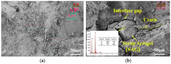
Figure 8.
SEM micrographs of (a) 3DP-SAIC-A0 and (b) 3DP-SAIC-A30.
In addition, this study also analyzed the thermal insulation performance and cost comparison between the SAIC and the virgin aerogel-incorporated concrete (AIC) prepared by Wang et al. [51]. This comparison strictly adheres to the experimental ratios specified in the literature. It investigates the thermal insulation performance of SAIC and AIC under identical conditions when the aerogel admixture ratio is the same. The results are shown in Figure 9. It can be seen that the thermal conductivity of both SAIC and AIC decreases significantly when the aerogel volume share increases from 0% to 30%. Specifically, the thermal conductivity of SAIC decreased by 34.02% while that of AIC decreased by 30.03%. This indicates that the SAG has the same significant effect as the virgin gel in improving the thermal insulation properties of concrete. Simultaneously, Figure 8b shows the cost comparison between SAIC and AIC when the aerogel content is the same for a cement volume of 1 m3. As the aerogel volume share increased from 0% to 30%, the cost of AIC increased sharply from $260.31 to $1048.65, while the cost of SAIC increased from $263.62 to $282.09. At 30% aerogel incorporation, the cost was significantly reduced by 73.10%. The main reason for this difference is the high price of virgin aerogel (about $27,77.8/m3), and the cost of AIC rises sharply as the aerogel incorporation increases. In SAIC, the cost of SAG is zero, and only the recycling cost of scrap aerogel needs to be considered. With the increase in aerogel incorporation, the dosage of sand decreases, which in turn leads to a smaller increase in the overall cost. Meanwhile, the recycling and reuse of SAG not only brings economic benefits, but also helps to reduce environmental pollution.
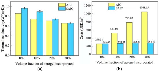
Figure 9.
Comparison of properties and costs for AIC and SAIC with different aerogel contents: (a) thermal conductivity of AIC Reference [51] and SAIC samples; (b) cost analysis of AIC Reference [51] and SAIC samples.
3.3. Compressive Strength
Figure 10a illustrates the effect of incorporating varying amounts of SAG on the compressive strength of SC-SAIC and 3DP-SAIC specimens. The results show that the compressive strength of both types of specimens decreases with increasing aerogel content. Compared to the control group A0, the compressive strength of SC specimens decreased by approximately 43.49% when 30% SAG was added to the concrete mix. Moreover, the compressive strength of 3DP-SAIC specimens was generally lower than that of SC specimens. This is primarily due to the fact that the 3D-printed concrete process may introduce non-uniform pores and defects, particularly at the inter-layer interfaces and along the seams between printing paths. These pores and defects can reduce the overall strength of the material and exhibit different distribution characteristics in various directions, leading to anisotropic mechanical properties. Notably, the compressive strength of 3DP-SAIC-X specimens was consistently slightly higher than that of 3DP-SAIC-Y and 3DP-SAIC-Z specimens. For instance, in Group A15, the SAIC compressive strengths of SC, 3DP-X, 3DP-Y, and 3DP-Z were 43.8 MPa, 41.3 MPa, 40.1 MPa, and 36.4 MPa, respectively. Compared to 3DP-X, the compressive strengths of 3DP-Y and 3DP-Z decreased by 5.71% and 16.89%, respectively, which aligns with the findings of Ma et al. [37].
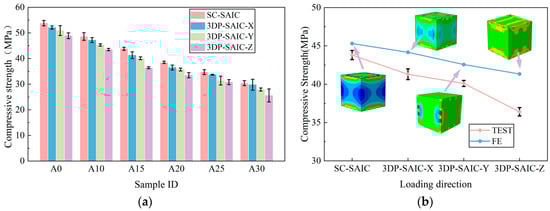
Figure 10.
Compressive strength analysis of SAIC samples: (a) Compressive strength of SC-SAIC and 3DP-SAIC in different directions as a function of SAG content; (b) comparison of compressive strength between experimental results (TEST) and finite element analysis (FE) for SC-SAIC and 3DP-SAIC.
In addition, a numerical simulation analysis of SAIC was conducted using the Abaqus 2023 software. As shown in Figure 10b, there is a high degree of consistency between the finite element simulation data and the test results. The specimens exhibited the highest compressive strength in the X-direction, followed by the Y-direction and then the Z-direction. This trend is consistent with the experimental observations, further confirming the validity and reliability of the finite element modeling approach presented in Section 2.7.
To more intuitively reveal the anisotropic compressive strength characteristics of 3D-printed concrete specimens, this study extracted damage contour maps in three loading directions for the 3DP-SAIC-A15 group under ultimate load conditions (Figure 11). The mixed-mode damage evolution method (MMIXDME) was employed to identify the types of damage. A MMIXDME value of −1 indicates no damage and is represented in blue; values between 0 and 0.5 indicate tensile failure, shown in green; and values between 0.5 and 1 represent shear failure, depicted in red. The analysis results demonstrate that under tri-directional loading, the primary failure mode at the interfaces is shear failure. This is mainly attributed to the lateral slip that occurs during compression at the Inter-strip (between printed filaments) and Inter-layer (between printed layers) regions, which are inherently weak zones in 3DP-SAIC.
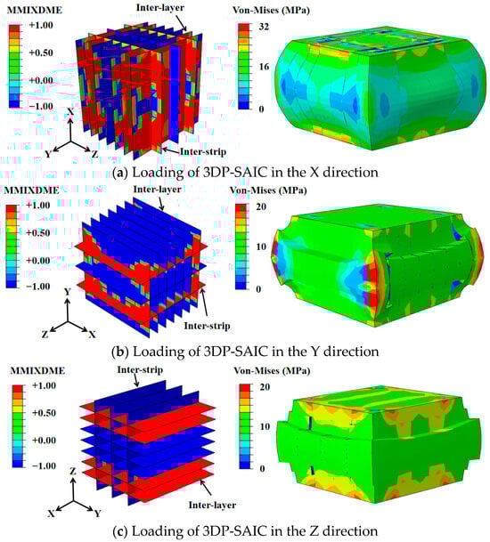
Figure 11.
Comparison of interfacial failure of 3DP-SAIC under compressive load: (a) X-direction load; (b) Y-direction load; (c) Z-direction load.
From the damage distribution, it can be observed that for the 3DP-SAIC-X specimen, although partial damage occurs at both the Inter-layer and Inter-strip interfaces, the core region remains largely intact without significant shear failure [52]. The specimen exhibits a bulging behavior during compression (Figure 11a), resulting in the highest vertical compressive strength. In contrast, the 3DP-SAIC-Y specimen shows damage primarily concentrated along the Inter-strip interfaces perpendicular to the loading direction, particularly near the top and bottom edges, where through-going shear cracks develop, leading to distinct shear sliding features (Figure 11b). For the 3DP-SAIC-Z specimen, damage is predominantly found across multiple Inter-layer interfaces, forming through-going shear slip planes in the central region (Figure 11c), which results in the lowest compressive strength. In summary, the compressive strength of 3DP-SAIC exhibits significant anisotropy depending on the loading direction, following the order: X-direction > Y-direction > Z-direction.
In this study, the compressive strength of basalt fiber (BF)-reinforced SAIC was investigated. Figure 12 illustrates the effect of four different BF sizes on the compressive strength enhancement of both SC-SAIC and 3DP-SAIC specimens. As shown in the figure, the incorporation of BFs led to an increase in the compressive strength of both specimen types. However, the overall enhancement effect was relatively modest. This limited improvement can be attributed to two main factors: first, the low volume fraction of BFs used in the mix prevents the formation of an effective three-dimensional fiber network within the SAIC matrix, thereby limiting their ability to inhibit crack propagation. Second, during uniaxial compression, concrete primarily fails in shear, and BFs have a relatively minor influence on shear damage resistance. In the case of 3DP-SAIC-X, samples A15-3 and A15-4 exhibited compressive strength increases of 4.44% and 3.61%, respectively, compared to samples A15-1 and A15-2. This suggests that longer BFs, at the same diameter, are more effective in forming a three-dimensional network structure within the matrix, which enhances crack bridging and stress dispersion, thereby improving compressive performance. Additionally, when comparing samples with the same BF length, the compressive strengths of A15-1 and A15-3 were found to be 1.58% and 2.40% higher than those of A15-2 and A15-4, respectively. This indicates that, for fibers of equal length, larger diameters provide greater pull-out resistance, which helps to more effectively constrain crack propagation and thus improves the toughness and crack resistance of the SAIC.
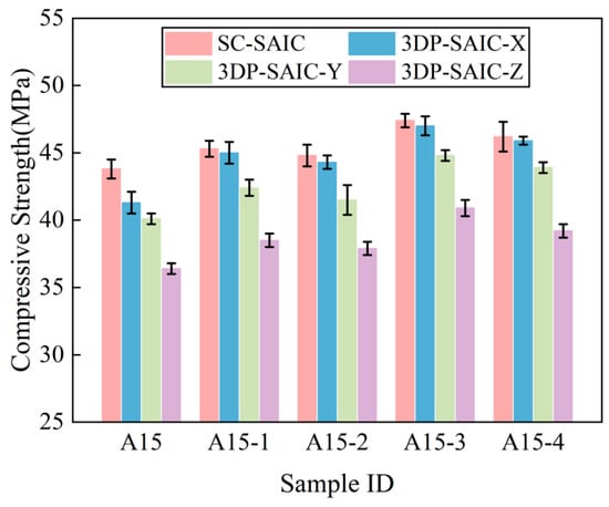
Figure 12.
Compressive strength of SC-SAIC and 3DP-SAIC with different BF lengths and diameters.
3.4. Flexural Strength
Flexural strength is a critical mechanical property that ensures the safety and reliability of building structures [52]. As shown in Figure 13a, the flexural strength of both SC-SAIC and 3DP-SAIC samples decreases with increasing (SAG) content, a trend consistent with that observed in compressive strength. For instance, when the SAG content reached 30%, the flexural strength of SC-SAIC decreased by approximately 43.76% compared to the control group (A0), which contained no SAG. In contrast to the isotropic behavior of SC-SAIC, the 3DP-SAIC samples exhibited anisotropic flexural performance. Notably, this anisotropy presented a distinct orientation order of Y > Z > X. For example, in the A15 group (15% SAG), the average flexural strengths of 3DP-SAIC-X, 3DP-SAIC-Y, and 3DP-SAIC-Z were 7.23 MPa, 8.47 MPa, and 8.03 MPa, respectively. Compared to the Y-direction, the flexural strengths in the X and Z directions decreased by 14.64% and 5.19%, respectively. Furthermore, finite element simulation analysis corroborated the observed trends, as illustrated in Figure 13b. The simulation results demonstrate that the flexural strength is highest in the Y-direction, followed by the Z-direction, and lowest in the X-direction.
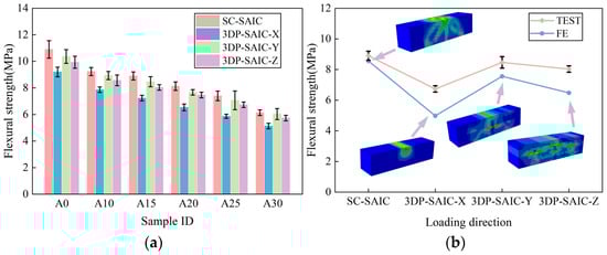
Figure 13.
Experimental and numerical analysis of flexural behavior in SC-SAIC and 3DP-SAIC: (a) flexural strength of SC-SAIC and 3DP-SAIC with different SAG content; (b) validation of anisotropic flexural response in 3DP-SAIC via finite element.
To further investigate the anisotropic flexural behavior of 3DCP, this study extracted the damage distribution patterns along the X, Y, and Z directions at the ultimate load state for the 3DP-SAIC-A15 (Figure 14). The results indicate significant differences in failure modes and mechanical mechanisms under different loading orientations. Under bending in the X direction (Figure 14a), the flexural strength is primarily governed by both the tensile strength of the SAIC and the Inter-strip tensile resistance. Due to the susceptibility of the interface to tensile stress, damage tends to concentrate in the green regions shown in the figure. When loaded along the Y direction (Figure 14b), the flexural strength is determined by the tensile strength of SAIC and the Inter-strip shear resistance. Since shear failure is less severe than tensile failure, the flexural strength in the Y direction is higher than that in the X direction. For loading in the Z direction (Figure 14c), the flexural strength depends on the tensile capacity of SAIC and the inter-layer shear resistance. Multiple potential shear slip planes (as indicated by the red regions in Figure 14c) lead to a decrease in flexural strength compared to the Y direction, although it remains slightly higher than in the X direction. Overall, the flexural strength of 3DP-SAIC exhibits a clear anisotropic pattern, following the order Y > Z > X.
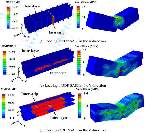
Figure 14.
Comparison of interfacial failure of 3DP-SAIC under flexure: (a) X-direction load; (b) Y-direction load; (c) Z-direction load.
Figure 15a illustrates the interfacial bonding between basalt fibers (BF) and the cementitious matrix. SEM images reveal strong adhesion at the fiber–matrix interface, indicating the formation of an effective mechanical interlock that contributes to the reinforcement mechanism. During fracture and fiber pull-out processes, significant energy dissipation occurs, which helps constrain deformation and inhibit crack propagation, thereby substantially enhancing the overall mechanical performance of the material [37].
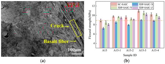
Figure 15.
Impact of basalt fiber characteristics on flexural strength of SC-SAIC and 3DP-SAIC: (a) SEM image of fracture surface in A15-1; (b) flexural strength with different BF lengths and diameters.
To further investigate the influence of BF characteristics—specifically fiber length and diameter—on the flexural behavior of SAIC, four different BF types were incorporated into both SC-SAIC and 3DP-SAIC samples within the A15 group, and their flexural strengths were experimentally evaluated (Figure 15b). The results demonstrate that BF incorporation effectively improves the flexural strength of both casting and 3D-printed specimens. Notably, the A15-3 group exhibited the most pronounced enhancement. This improvement can be attributed to the superior stress transfer capability of 12 mm BF compared to 6 mm BF, resulting from their enhanced interaction with the cementitious matrix. Furthermore, BF with a diameter of 17 μm provides a larger surface area for better interfacial bonding than 14 μm BF, thereby enhancing the reinforcing effect. Compared to the control group, the flexural strengths of SC-SAIC, 3DP-SAIC-X, 3DP-SAIC-Y, and 3DP-SAIC-Z in the A15-3 group increased by 22.85%, 24.42%, 24.02%, and 26.97%, respectively. The enhancement is particularly evident in the Z direction, which is perpendicular to the printing direction. During the printing process, some fibers tend to align along the extrusion direction (X-axis), enabling them to directly resist tensile stresses and interlayer shear stresses acting along the Z direction. As a result, the flexural strength in the Z direction is significantly improved.
4. Conclusions
In this study, scrap aerogel and basalt fibers were incorporated into 3D concrete printing, and both experimental and numerical simulation approaches were employed to investigate their effects on the thermal insulation and mechanical properties of the resulting material. The main conclusions are summarized as follows:
(1) Due to the low density and porous structure of aerogels, the incorporation of waste aerogels reduces the flowability of 3D-printed concrete. However, when incorporating waste aerogels at volumes ranging from 0 to 30%, the 3D-printed concrete still maintains good printability.
(2) The thermal insulation performance of 3D-printed scrap-aerogel-incorporated concrete (3DP-SAIC) exhibited pronounced anisotropy. Specifically, the thermal conductivity perpendicular to the printing direction was the lowest. When the volume fraction of scrap aerogel reached 30%, the thermal conductivity in this direction was reduced by up to 40.90%.
(3) 3DP-SAIC also displayed significant mechanical anisotropy. Compressive strength was highest in the X-direction (along the printing layers), whereas flexural strength was superior in the Y- and Z-directions (perpendicular to the printing layers). This anisotropic behavior primarily resulted from the relatively weak interfacial bonding between printed layers and adjacent filaments during the printing process.
(4) BF significantly enhances the mechanical properties of 3DP-SAIC. The test results indicate that while its improvement in compressive strength is limited, it has a pronounced effect on enhancing flexural strength. When using BF with a length of 12 mm and a diameter of 17 μm, the maximum increase in flexural strength measured perpendicular to the print direction reached 26.97%.
(5) Spent aerogel (SAG) demonstrates comparable effectiveness to virgin aerogel in enhancing concrete thermal insulation properties. The thermal conductivity of concrete containing spent aerogel (SAIC) closely resembles that of aerogel-containing concrete (AIC), yet its manufacturing costs are significantly reduced. When the volume content of spent aerogel filler reaches 30%, SAIC costs are 73% lower than AIC costs. This offers substantial cost savings for engineering applications.
Author Contributions
Conceptualization, X.Z. (Xiaowei Zhu); Methodology, X.Z. (Xudong Zhang), W.W. and P.Z.; Software, X.Z. (Xudong Zhang); Validation, J.Z., S.Z. and H.Y.; Formal Analysis, J.Z.; Investigation, X.Z. (Xudong Zhang), M.C. and P.Z.; Resources, X.Z. (Xiaowei Zhu); Data Curation, X.Z. (Xudong Zhang) and M.C.; Writing—Original Draft, X.Z. (Xudong Zhang); Writing—Review & Editing, X.Z. (Xiaowei Zhu); Visualization, S.Z. and W.W.; Supervision, X.Z. (Xiaowei Zhu) and H.Y.; Project Administration, X.Z. (Xiaowei Zhu); Funding acquisition, X.Z. (Xiaowei Zhu). All authors have read and agreed to the published version of the manuscript.
Funding
The authors would like to acknowledge the financial support from the key projects of Higher Education Institutions in Henan Province (No. 25B560011), Henan Key Laboratory of Grain and oil storage facility & safety research project (No. 2023KF09), and Cultivation Project of Tuoxin Team in Henan University of Technology (No. 2024TXTD15).
Data Availability Statement
The original contributions presented in this study are included in the article. Further inquiries can be directed to the corresponding author.
Conflicts of Interest
Authors Jicheng Zhang and Hongxia Yang were employed by the company Gongyi Van-Research Innovation Composite Material Co., Ltd. Author Miao Chen was employed by the company The First Company of China Construction Sixth Engineering Bureau Co., Ltd. Author Pei Zhao was employed by the company Sinomach Zhongxing Enfineering Consulting Co., Ltd. The remaining authors declare that the research was conducted in the absence of any commercial or financial relationships that could be construed as potential conflicts of interest.
References
- Hou, H.; Feng, X.; Zhang, Y.; Bai, H.; Ji, Y.; Xu, H. Energy-Related Carbon Emissions Mitigation Potential for the Construction Sector in China. Environ. Impact Assess. Rev. 2021, 89, 106599. [Google Scholar] [CrossRef]
- Lai, K.E.; Abdul Rahiman, N.; Othman, N.; Ali, K.N.; Lim, Y.W.; Moayedi, F.; Mat Dzahir, M.A. Quantification Process of Carbon Emissions in the Construction Industry. Energy Build. 2023, 289, 113025. [Google Scholar] [CrossRef]
- Zhu, C.; Guo, G.; Su, S.; Hong, J.; Li, X. Multiple Accounting of Carbon Emission Responsibility in the Construction Sector under Different Principles: A Study from China. Renew. Sustain. Energy Rev. 2023, 186, 113651. [Google Scholar] [CrossRef]
- Hao, J.L.; Ma, W. Evaluating Carbon Emissions of Construction and Demolition Waste in Building Energy Retrofit Projects. Energy 2023, 281, 128201. [Google Scholar] [CrossRef]
- Adamczyk, J.; Dylewski, R. The Impact of Thermal Insulation Investments on Sustainability in the Construction Sector. Renew. Sustain. Energy Rev. 2017, 80, 421–429. [Google Scholar] [CrossRef]
- Chau, C.K.; Leung, T.M.; Ng, W.Y. A Review on Life Cycle Assessment, Life Cycle Energy Assessment and Life Cycle Carbon Emissions Assessment on Buildings. Appl. Energy 2015, 143, 395–413. [Google Scholar] [CrossRef]
- Sun, J.; Liu, S.; Ma, Z.; Wang, D.; Wang, Y.; Zhao, H.; Huang, B.; Saafi, M.; Wang, X. 3D Printed Lightweight Concrete Containing Surface Pretreated Coal Gangue. Case Stud. Constr. Mater. 2024, 20, e02906. [Google Scholar] [CrossRef]
- Baigarina, A.; Shehab, E.; Ali, M.H. Construction 3D Printing: A Critical Review and Future Research Directions. Prog. Addit. Manuf. 2023, 8, 1393–1421. [Google Scholar] [CrossRef]
- Zhu, X.; Jiang, Z. Reuse of Waste Rubber in Pervious Concrete: Experiment and DEM Simulation. J. Build. Eng. 2023, 71, 106452. [Google Scholar] [CrossRef]
- Zhu, B.; Wang, Y.; Sun, J.; Wei, Y.; Ye, H.; Zhao, H.; Wang, X. An Experimental Study on the Influence of Waste Rubber Particles on the Compressive, Flexural and Impact Properties of 3D Printable Sustainable Cementitious Composites. Case Stud. Constr. Mater. 2023, 19, e02607. [Google Scholar] [CrossRef]
- Ma, Q.; Mao, Z.; Lei, M.; Zhang, J.; Luo, Z.; Li, S.; Du, G.; Li, Y. Experimental Investigation of Concrete Prepared with Waste Rubber and Waste Glass. Ceram. Int. 2023, 49, 16951–16970. [Google Scholar] [CrossRef]
- Çelik, A.İ.; Tunç, U.; Bahrami, A.; Karalar, M.; Othuman Mydin, M.A.; Alomayri, T.; Özkılıç, Y.O. Use of Waste Glass Powder toward More Sustainable Geopolymer Concrete. J. Mater. Res. Technol. 2023, 24, 8533–8546. [Google Scholar] [CrossRef]
- Lu, J.-X.; Yan, X.; He, P.; Poon, C.S. Sustainable Design of Pervious Concrete Using Waste Glass and Recycled Concrete Aggregate. J. Clean. Prod. 2019, 234, 1102–1112. [Google Scholar] [CrossRef]
- Leles da Silva, M.D.; Silva, L.F.; Toralles, B.M.; Cardoso, F.A.R.; Corso, M.; Soto Herek Rezende, L.C. Building a Sustainable Future: The Role of Additive Manufacturing in Civil Construction. Case Stud. Constr. Mater. 2024, 20, e02976. [Google Scholar] [CrossRef]
- Luo, Q.-L.; Yu, K.-K.; Long, W.-J.; Zheng, S.-Y.; Geng, S.-Y.; Feng, G.-L.; Wang, H.-L.; Qiu, Z.-H. Influence of Different Types of Superabsorbent Polymers on Fresh Mechanical Properties and Interlayer Adhesion of 3D Printed Concrete. Case Stud. Constr. Mater. 2024, 21, e03517. [Google Scholar] [CrossRef]
- Mi, R.; Pan, G.; Liew, K.M.; Kuang, T. Utilizing Recycled Aggregate Concrete in Sustainable Construction for a Required Compressive Strength Ratio. J. Clean. Prod. 2020, 276, 124249. [Google Scholar] [CrossRef]
- Delgado Camacho, D.; Clayton, P.; O’Brien, W.; Ferron, R.; Juenger, M.; Salamone, S.; Seepersad, C. Applications of Additive Manufacturing in the Construction Industry—A Prospective Review. In Proceedings of the 34th International Symposium on Automation and Robotics in Construction, Taipei, Taiwan, 28 June–1 July 2017. [Google Scholar]
- Tabassum, T.; Ahmad Mir, A. A Review of 3d Printing Technology-the Future of Sustainable Construction. Mater. Today Proc. 2023, 93, 408–414. [Google Scholar] [CrossRef]
- Pessoa, S.; Guimarães, A.S.; Lucas, S.S.; Simões, N. 3D Printing in the Construction Industry—A Systematic Review of the Thermal Performance in Buildings. Renew. Sustain. Energy Rev. 2021, 141, 110794. [Google Scholar] [CrossRef]
- Moschetti, R.; Brattebø, H.; Sparrevik, M. Exploring the Pathway from Zero-Energy to Zero-Emission Building Solutions: A Case Study of a Norwegian Office Building. Energy Build. 2019, 188–189, 84–97. [Google Scholar] [CrossRef]
- Shah, S.N.; Mo, K.H.; Yap, S.P.; Radwan, M.K.H. Towards an Energy Efficient Cement Composite Incorporating Silica Aerogel: A State of the Art Review. J. Build. Eng. 2021, 44, 103227. [Google Scholar] [CrossRef]
- Zhang, H.; Yang, J.; Wu, H.; Fu, P.; Liu, Y.; Yang, W. Dynamic Thermal Performance of Ultra-Light and Thermal-Insulative Aerogel Foamed Concrete for Building Energy Efficiency. Sol. Energy 2020, 204, 569–576. [Google Scholar] [CrossRef]
- Liu, Z.; Zang, C.; Zhang, S.; Zhang, Y.; Yuan, Z.; Li, H.; Jiang, J. Atmospheric Drying Preparation and Microstructure Characterization of Fly Ash Aerogel Thermal Insulation Material with Superhydrophobic. Constr. Build. Mater. 2021, 303, 124425. [Google Scholar] [CrossRef]
- Cheng, B.; Gu, X.; Gao, Y.; Ma, P.; Kang, S. Thermal and Waterproof Properties of Foamed Concrete with Nano SiO2 Aerogel and Organosilicon Waterproofing Agent. Adv. Mater. Sci. Eng. 2022, 2022, 3054214. [Google Scholar] [CrossRef]
- Liu, P.; Wu, W.; Du, B.; Tian, G.H.; Gong, Y.F. Study on the Heat and Moisture Transfer Characteristics of Aerogel-Enhanced Foam Concrete Precast Wall Panels and the Influence of Building Energy Consumption. Energy Build. 2022, 256, 111707. [Google Scholar] [CrossRef]
- Yoon, H.-S.; Lim, T.-K.; Jeong, S.-M.; Yang, K.-H. Thermal Transfer and Moisture Resistances of Nano-Aerogel-Embedded Foam Concrete. Constr. Build. Mater. 2020, 236, 117575. [Google Scholar] [CrossRef]
- Zeng, Q.; Mao, T.; Li, H.; Peng, Y. Thermally Insulating Lightweight Cement-Based Composites Incorporating Glass Beads and Nano-Silica Aerogels for Sustainably Energy-Saving Buildings. Energy Build. 2018, 174, 97–110. [Google Scholar] [CrossRef]
- Gao, T.; Jelle, B.P.; Gustavsen, A.; Jacobsen, S. Aerogel-Incorporated Concrete: An Experimental Study. Constr. Build. Mater. 2014, 52, 130–136. [Google Scholar] [CrossRef]
- Khamidi, M.F.; Glover, C.; Farhan, S.A.; Puad, N.H.A.; Nuruddin, M.F. Effect of Silica Aerogel on the Thermal Conductivity of Cement Paste for the Construction of Concrete Buildings in Sustainable Cities. WIT Trans. Built Environ. 2014, 137, 665–674. [Google Scholar] [CrossRef]
- Fickler, S.; Milow, B.; Ratke, L.; Schnellenbach-Held, M.; Welsch, T. Development of High Performance Aerogel Concrete. Energy Procedia 2015, 78, 406–411. [Google Scholar] [CrossRef]
- Tsioulou, O.; Ayegbusi, J.; Lampropoulos, A. Experimental Investigation on Thermal Conductivity and Mechanical Properties of a Novel Aerogel Concrete. In High Tech Concrete: Where Technology and Engineering Meet; Hordijk, D.A., Luković, M., Eds.; Springer International Publishing: Cham, Switzerland, 2018; pp. 125–131. [Google Scholar]
- Ma, G.; Ruhan, A.; Xie, P.; Pan, Z.; Wang, L.; Hower, J.C. 3D-Printable Aerogel-Incorporated Concrete: Anisotropy Influence on Physical, Mechanical, and Thermal Insulation Properties. Constr. Build. Mater. 2022, 323, 126551. [Google Scholar] [CrossRef]
- Kwalramani, M.A.; Syed, Z.I. Application of Nanomaterials to Enhance Microstructure and Mechanical Properties of Concrete. Int. J. Integr. Eng. 2018, 10, 98–104. [Google Scholar] [CrossRef]
- Rageh, B.O.; El-Mandouh, M.A.; Elmasry, A.H.; Attia, M.M. Flexural Behavior of RC Beams Strengthened with GFRP Laminate and Retrofitting with Novelty of Adhesive Material. Buildings 2022, 12, 1444. [Google Scholar] [CrossRef]
- Liu, C.; Yue, S.; Zhou, C.; Sun, H.; Deng, S.; Gao, F.; Tan, Y. Anisotropic Mechanical Properties of Extrusion-Based 3D Printed Layered Concrete. J. Mater. Sci. 2021, 56, 16851–16864. [Google Scholar] [CrossRef]
- Felekoğlu, B.; Tosun, K.; Baradan, B. Effects of Fibre Type and Matrix Structure on the Mechanical Performance of Self-Compacting Micro-Concrete Composites. Cem. Concr. Res. 2009, 39, 1023–1032. [Google Scholar] [CrossRef]
- Ma, G.; Li, Z.; Wang, L.; Wang, F.; Sanjayan, J. Mechanical Anisotropy of Aligned Fiber Reinforced Composite for Extrusion-Based 3D Printing. Constr. Build. Mater. 2019, 202, 770–783. [Google Scholar] [CrossRef]
- Ma, G.; Dou, C.; Wang, L.; Wang, F.; Li, Z. Mechanical Improvement of Basalt Fiber Reinforced Cementitious Material for Binder Jetting 3D Printing. Addit. Manuf. 2025, 100, 104688. [Google Scholar] [CrossRef]
- Hambach, M.; Rutzen, M.; Volkmer, D. Chapter 5—Properties of 3D-Printed Fiber-Reinforced Portland Cement Paste. In 3D Concrete Printing Technology; Sanjayan, J.G., Nazari, A., Nematollahi, B., Eds.; Butterworth-Heinemann: Waltham, MA, USA, 2019; pp. 73–113. ISBN 978-0-12-815481-6. [Google Scholar]
- Li, Y.-F.; Liang, Y.-F.; Syu, J.-Y.; Huang, C.-H.; Tsai, Y.-K.; Lok, M.-H. Static and Dynamic Mechanical Characteristics of 3D-Printed Anisotropic Basalt Fiber-Reinforced Cement Mortar. J. Build. Eng. 2025, 100, 111692. [Google Scholar] [CrossRef]
- Guo, Z.; Yang, R.; Wang, T.; An, L.; Ren, S.; Zhou, C. Cost-Effective Additive Manufacturing of Ambient Pressure-Dried Silica Aerogel. J. Manuf. Sci. Eng. 2021, 143, 011011. [Google Scholar] [CrossRef]
- Zhu, X.; Yang, L.; Jiang, Q.; Zhang, X.; Jing, H.; Zheng, S.; Hao, H.; Jin, L. Preparation and Performance Evaluation of Low-Cost and High-Performance Scrap SiO2 Aerogel Insulation Mortar (SAIM). Constr. Build. Mater. 2025, 490, 142559. [Google Scholar] [CrossRef]
- Kim, S.; Seo, J.; Cha, J.; Kim, S. Chemical Retreating for Gel-Typed Aerogel and Insulation Performance of Cement Containing Aerogel. Constr. Build. Mater. 2013, 40, 501–505. [Google Scholar] [CrossRef]
- Yu, S.; Bale, H.; Park, S.; Hwang, J.Y.; Hong, S.H. Anisotropic Microstructure Dependent Mechanical Behavior of 3D-Printed Basalt Fiber-Reinforced Thermoplastic Composites. Compos. Part B Eng. 2021, 224, 109184. [Google Scholar] [CrossRef]
- Varela, H.; Barluenga, G.; Sonebi, M. Evaluation of Basalt Fibers and Nanoclays to Enhance Extrudability and Buildability of 3D-Printing Mortars. J. Build. Eng. 2024, 97, 110776. [Google Scholar] [CrossRef]
- Zhang, C.; Wang, Y.; Zhang, X.; Ding, Y.; Xu, P. Mechanical Properties and Microstructure of Basalt Fiber-Reinforced Recycled Concrete. J. Clean. Prod. 2021, 278, 123252. [Google Scholar] [CrossRef]
- GB/T 2419-2005; National Cement Standardization Technical Committee, Test method for fluidity of cement mortar. China Standards Press: Beijing, China, 2005. (In Chinese)
- Wu, H.; Zhang, H.; Zhang, G.; Liu, J.; Liu, Z.; Du, F. Study on Preparation and Performance of Advanced Aerogel Foamed Concrete with Ultra-Light Aerogel. Constr. Build. Mater. 2023, 366, 130166. [Google Scholar] [CrossRef]
- Ren, G.M.; Wu, H.; Fang, Q.; Liu, J.Z. Effects of Steel Fiber Content and Type on Dynamic Compressive Mechanical Properties of UHPCC. Constr. Build. Mater. 2018, 164, 29–43. [Google Scholar] [CrossRef]
- Li, H.; Wei, J.; Khayat, K.H. 3D Printing of Fiber-Reinforced Calcined Clay-Limestone-Based Cementitious Materials: From Mixture Design to Printability Evaluation. Buildings 2024, 14, 1666. [Google Scholar] [CrossRef]
- Wang, Y.; Huang, J.; Wang, D.; Liu, Y.; Zhao, Z.; Liu, J. Experimental Investigation on Thermal Conductivity of Aerogel-Incorporated Concrete under Various Hygrothermal Environment. Energy 2019, 188, 115999. [Google Scholar] [CrossRef]
- Xiao, J.; Liu, H.; Ding, T. Finite Element Analysis on the Anisotropic Behavior of 3D Printed Concrete under Compression and Flexure. Addit. Manuf. 2021, 39, 101712. [Google Scholar] [CrossRef]
Disclaimer/Publisher’s Note: The statements, opinions and data contained in all publications are solely those of the individual author(s) and contributor(s) and not of MDPI and/or the editor(s). MDPI and/or the editor(s) disclaim responsibility for any injury to people or property resulting from any ideas, methods, instructions or products referred to in the content. |
© 2025 by the authors. Licensee MDPI, Basel, Switzerland. This article is an open access article distributed under the terms and conditions of the Creative Commons Attribution (CC BY) license (https://creativecommons.org/licenses/by/4.0/).