Abstract
The standing seam metal roof system is wind-sensitive due to its light weight and decreasing stiffness as the span increases, and in recent years there have been a number of wind-exposed damages to the structures where these roof systems have been applied. In order to study the wind-uplifted resistance reliability of different types of standing seam metal roof systems, and then to evaluate their safety level, a reliability analysis framework was developed. The proposed approach integrates the Latin Hypercube Sampling–Monte Carlo Simulation (LHS–MCS) method to assess the wind-uplifted resistance reliability of standing seam metal roof systems. Taking Jinan Yaoqiang International Airport Terminal Building’s standing seam Al-Mg-Mn roof system and Urumqi Tianshan International Airport Transportation Center’s standing seam Al-Zn-plated steel roof system as the objects of research, the research was carried out from the aspects of wind uplift test, wind tunnel test, finite element simulation, and wind-uplifted resistance reliability analysis. The study shows the following: the wind-uplifted resistance bearing capacity of the roof systems is significantly affected by the width of the roof panel, the spacing of the fixed support, the thickness of the roof panel, and the diameter of end interlocking; the effects of the differences in structural parameters and roof types are eliminated by the introduction of a damage index, and the failure forms of different types of roof systems can be unified, and the corresponding limit state function can then be deduced; based on the LHS–MCS method, the reliability indexes of the two common types of standing seam metal roof systems were obtained to be 3.0975 and 3.2850, respectively, which are lower than the requirements of the code for the first safety level, and it is recommended that reinforcement measures be prioritized at the connection points between roof panel and support, such as reducing the spacing of the fixed support or decreasing the diameter of end interlocking, to improve the structural safety. The above study can provide a reference for the safety level assessment, wind resistant design, and sustainable operation and maintenance of different types of standing seam metal roof systems.
1. Introduction
With the continuous strengthening of China’s economic capacity, the rapid development of large-scale public buildings—such as airport terminals, high-speed railway stations, and convention and exhibition centers—has led to the increasingly widespread adoption of long-span roof structures as primary structural systems. Among these, standing seam metal roof systems have been extensively employed due to their light weight, ease of construction, and aesthetically pleasing appearance [1,2]. As architectural functions increasingly demand expansive spatial configurations, such structures exhibit markedly larger spans and progressively reduced stiffness, rendering them highly susceptible to wind uplift damage under strong wind conditions [3,4,5,6]. Unlike the transient and impulsive characteristics of seismic loads [7,8,9], wind actions typically display pronounced dynamic effects and long-period vibration responses. Consequently, investigating the wind-resistant performance of such structural systems is of critical importance. Depending on the differences in roof panel materials, forms of the fixed supports, and interlocking mechanisms, the most commonly used standing seam metal roof systems can be classified into three main types: standing seam Al-Mg-Mn roof systems, standing seam steel roof systems, and standing seam Al-Zn-plated steel roof systems. The typical connection details of these systems are illustrated in Figure 1 [10].

Figure 1.
Construction details at connection points between commonly used types of standing seam metal roof systems. (a) Standing seam Al-Mg-Mn roof system. (b) Standing seam steel roof system. (c) Standing seam Al-Zn-plated steel roof system.
As a key metric for evaluating structural performance, reliability refers to the ability of a system to fulfill its intended function under specified conditions for a prescribed period of time. Existing research on the wind-uplifted resistance reliability of roof systems has yielded valuable insights from numerous scholars. Rosowsky et al. [11,12] analyzed the reliability of pitched roofs in three common types of residential buildings by considering two failure modes: roof panel failure and failure at the roof-to-wall connections. Shanmugam et al. [13] developed a predictive model for roof panel performance under wind loads, which facilitates the determination of the statistical properties of panel resistance and the assessment of reliability. Yang et al. [14] established a resistance degradation model for light-steel roof connections to calculate the time-variant reliability of connections in coastal regions, enabling a probabilistic evaluation of wind-resistant performance. Li et al. [15,16] proposed a reliability assessment method for the wind-uplifted resistance of standing seam steel roof systems and validated its effectiveness through engineering case studies. These studies provide an important foundation for the reliability assessment of specific roof systems. However, for other standing seam metal roof systems widely used in large public buildings—such as the standing seam Al–Mg–Mn roof and the standing seam Al-Zn-plated steel roof—the roof panel materials, the fixed supports, and numerous complex connection types differ substantially from those in the aforementioned studies. These differences limit the applicability of existing research findings. Consequently, further in-depth investigation into the wind-uplifted resistance reliability of common standing seam metal roof systems remains necessary.
Furthermore, conducting a wind-uplifted resistance reliability analysis of standing seam metal roof systems requires first identifying their failure forms and corresponding limit state functions. Previous studies [17,18] have shown that, for standing seam metal roofs without anti-wind clips, the failure form under wind loads is the tripping failure of the roof panels from their supports at the standing seams. Based on the distinct structural characteristics of different connection details and the associated roof deformation behavior, Wu [19] proposed using the mid-span vertical displacement as a quantitative indicator of metal roof failure. Considering that variations in roof structural parameters can lead to differences in displacement response under loading, a damage index should be introduced to eliminate the influence of these parameters. This approach enables the establishment of a unified failure criterion and its corresponding limit state function.
Once the failure forms of the roof system and their corresponding limit state functions are identified, the wind-uplifted resistance reliability of standing seam metal roof systems can be evaluated using the appropriate reliability analysis methods. The Latin Hypercube Sampling–Monte Carlo Simulation (LHS–MCS) technique is an efficient statistical sampling method that reduces computational effort through a stratified strategy while maintaining the desired level of accuracy. Specifically, the probability distribution of each input variable is divided into equal-probability intervals, from which random samples are drawn to ensure comprehensive coverage of the entire distribution range. Based on this approach, a wind-uplifted resistance reliability analysis framework for standing seam metal roof systems is developed to determine the failure probability Pf and reliability index β for Al-Mg-Mn roof systems and Al-Zn-plated steel roof systems.
Accordingly, the reliability analysis procedure for standing seam metal roof systems under wind loads is as follows. First, the most unfavorable characteristic wind load values are determined in accordance with the load design code [20] and the wind tunnel test results, from which the random parameters of wind loads and structural properties of the roof system are established. Next, wind uplift tests and high-fidelity finite element models are used to identify the failure forms and their corresponding limit state functions. Subsequently, the LHS–MCS method is employed to develop the wind-uplifted resistance reliability analysis framework for standing seam metal roof systems. Finally, the safety level of the roof systems is assessed in accordance with the unified standard for reliability design [21], and corresponding recommendations for wind-uplifted resistance are provided.
2. Project Overview
The Phase II expansion project of Jinan Yaoqiang International Airport is a landmark initiative within Shandong province’s major program for transforming and upgrading its economic growth drivers, representing a significant step in establishing the province as a new hub for international openness. The project adopts the standing seam Al-Mg-Mn roof system shown in Figure 1a. As illustrated in Figure 2a, the development encompasses the main terminal building, an integrated transportation center and parking garage, terminals A–E, the control tower, and various ancillary structures. The terminal building alone covers approximately 600,000 m2, featuring a complex roof geometry with irregular curved surfaces. The roof system is composed of reinforced square-head panels combined with photovoltaic modules.
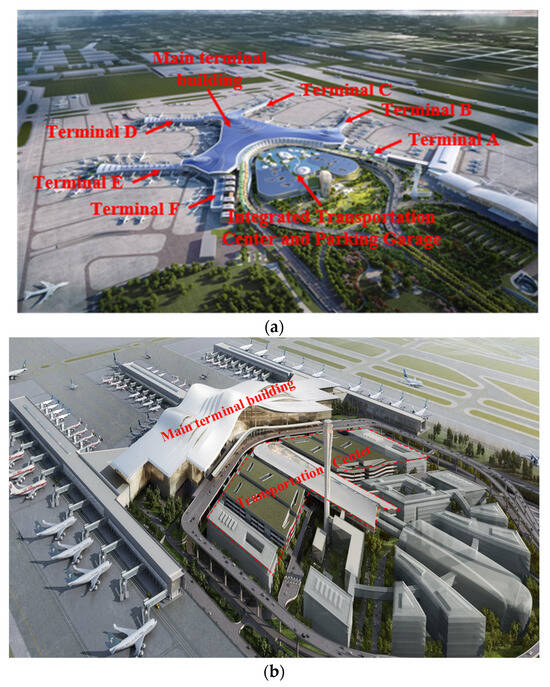
Figure 2.
Aerial view of the airport. (a) Jinan Yaoqiang International Airport, (b) Urumqi Tianshan International Airport.
As shown in Figure 2b, Urumqi Tianshan International Airport is located in the Dabancheng wind zone, one of the nine major wind zones in Xinjiang, where the basic wind pressure for a 50-year return period reaches 0.6 kPa, classifying the area as a strong-wind region. The terminal complex employs a large-span spatial structural system consisting of four principal modules: the main functional zone, the transportation center, the concourse cluster, and supporting service facilities. The transportation center integrates north–south multi-level parking structures with a three-dimensional intermodal transit hub, thereby enabling an efficient multimodal transport system and playing a critical role in passenger transfer operations. The roof system for this complex utilizes the standing seam Al-Zn-plated steel panels shown in Figure 1c.
3. Determination of Random Parameters for the Roof System
3.1. Determination of Random Parameters for the Al-Mg-Mn Roof System
3.1.1. Determination of Random Parameters for Wind Load
For standing seam metal roof systems, the principal sources of sample randomness arise from the volatility of material performance parameters, subjective uncertainties during panel installation, and the inherent variability of wind loads.
Regarding the stochastic nature of wind loads, the Al-Mg-Mn roof system investigated in this study is located in a region with the terrain roughness category B and with a structural height of 43.8 m. For long-span cladding structures, such as standing seam metal roofs, the load design code [20] specifies that the characteristic value of the wind load should be calculated using the following equation:
In Equation (1), βgz denotes the gust factor at height z; μz represents the wind pressure height variation coefficient; ωOR denotes the basic wind pressure, which, for long-span metal roof structures sensitive to wind loads, is calculated based on a 50-year return period with a value of 0.45 kPa; and μsl refers to the local shape coefficient, which depends on the building’s geometry and is determined through wind tunnel testing.
The wind tunnel test model of the Jinan Yaoqiang International Airport Terminal is illustrated in Figure 3. In accordance with the requirements for wind tunnel blockage ratio, turntable dimensions, and the prototype’s actual size, a geometric scale ratio of 1:250 was adopted for the model. A total of 1102 measurement points were arranged, with wind direction angles set at 10° intervals, resulting in 36 wind directions. The model faithfully replicated the architectural geometry based on the construction drawings, thereby capturing the influence of the building’s form on the distribution of surface wind pressure.
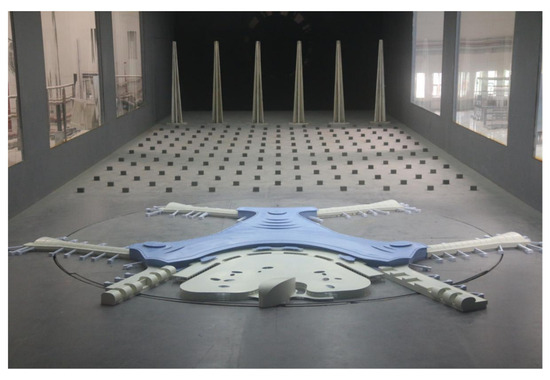
Figure 3.
Wind tunnel test model of Jinan Yaoqiang International Airport Terminal building.
Compression pressure was defined as the positive pressure direction. Based on the wind tunnel test results and Equation (1), the most unfavorable standard value of the wind load for a 50-year return period was determined to be 1.60 kPa. Referring to the statistical parameters of random variables reported in [22,23], the wind load was found to follow a Type I Extreme Value Distribution. The mean wind load was taken as 0.999 times the standard value, with a coefficient of variation of 0.193. Consequently, the mean wind load was calculated as μw = 1.60 × 0.999 = 1.598 kPa.
3.1.2. Determination of Structural Random Parameters
To account for the variability in material properties, this study considers the elastic modulus, yield strength, ultimate strength, and Poisson’s ratio as the random variables for the roofing system. The mean values of these parameters were obtained through tensile tests on the roof panels, while their probability distributions and statistical parameters were adopted based on the values reported in references [24,25]. Regarding the subjective uncertainties of the roof panels, it is recognized that manual seaming during installation may introduce variability in the tightness of the seams due to human factors. To capture this effect, the friction coefficient (μ) between the support and the roof panel was introduced as an additional random variable representing the influence of human factors, with its statistical parameters derived from the relevant literature.
Based on the above analysis, the probability distribution information of the random variables for the Al-Mg-Mn roof system is summarized in Table 1.

Table 1.
The probability distribution information of the random variables for the Al-Mg-Mn roof system.
3.2. Determination of Random Parameters for the Al-Zn-Plated Steel Roof System
3.2.1. Determination of Wind Load Random Parameters
The methodology for determining the stochastic characteristics of wind loads acting on the Al-Zn-plated steel roof system is essentially consistent with that adopted for the Al-Mg-Mn roof system, with both being calculated using Equation (1). The wind load shape coefficient μsl was likewise obtained from the wind tunnel test. The experimental model was a rigid body structure fabricated from acrylic panels and ABS sheets, as illustrated in Figure 4.
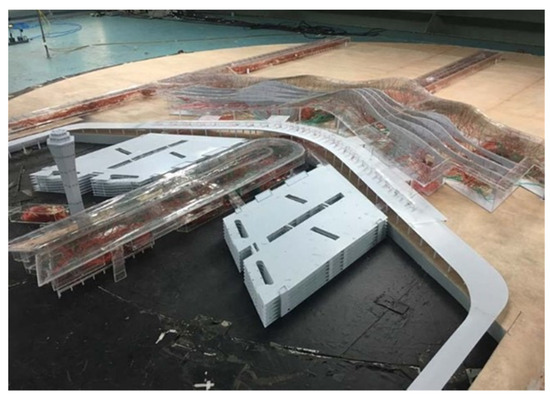
Figure 4.
Wind tunnel test model of Urumqi Tianshan International Airport.
Based on the wind tunnel test results and in conjunction with Equation (3), the most unfavorable standard value of wind load for the transportation hub under a 50-year return period was determined to be 2.72 kPa. The corresponding mean wind load was calculated as μw = 2.72 × 0.999 = 2.717 kPa.
3.2.2. Determination of Structural Random Parameters
Following the methodology adopted for the Al-Mg-Mn roof system, and incorporating data from the monotonic tensile test [26], the random variable parameters and their corresponding probability distributions for the Al-Zn-plated steel roof system are presented in Table 2.
Table 2.
The probability distribution information of the random variables for the Al-Zn-plated steel roof system.
4. Establishment and Validation of the Finite Element Model for the Roof System
4.1. Overview of Wind Uplift Test on Roof System
4.1.1. Overview of Static Wind Uplift Test on Al-Mg-Mn Roof System
Extensive research has been conducted on the static wind uplift test for this type of roof system, with relevant experimental data and conclusions to be found in the work of Li at Tianjin University [27]. In these tests, disengagement failure occurred at a load of 1.76 kPa. The roof panel conditions and corresponding loading values during the test are presented in Table 3.
Table 3.
Details of damage to Al-Mg-Mn roof panels.
4.1.2. Overview of Static and Dynamic Wind Uplift Test on Al-Zn-Plated Steel Roof System
The wind uplift test for the Al-Zn-plated steel roof system of Urumqi Tianshan International Airport was carried out at a testing facility in Urumqi. The installation and testing setup for the metal roof system included the sequential processes of installing purlins, mounting fixed supports, placing roof panels, seaming the panel edges, installing anti-wind clips, and arranging sensors and data acquisition systems, as illustrated in Figure 5a. The installation of displacement meters and strain gauges is shown in Figure 5b. The displacement transducer employed was a spring-return linear displacement gauge with a measurement range of 200 mm, as illustrated in Figure 5c. The strain gauges used were of type BX120-4AA, with a grid length of 4 mm and a grid width of 2 mm, providing a measurement range of 20,000 µε.
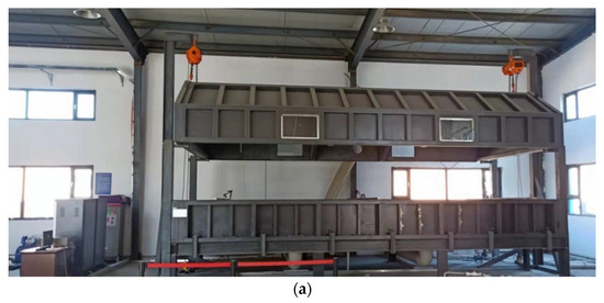
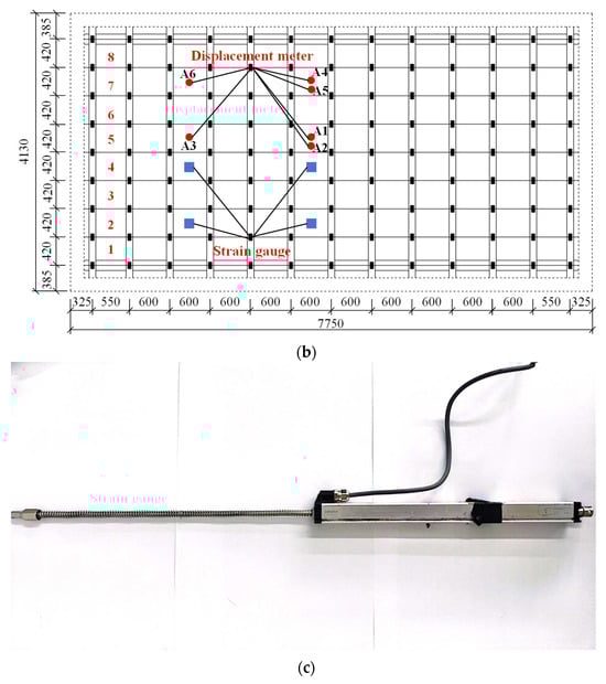
Figure 5.
Wind uplift test loading device and measurement point layout. (a) Loading device. (b) Displacement and strain measurement point layout diagram (unit: mm). (c) Spring-return linear displacement gauge.
According to the load scheme stipulated in Chinese GB 50205 [28], the loading protocol for the Al-Zn-plated steel roof system was classified into dynamic and static loading modes, which differs fundamentally from the purely static wind uplift loading scheme used for the Al-Zn-plated steel roof system. As shown in Table 4, in the dynamic loading mode, one cycle comprised five loading stages, with each stage grouped into two categories based on variations in wind pressure values, and each category containing four distinct loading sequences. If the specimen did not fail under cyclic dynamic loading, a static ultimate loading test was subsequently applied until failure occurred, thereby determining the maximum load-carrying capacity; the static loading sequence is shown in Figure 6. Based on the wind tunnel test results, and incorporating the dynamic wind load amplification effect into the most unfavorable calculated standard value, the design wind load for testing was determined to be −4.45 kPa.
Table 4.
Dynamic loading scheme: stage-by-stage loading ratios and number of cycles.

Figure 6.
Static loading sequence.
After 5000 loading cycles, the roof panels exhibited minor but irreversible deformation, while the roof system as a whole remained undamaged. During dynamic cyclic loading, displacements remained relatively small before reaching 50% of the target load, but increased rapidly thereafter. The maximum displacement of 150 mm was recorded at mid-span, with approximately 110 mm at the quarter-span location and 72 mm at the mid-span of the edge span. To determine the ultimate load-carrying capacity of the specimen, static loading was continued after the cyclic test. The structure remained intact under a load of 5.6 kPa; however, at approximately 5.7 kPa, noticeable bulging occurred at the seventh span, accompanied by disengagement of the fixed supports. The mid-span displacement of the roof panel abruptly increased from 155 mm to 170 mm, indicating the structural failure of the roof system. The deformation pattern of the roof panels during the ultimate loading test is illustrated in Figure 7.
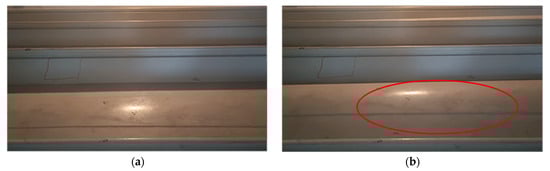

Figure 7.
Static loading deformation process of Al-Zn-plated steel roof panels (deformed areas indicated by red ovals). (a) The roof is initially in a state of no deformation. (b) The roof is slightly bulging and deformed. (c) The roof is severely bulging and significantly deformed. (d) The roof is in a state of extreme deformation.
4.1.3. Cyclic Loading Test of Al-Zn-Plated Steel Roof Panels and Results
The cyclic loading test was conducted in accordance with the test code [29]. The specimens were prepared from 0.8 mm-thick Al-Zn-plated steel roof panels used in the Transportation Center project. Following the specifications, P1-type rectangular proportional specimens with a gauge length of 15 mm were selected. The detailed specimen dimensions and the actual samples are shown in Figure 8.
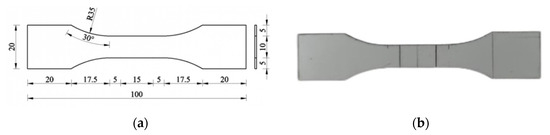
Figure 8.
Specimen overview. (a) Specimen dimensions (unit: mm). (b) Actual samples.
A total of twelve test groups were conducted, encompassing ten distinct load application procedures (with H1 repeated three times to verify the reliability of the experimental system). The primary objective was to investigate the effects of displacement amplitude and its incremental variation on the fatigue performance of roof panels subjected to tensile-dominated negative wind pressure. The specific load application procedures are illustrated in Figure 9.


Figure 9.
Loading sequence for each operating condition. (a) Displacement amplitude is 0.5 mm. (b) Displacement amplitude is 1.0 mm. (c) Displacement amplitude is 1.5 mm. (d) Displacement amplitude is 2.0 mm. (e) Displacement amplitude is 3.0 mm. (f) Initial displacement is 0 mm, increment is 0.1 mm. (g) Initial displacement is 0.1 mm, increment is 0.1 mm. (h) Initial displacement is 0.5 mm, increment is 0.1 mm. (i) Initial displacement is 0.1 mm, increment is 1.1 mm. (j) Initial displacement is 0.5 mm, increment is 1.0 mm.
The load–displacement curves of the specimens under different cyclic load application procedures are compiled and presented in Figure 10.
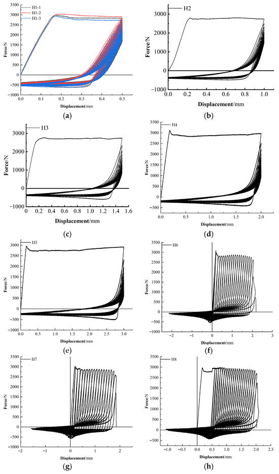

Figure 10.
Test curves for each cyclic load application procedure. (a) H1, (b) H2, (c) H3, (d) H4, (e) H5, (f) H6, (g) H7, (h) H8, (i) H9, (j) H10.
Based on the ductile damage model for metallic materials available in the ABAQUS material library, the damage variable D correlates with the fracture plastic displacement and equivalent plastic displacement . By fitting ten load application procedures, the expression for the damage variable D is obtained as follows.
4.2. Establishment of the Finite Element Model
Following the two aforementioned wind uplift tests, finite element models of two roof systems—the standing seam Al-Mg-Mn roof system and the standing seam Al-Zn-plated steel roof system—were developed in ABAQUS. For the Al-Mg-Mn roof system, the panel width was 400 mm, the thickness 0.9 mm, and the spacing between fixed supports 1200 mm; the diameter of end interlocking was 18 mm. For the Al-Zn-plated steel roof system, the panel width was 420 mm, the thickness 0.8 mm, the fixed supports spacing 1200 mm, and the diameter of end interlocking was 17 mm. For both types of roof systems, four-node doubly curved shell elements (S4R) were employed to model the roof panels, while eight-node hexahedral solid elements (C3D8R) were used to simulate the supports. The constitutive behavior of Al-Mn-Mg roof panels has been extensively investigated; therefore, a simplified bilinear ideal elastic–plastic model with linear hardening was adopted [24,25]. As illustrated in Figure 11a, the aluminum alloy panel with a thickness of 0.9 mm exhibits a yield strength of 191 MPa, an ultimate strength of 267 MPa, an elastic modulus of 67,810 MPa, and a density of 2.7 × 10⁻⁹ t/mm3. For the Al-Zn-plated steel roof panels, the constitutive relationship was derived from uniaxial tensile tests. As shown in Figure 11b, the 0.8 mm-thick steel panel demonstrates a yield strength of 345 MPa, an ultimate strength of 382 MPa, an elastic modulus of 206,854 MPa, and a Poisson’s ratio of 0.3. The experimentally measured density of the material was 7.75 × 10⁻⁹ t/mm3.

Figure 11.
Constitutive relationship of roof panel materials. (a) Al-Mg-Mn roof material. (b) Al-Zn-plated steel roof material.
As illustrated in Figure 12a,b, a mesh size of 2 mm was applied to the roof panel lock edges and the fixed supports, while the remaining roof panel regions were meshed with a size of 10 mm to improve computational efficiency. The resulting mesh was relatively uniform, free from significant distortion, and demonstrated overall good quality. Figure 12c,d show the three principal boundary conditions considered: (i) at the base of the supports, (ii) at the contact interfaces between the supports and the roof panels, and (iii) at the outer edges of the roof panels. For the Al-Mg-Mn roof system, the loading scheme was consistent with the static wind uplift test, with uniform pressure increments of 0.185 kPa applied stepwise until failure, and each load level was controlled through an analysis step schedule. For the Al-Zn-plated steel roof system, the static loading scheme was aligned with the ultimate static loading test, applying uniform increments of 0.7 kPa stepwise until failure, with load levels similarly managed through the analysis step schedule. To further enhance computational efficiency, this study adopted the equivalent cyclic load sequence based on the rain flow counting method proposed in [30,31,32] for the dynamic wind uplift simulation. This approach transforms low-ratio cyclic loads into a limited number of high-ratio cyclic load sequences with varying means and amplitudes, thereby significantly reducing simulation time while maintaining result accuracy.
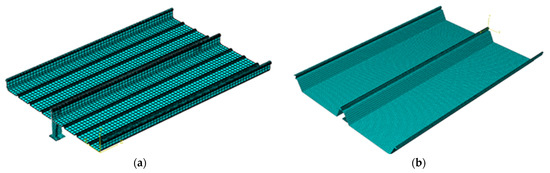

Figure 12.
Al-Mg-Mn roof and Al-Zn-plated steel roof grid and boundary condition settings. (a) Al-Mg-Mn roof model overall grid. (b) Al-Zn-plated steel roof model overall grid. (c) Al-Mg-Mn roof model boundary condition settings. (d) Al-Zn-plated steel roof model boundary condition settings.
4.3. Validation of the Finite Element Models
4.3.1. Validation of the Al-Mg-Mn Roof Finite Element Model
For the Al-Mg-Mn roof system, a mesh sensitivity analysis was conducted using four mesh configurations: coarse mesh (10 mm at the panel lock seam and supports, 20 mm elsewhere), medium mesh (5 mm at the lock seam and supports, 15 mm elsewhere), fine mesh (2 mm at the lock seam and supports, 10 mm elsewhere), and ultra-fine mesh (1 mm at the lock seam and supports, 5 mm elsewhere). For each mesh model, identical boundary conditions, loads, and contact relationships were applied in ABAQUS. The results indicate that the fine mesh provides failure loads consistent with experimental observations, with a displacement error of only 1.11%, while also maintaining high computational efficiency. The comparison between the mid-span displacement values obtained from the numerical simulation of the Al-Mg-Mn roof system and the wind uplift test is presented in Figure 13. The simulation results show excellent agreement with the experimental data, with minimal displacement error at the point of roof panel disengagement failure. The experimentally measured failure displacement was 86.1 mm, whereas the model predicted 85.1 mm, resulting in a negligible difference of 1.0 mm. Under an uplift failure load of 1.67 kPa, the experimental displacement was 80.2 mm, and the simulated displacement was 79.7 mm, indicating a similarly minor discrepancy. Therefore, the accuracy of the finite element model meets the requirements of this study.
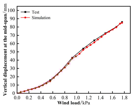
Figure 13.
Comparison of simulation results of Al-Mg-Mn roof model with wind uplift test results.
4.3.2. Validation of the Al-Zn-Plated Steel Roof Finite Element Model
For the Al-Zn-plated steel roof system, a mesh sensitivity analysis was conducted using four levels of discretization: coarse mesh (10 mm at the panel lock seam and supports, 20 mm elsewhere), medium mesh (5 mm at the lock seam and supports, 15 mm elsewhere), fine mesh (2 mm at the lock seam and supports, 10 mm elsewhere), and ultra-fine mesh (1 mm at the lock seam and supports, 5 mm elsewhere). Comparative analysis of these four mesh schemes revealed that the fine mesh provided results consistent with experimental observations, with a deviation of only 5.26% in failure displacement under cyclic loading. The discrepancy in ultimate load-bearing capacity and corresponding failure displacement was 7.67%. Moreover, the fine mesh demonstrated superior computational efficiency, making it the most suitable choice for numerical simulation.
As shown in Figure 14a, the numerical simulation closely matches the experimental data, with displacement variation trends fundamentally consistent between the two. At a loading ratio of 100%, the deviation in mid-span displacement between simulation and experiment is approximately 4 mm, demonstrating the high accuracy of the model. For the ultimate loading process, mid-span displacement was also used for validation, as depicted in Figure 14b. Experimental results indicate that the roof system experienced disengagement failure at a load of 5.7 kPa, accompanied by a sudden displacement increase to 168 mm. The simulation predicted the onset of initial disengagement at 5.4 kPa (displacement of 155.1 mm), with a difference of only 13 mm from the experimental failure displacement.

Figure 14.
Comparison of simulation results of Al-Zn-plated steel roof model with wind uplift test results. (a) Comparison between cyclic loading test and simulation. (b) Comparison between ultimate loading test and simulation.
The relatively large simulation error observed in the Al-Zn-plated steel roof system primarily arises from the plastic deformation induced in the roof panels under high-intensity cyclic loading. Since the numerical analysis employed a simplified constitutive model, the yielding phase of the material was represented, but the post-yield nonlinear behavior was not adequately captured. Consequently, discrepancies in panel displacement emerged, with greater deviations occurring in the ultimate loading stage, as this phase was conducted after cyclic loading. Nevertheless, the overall simulation results demonstrate satisfactory agreement with experimental observations and are considered reliable for subsequent analytical studies.
5. Establishment of Limit State Function of Roof Systems
5.1. Numerical Simulation Analysis of Roof System Under Different Scenarios
To define the limit state function of the Al-Mg-Mn roof system and the Al-Zn-plated steel roof system, a parametric study was conducted using the controlled variable method. Four parameters—roof panel width, roof panel thickness, fixed support spacing, and the diameter of end interlocking of the roof panel—were individually varied, establishing 30 simulation scenarios for detailed analysis. The specific parameters are listed in Table 5 and Table 6.
Table 5.
Numerical simulation of Al-Mg-Mn roof system operating scenarios.
Table 6.
Numerical simulation of Al-Zn-plated steel roof system operating scenarios.
Among these, scenarios Y1–Y16 and W1–W16, respectively, examine the influence of roof panel width and fixed support spacing on the wind load resistance capacity of the two types of roof panels. Scenarios Y1, Y3, and Y17–Y22 and W1, W3, and W17–W22 investigate the effect of roof panel thickness on the wind resistance of both roof systems. Scenarios Y1, Y3, and Y23–Y30 and W1, W3, and W23–W30 assess the impact of the diameter of the roof panel’s end interlocking on their wind load resistance capacity. Figure 15 presents the curves of the mid-span displacement of the roof panels as a function of wind load under the 30 finite element simulation scenarios. The wind load-bearing capacity of the roof system under various scenarios and the mid-span failure displacement values are shown in Table 7.

Figure 15.
Load-to-midspan vertical displacement curve of roof systems under different operating scenarios. (a) Standing seam Al-Mg-Mn roof system. (b) Standing seam Al-Zn-plated steel roof system.
Table 7.
Failure loads and failure displacement values for two types of roof systems.
Under 30 simulated load scenarios for each of the two types of roof systems, the roof panels exhibited detachment failure characterized by the panels disengaging entirely from their fixed supports, as illustrated in Figure 16. Notably, the vertical displacement at the mid-span on the large-eave side was significantly greater than that on the small-eave side, with the large-eave panels preferentially experiencing detachment in a sudden failure process. As shown in Figure 15 and Table 7, the failure displacement values of the Al-Mg-Mn roof system ranged from 66 mm to 159 mm, corresponding to failure loads between 1.345 kPa and 2.89 kPa. For the Al-Zn-plated steel roof system, the mid-span vertical displacement at failure varied from 113 mm to 223 mm, with corresponding failure loads ranging from 3.53 kPa to 11.12 kPa. The substantial differences in wind load resistance capacity between these two roof systems are attributed to the combined effects of variations in panel materials, structural parameters, support types, and interlocking mechanisms. Nevertheless, the trend of mid-span vertical displacement variation under different loading scenarios remained consistent for both systems, indicating that mid-span vertical displacement can serve as a reliable metric for assessing roof system failure. Consequently, by eliminating the influence of structural parameters, a unified failure criterion can be established to evaluate damage across different roof systems.
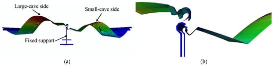
Figure 16.
Numerical simulation of roof system failure conditions. (a) Overall damage. (b) Connection damage.
5.2. Determination of Failure Criteria
To further summarize the wind-induced failure patterns of the roof system arising from the variations in structural parameters and to establish a unified metric for assessing the failure state of the roof panels, the mid-span vertical displacements at failure under various scenarios for two types of roof systems were compiled, as shown in Figure 17a–h. The effects of panel width, support spacing, panel thickness, and end interlocking diameter on mid-span vertical displacement were systematically investigated.
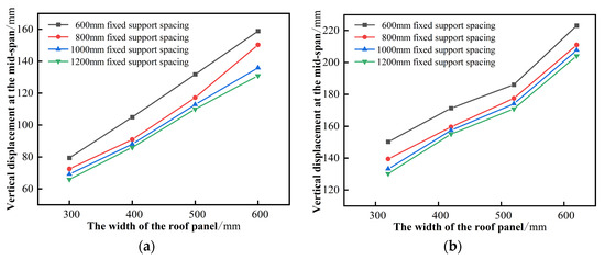

Figure 17.
The effect of different structural parameters on the vertical displacement at the mid-span of two types of roof systems. (a) The effect of the width of Al–Mg–Mn roof panels. (b) The effect of the width of Al-Zn-plated steel roof panels. (c) The effect of the spacing between Al–Mg–Mn roof fixed supports. (d) The effect of the spacing between Al-Zn-plated steel roof fixed supports. (e) The effect of Al–Mg–Mn roof panel thickness. (f) The effect of Al-Zn-plated steel roof panel thickness. (g) The effect of the diameter of the Al–Mg–Mn roof end interlocking. (h) The effect of the diameter of the Al-Zn-plated steel roof end interlocking.
As illustrated in Figure 17a–h, the relationships between panel width, panel thickness, and end interlocking diameter with mid-span vertical displacement exhibit linear characteristics, whereas support spacing displays a nonlinear relationship with the mid-span vertical displacement. Specifically, the mid-span vertical displacement is positively correlated with panel width and end interlocking diameter, and negatively correlated with support spacing and panel thickness.
Based on reference [33], a finite element model of the standing seam Al–Mg–Mn roof system under multiple loading conditions was established using ANSYS 14.5. The effects of roof panel width and support spacing on the system’s wind load resistance capacity were analyzed, leading to the determination of the roof panel failure criterion. Building on this study, the present work develops a unified failure index expression characterizing both the Al–Mg–Mn roof system and the Al-Zn-plated steel roof system by incorporating multiple parameters: roof panel width, support spacing, panel thickness, and end interlocking diameter. The formula is given in Equation (3):
In Equation (3), L denotes the support spacing; L0 is the reference spacing for dimensional normalization, set to 10 mm; h represents the mid-span vertical displacement; t is the roof panel thickness; W is the roof panel width; and d is the end interlocking diameter. All variables are expressed in millimeters. The coefficient α is a constant determined by extracting the mid-span displacement of the roof panel at failure under various scenarios, along with the corresponding roof panel width, spacing between fixed supports, panel thickness, and end interlocking diameter. Following the method described in reference [33], α was obtained through optimization and standardized fitting, with the objective of minimizing the standard deviation. The Generalized Reduced Gradient (GRG) nonlinear algorithm was employed for the solution, with α set as the variable cell and without imposing additional constraints. In this study, α is taken as 9.03 for the Al–Mg–Mn roof system and 5.71 for the Al-Zn-plated steel roof system, with corresponding standard deviations of 0.08 and 0.12, respectively.
A comprehensive computational analysis of the damage index curves under various loading scenarios for both roof systems is presented in Figure 18. Comparison with Figure 15 reveals that, under different scenarios, the mid-span vertical displacements and corresponding failure loads at system failure vary greatly and exhibit considerable dispersion. However, the damage index η of both roof systems remains nearly consistent across different scenarios, stabilizing close to 1.0 at structural failure, indicating low variability. This demonstrates the feasibility of establishing failure criteria for different types of standing seam metal roof systems by introducing a damage index, thereby enabling wind-uplifted resistance reliability analysis. Accordingly, η0 = 1.0 is defined as the threshold indicating failure onset for both the Al–Mg–Mn roof system and the Al-Zn-plated steel roof system.

Figure 18.
Load–damage index curve of roof systems under different operating scenarios. (a) Standing seam Al-Mg-Mn roof system. (b) Standing seam Al-Zn-plated steel roof system.
5.3. Determination of the Performance Limit State Function
Through the above research, the limit state function of the standing seam Al–Mg–Mn and Al-Zn-plated steel roof systems are established as follows:
In the equations, η0 represents the failure threshold for the Al–Mg–Mn and Al-Zn-plated steel roof systems, both set to 1.0. η denotes the damage index under various load scenarios for these roof systems, which is determined by the response values of sample points obtained through random variable sampling as detailed in Table 1 and Table 2, respectively.
6. Reliability Assessment of Roof System Wind-Uplifted Resistance
6.1. Reliability Results of Roof System Wind-Uplifted Resistance
Based on the reliability analysis methodology presented in reference [34], the failure probability Pf and reliability index β of the Al-Mg-Mn roof system and the Al-Zn-plated steel roof system are calculated as follows:
In the equation, I takes the value of 1 or 0, and Ωm represents the m-th simulated sample point; G(Ωm) denotes the response value corresponding to the m-th sample.
A MATLAB R2023b code implementing the LHS–MCS method was developed to extract 103 sets of random samples for both the Al-Mg-Mn roof system and the Al-Zn-plated steel roof system to perform the wind-uplifted resistance reliability analysis. The performance function values for each sample point of the roof systems were obtained via Equation (4), while the failure probability Pf and reliability index β under wind loads for the roof systems were calculated using Equation (5). The results are presented in Table 8 and Table 9. Following the procedure in reference [34], a conventional Monte Carlo Simulation (MCS) code was also developed, which extracted 105 sample points for both roof systems to compute the failure probabilities and reliability indices. These results, serving as benchmark solutions, are also included in the tables.
Table 8.
Calculation results for the reliability of Al-Mg-Mn roof system under wind loads.
Table 9.
Calculation results for the reliability of Al-Zn-plated steel roof system under wind loads.
As shown in Table 8 and Table 9, the errors of the reliability indices obtained by the LHS–MCS method relative to those obtained by the MCS method for the Al-Mg-Mn and Al-Zn-plated steel roof systems are 1.09% and 1.50%, respectively. Notably, the number of simulations conducted by LHS–MCS is only 1% of that used in MCS. Therefore, the LHS–MCS-based approach enables efficient and accurate reliability analysis of wind-uplifted resistance for both types of roof systems.
Figure 19 illustrates the sample points and corresponding performance function values obtained via the LHS–MCS method for the two roof systems, while Figure 20 depicts the cumulative distribution functions (CDFs) and probability density functions (PDFs) of the performance function values. Combined observations from Figure 19 and Figure 20 show that the performance function values for both roof systems predominantly range between 0.35 and 0.60, with a minority of samples falling into the failure domain between −0.1 and 0. The CDF and PDF curves exhibit highly similar and smooth distributions, confirming the effectiveness of the LHS–MCS method in conducting reliability analyses of wind-uplifted resistance for standing seam metal roof systems.
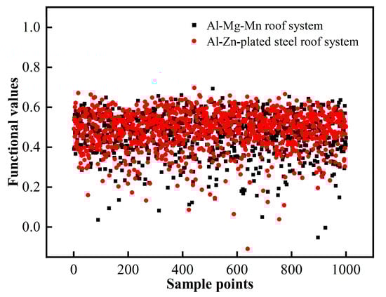
Figure 19.
Roof system sample points and functional values.
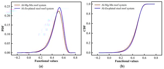
Figure 20.
Probability density functions and cumulative distribution functions of roof systems. (a) PDF. (b) CDF.
6.2. Evaluation of the Safety Level of the Roof System
The unified standard for reliability design [21] classifies structural safety levels into Level I, Level II, and Level III based on the severity of structural failure, and specifies the minimum reliability index β values for each safety level under ultimate limit states, as presented in Table 10. For critical structures such as Jinan Yaoqiang International Airport and Urumqi Tianshan International Airport, which are designated as Level I safety, the failure form is ductile failure, and the β value should not be less than 3.7. In this study, however, the reliability index β for the Al-Mg-Mn roof system is only 3.0975, and for the Al-Zn-plated steel roof system, it is 3.2850—both below the code requirements—indicating potential safety risks under extreme wind loads. Therefore, it is recommended to reinforce the connections between the roof panels and supports as well as wind-sensitive areas. Measures may include reducing the spacing of the fixed support, decreasing the width of the roof panel, increasing the thickness of the roof panel, and reducing the end interlocking diameter, thereby enhancing the wind load resistance capacity of the roof system.
Table 10.
Reliability index requirements for structural components in the standard.
7. Influence of Roof System Structural Parameters on Wind-Uplifted Resistance Reliability
7.1. Determination of Structural Parameters and Load Scenarios
To enhance the reliability indices of two types of roof systems under extreme wind loads and reduce the associated safety risks, this section employs the control variable method based on previous studies. Twenty sets of load scenarios from Table 5 and Table 6, namely Y1–Y12 and Y23–Y30, as well as W1–W12 and W23–W30, are selected. The effects of three structural parameters—roof panel width, support spacing, and end interlocking diameter of the roof panel—on the wind-uplifted resistance reliability of the two roof systems are systematically investigated.
7.2. Results of Parameter Analysis
Following the wind-uplifted resistance reliability analysis procedure outlined in Section 6.1, the limit state function, along with their corresponding cumulative distribution functions (CDFs) and probability density functions (PDFs) for the twenty samples of the Al-Mg-Mn roof system and the twenty samples of the Al-Zn-plated steel roof system, are presented in Figure 21. It is observed from Figure 21 that the limit state function values of the Al-Mg-Mn roof system are highly concentrated within the range of 0.32 to 0.63, with a small number of samples falling into the failure domain between −0.24 and 0. Conversely, the limit state function values for the Al-Zn-plated steel roof system are similarly concentrated between 0.36 and 0.61, with a few samples located within the failure domain from −0.26 to 0. The overall trends of the PDF and CDF curves for both roof systems exhibit strong similarity across the various load scenarios. However, the peak values and corresponding probabilities of the PDF curves, as well as the inflection points of the CDF curves, vary in response to changes in the structural parameters.
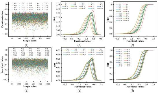
Figure 21.
Results of the limit state function of the roof systems under different structural parameters. (a) Sample points and functional values of Al–Mg–Mn roof system. (b) Probability density functions of Al–Mg–Mn roof system. (c) Cumulative distribution functions of Al–Mg–Mn roof system. (d) Sample points and functional values of Al-Zn-plated steel roof system. (e) Probability density functions of Al-Zn-plated steel roof system. (f) Cumulative distribution functions of Al-Zn-plated steel roof system.
Figure 22 presents the reliability analysis results of wind-uplifted resistance for two types of roof systems under various operating scenarios. In conjunction with the reliability index requirements detailed in Table 10, it is observed that scenarios Y23, Y24, Y26, W4–W8, and W24 satisfy the first-level safety requirement. Scenarios Y1, Y10, and Y11 and W11, W27, and W30 meet only the third-level safety requirement, while scenarios Y9, W9, W10, and W29 fail to meet the third-level safety requirement. The remaining 21 scenarios conform to the second-level safety requirement.
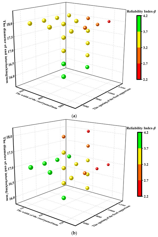
Figure 22.
Analysis results of the reliability of roof systems’ wind-uplifted resistance under different structural parameters. (a) Standing seam Al-Mg-Mn roof system. (b) Standing seam Al-Zn-plated steel roof system.
Therefore, to enhance the wind uplift capacity of the Al-Mg-Mn roof system, while keeping other parameters unchanged, reducing the end interlocking diameter at the connections between the roof panel and support to 16 mm is sufficient to achieve the first-level safety requirement, as exemplified by scenario Y23. When the end interlocking diameter is reduced to between 16 mm and 16.5 mm and the spacing of the fixed support is further decreased to 800 mm, the reliability index improves significantly, as shown in scenarios Y24 and Y26.
For the Al-Zn-plated steel roof system, the first-level safety requirement can be met either by decreasing the fixed support spacing to 600 mm or by simultaneously reducing the fixed support spacing to 800 mm and the end interlocking diameter to 16 mm, as demonstrated in scenarios W4 and W24. Additionally, narrowing the roof panel width to 320 mm can further enhance the reliability index, as indicated by scenarios W5–W8.
8. Conclusions
This study, drawing upon wind resistance tests, finite element simulations, and reliability analyses of wind-uplifted resistance, investigates the wind-resistant performance of two widely used standing seam metal roof systems. The key findings are summarized as follows.
- High-fidelity finite element models of the two roof systems were developed based on wind uplift and wind tunnel tests. Thirty operating scenarios were analyzed to evaluate the effects of panel width, support spacing, panel thickness, and end interlocking diameter on the wind uplift capacity. A unified failure indicator was established to quantify failure forms, and corresponding limit state functions were formulated.
- The LHS–MCS method was applied to conduct wind-uplifted resistance reliability analyses of the two typical standing seam metal roof systems, demonstrating their applicability. Compared to conventional Monte Carlo simulation, the LHS–MCS approach required only 1% of the simulation runs while maintaining calculation errors of 1.09% and 1.5%, indicating high accuracy and computational efficiency.
- The reliability indices for the standing seam Al–Mg–Mn and Al-Zn-plated steel roof systems obtained in this study were 3.0975 and 3.2850, respectively—both below the code-specified threshold of 3.7 for buildings of this safety class. This suggests potential safety risks under extreme wind loads. Considering practical design and construction conditions, it is recommended to prioritize reduction in support spacing or end interlocking diameter at panel–support connections and weak points to enhance structural safety and meet the first-level safety requirement.
Author Contributions
Conceptualization, R.Z. and L.W.; methodology, L.W. and Y.H.; software, Y.W. and L.W.; validation, L.W. and Y.H.; data curation, H.Z. and Y.W.; writing—original draft preparation, L.W.; writing—review and editing, R.Z.; supervision, R.Z. and H.Z.; project administration, H.Z.; funding acquisition, R.Z. All authors have read and agreed to the published version of the manuscript.
Funding
This research was funded by Key Research and Development Project in the Xinjiang Uygur Autonomous Region (Grant NO.2023B01023-1).
Data Availability Statement
The data presented in this study are available upon request from the corresponding author.
Conflicts of Interest
Author Huijun Zhao was employed by the company Xinjiang Construction Engineering Road & Bridge Engineering Co., Ltd., China. The author Yihao Wang was employed by the company China Shipbuilding NDRI Engineering Company Limited. Author Yifan He was employed by the company State Grid Xinjiang Electric Power Co., Ltd. Construction Branch, Urumqi, China. The remaining authors declare that the research was conducted in the absence of any commercial or financial relationships that could be construed as potential conflicts of interest.
References
- Liu, M.; Tong, C.H.; Nie, S.D.; Liang, Q.S.; Gu, S.T.; Yang, Q.S.; Chen, S.H.; Lin, Z.Y. An equivalent spring model for evaluating the wind-resistance capacity of low-vertical 360° standing seam metal cladding systems. J. Eng. Struct. 2025, 343, 121134. [Google Scholar] [CrossRef]
- Wu, B.; Zhao, H.; Chen, B.; Yang, Q.S. Comparison of wind-resistant capacities of standing seam roof systems under static uniform pressures and dynamic non-uniform wind pressures. J. Wind Eng. Ind. Aerodyn. 2023, 241, 104807. [Google Scholar] [CrossRef]
- Darwish, Y.; ElGawady, M. Finite element analysis of TPO membrane-retrofitted metal roof system subjected to wind loads. Structures 2023, 50, 330–346. [Google Scholar] [CrossRef]
- Azzi, Z.; Habte, F.; Vutukuru, S.K.; Arindam, G.C.; Moravej, M. Effects of roof geometric details on aerodynamic performance of standing seam metal-roofs. Eng. Struct. 2020, 225, 111303. [Google Scholar] [CrossRef]
- Tiwari, S.; Roy, K.; Fang, Z.Y.; Lim, J. Metal roof cladding system under wind-loading: State-of-the-art. J. Wind Eng. Ind. Aerodyn. 2025, 257, 105939. [Google Scholar] [CrossRef]
- Darwish, Y.; ElGawady, M.; Kirby, J.; Keegan, J. Experimental testing of full-scale retrofitted metal deck system under wind-uplift. Structures 2025, 75, 108722. [Google Scholar] [CrossRef]
- Zulfiqar, Y.; Zulfiqar, A.; Ahmad, H.W.; Chaudry, U.M.; Khan, M.K.; Jun, T.S. Detailed structural analysis of cylindrical steel tank subjected to various seismic peak ground values using FSI approach. Appl. Mech. 2023, 4, 990–1014. [Google Scholar] [CrossRef]
- İnam, İ.E.; Dindar, A.A. Deformation and energy-based comparison of outrigger locations in RC and BRB-core tall buildings under repetitive earthquakes. Buildings 2025, 15, 3563. [Google Scholar] [CrossRef]
- Nicola, L.; Pietro, C.; Marco, Z. The influence of the geometrical features on the seismic response of historical churches reinforced by different cross lam roof-solutions. J. Bull. Earthq. Eng. 2022, 20, 6813–6852. [Google Scholar] [CrossRef]
- Hu, J.J. Wind Fragility Analysis and Risk Assessment Method for Standing Seam Roof System Considering Fuzziness of Performance Level. Master’s Thesis, Chongqing University, Chongqing, China, 2023. (In Chinese). [Google Scholar]
- Rosowsky, D.V.; Cheng, N. Reliability of light-frame roofs in high-wind regions I: Wind loads. J. Struct. Eng. 1999, 125, 725–733. [Google Scholar] [CrossRef]
- Rosowsky, D.V.; Cheng, N. Reliability of light-frame roofs in high-wind regions II: Reliability analysis. J. Struct. Eng. 1999, 125, 734–739. [Google Scholar] [CrossRef]
- Shanmugam, B.; Nielson, B.G.; Prevatt, D.O. Statistical and analytical models for roof components in existing light-framed wood structures. J. Eng. Struct. 2009, 31, 2607–2616. [Google Scholar] [CrossRef]
- Yang, N.; Liu, W.; Bai, F.; Ge, H. Research on time-varying reliability of self-tapping screw joints of light-weight steel roofs under typhoon. J. Hunan Univ. 2021, 48, 72–81. (In Chinese) [Google Scholar]
- Li, Z.L.; Wang, C.; Wang, T.; Wang, Z.S.; Li, J.H. Reliability analysis of wind-resistance of standing seam roof system based on active learning kriging model. J. Eng. Mech. 2022, 39, 111–119. (In Chinese) [Google Scholar] [CrossRef]
- Li, Z.L.; Wang, C.; Wang, T. Reliability analysis of wind-uplifted resistance of standing seam roof system with anti-wind clips. J. Harbin Inst. Technol. 2022, 54, 75–83. (In Chinese) [Google Scholar]
- Xia, Y.C.; Chen, S.F. Wind-induced damage processes of standing seam metal roof systems. J. Harbin Inst. Technol. 2021, 53, 136–141. (In Chinese) [Google Scholar]
- Habte, F.; Mooneghi, M.A.; Chowdhury, A.G.; Peter, I. Full-scale testing to evaluate the performance of standing seam metal roofs under simulated wind loading. J. Eng. Struct. 2015, 105, 231–248. [Google Scholar] [CrossRef]
- Wu, T. The Wind Uplift Failure Mechanism and Wind Vulnerability Analysis of Standing Seam Metal Roof Plate. Master’s Thesis, Harbin Institute of Technology, Harbin, China, 2022. (In Chinese). [Google Scholar]
- GB 50009-2012; Load Code for the Design of Building Structures. China Architecture & Building Press: Beijing, China, 2012.
- GB 50068-2018; Unified Standard for Reliability Design of Building Structures. China Architecture & Building Press: Beijing, China, 2018.
- Liu, H.L.; Gao, J.; Shao, X.Y. Reliability study based on new codes of lightweight steel structure. J. Build. Struct. 2010, 40, 77–82+76. (In Chinese) [Google Scholar]
- Dai, G.X.; Xia, Z.Z. Applicability analysis of building steel structure. J. Build. Struct. 2000, 21, 36–40. (In Chinese) [Google Scholar]
- Yu, Z.M. Resistant Performance of Standing Seam Metal Roof System Under Fluctuating Wind Uplift. Master’s Thesis, Harbin Institute of Technology, Harbin, China, 2019. (In Chinese). [Google Scholar]
- Lei, X.; Fu, X.; Xiao, K.; Wang, J.; Nie, M.; Li, H.N.; Xie, W.P. Failure analysis of a transmission tower subjected to wind load using uncertainty method. J. Proc. CSEE 2018, 38 (Suppl. S1), 266–274. (In Chinese) [Google Scholar]
- Wang, Y.H. Study on Influence of Detailed Structural Parameters of Standing Seam Roof System on Wind Resistance. Master’s Thesis, Xinjiang University, Urumqi, China, 2024. (In Chinese). [Google Scholar]
- Li, L.C. Study on the Wind Resistance of Large-Span Stadium Metal Roofing System. Master’s Thesis, Tianjin University, Tianjin, China, 2014. (In Chinese). [Google Scholar]
- GB 50205-2020; Code for Acceptance of Construction Quality of Steel Structure Engineering. China Planning Press: Beijing, China, 2020.
- GB/T 228.1-2021; Metallic Materials-Tensile Testing—Part 1: Method of Test at Room Temperature. State Administration for Market Regulation and National Standardization Administration of China: Beijing, China, 2021.
- Wu, T.; Sun, Y.; Cao, Z. Parameter determination of constitutive relationship of 3004H24 aluminum alloy based on ductile damage model. J. Struct. 2021, 34, 4447–4456. [Google Scholar] [CrossRef]
- Wu, T.; Sun, Y.; Cao, Z. A new recommended load cycle for dynamic wind-resistant test of roof system based on the principle of damage equivalence. J. Build. Eng. 2022, 48, 103911. [Google Scholar] [CrossRef]
- Wu, T.; Sun, Y.; Cao, Z.G.; Zhang, J. Wind vulnerability analysis of standing seam roof system considering fatigue damage. J. Thin-Walled Struct. 2023, 184, 110550. [Google Scholar] [CrossRef]
- Lv, H.B. Wind Disaster Vulnerability Study of the Standing Seam Metal Roof System. Master’s Thesis, Harbin Institute of Technology, Harbin, China, 2019. (In Chinese). [Google Scholar]
- Li, Z.L.; Wang, C.; Wang, T.; Fang, Z.Y. Reliability evaluation on wind-uplifted resistance of standing seam roof system under downburst. J. Hunan Univ. 2022, 49, 90–99. (In Chinese) [Google Scholar]


Disclaimer/Publisher’s Note: The statements, opinions and data contained in all publications are solely those of the individual author(s) and contributor(s) and not of MDPI and/or the editor(s). MDPI and/or the editor(s) disclaim responsibility for any injury to people or property resulting from any ideas, methods, instructions or products referred to in the content. |
© 2025 by the authors. Licensee MDPI, Basel, Switzerland. This article is an open access article distributed under the terms and conditions of the Creative Commons Attribution (CC BY) license (https://creativecommons.org/licenses/by/4.0/).