Abstract
In order to protect the boundary columns once tension region form on shear walls subjected to seismic loads, a new shear wall system constructed by partial-connected crossing-stiffened corrugated steel plate shear walls (PCCSWs) is proposed and investigated. Numerical modeling of the PCCSWs was conducted and validated by a similar test on single-span two-story corrugated steel plate shear wall test specimen. Some key parameters, such as material properties, height-to-thickness ratio, wave length, and width of the crossing stiffeners, were then investigated through parametric analyses, and the results of PCCSWs were compared to the results of other types of steel shear walls. And a theoretical mechanical model was developed for predicting the ultimate capacity of the PCCSWs taking basis of the parametric results. Several findings can be concluded: (1) The finite element method (FEM) simulates buckling modes and the buckling positions of corrugated steel plates and boundary columns precisely, with the errors of initial stiffness and ultimate shear resistance being less than 10%, which proves the feasibility of the FEM. (2) The optimal values on such key parameters were the height-to-thickness ratio of 510~680 at the center, wave lengths of 360~480 mm, and varying widths of crossing stiffeners which are 64.41~136.89. (3) The relative errors between the theoretical and the numerical results were within 14.17%, and most of the variations were less than 10%, indicating the effectiveness of the developed mechanical model.
1. Introduction
In light of high beginning stiffness, great flexibility, solid seismic resistance, as well as diminishing primary distortions, the steel plate shear wall (SPSW) has been broadly utilized as a horizontal power-opposing framework (LFRS) for medium or elevated structures [1,2,3,4]. Yet, the SPSW easily buckles and has a low capacity to dissipate energy. Additionally, it can create a tension field, resulting in reductions in shearing resistance and lateral stiffness [5,6,7,8].
Under cyclic loading, many scholars often adopt approaches of material enhancement or structural strengthening to address some existing damage problems of structures. Zhang et al. significantly improved the mechanical properties of a new type of enhanced structure by performing CFRP strengthening and UHPC enhancement on the structure [9]. Compared with the non-stiffened SPSW, the diagonal stiffener played a significant role in improving the capacity to dissipate energy, ultimate load-carrying capacity, early stiffness, and ductility [10]. Cheng et al. [11] proposed to reinforce the wall with CFRP to improve the buckling capacity of the shear wall structure and conducted experimental and numerical modeling studies. The results show that the use of CFRP can improve the performance of shear walls. Haddad et al. [12] conducted a study on both stiffened and non-stiffened SPSWs by means of cyclic loading and found that the stiffened SPSWs with cross-shaped stiffeners exhibited a notable enhancement in terms of ductility, energy dissipation capacity, and shear stiffness. Additionally, the quasi-static tests carried out by Mu et al. [13] on two single-span double-story specimens illustrated that the flexural and torsional stiffness of groove stiffeners were fully exploited, thereby significantly enhancing the structure’s load-carrying capacity, stiffness, and resistance to elastic buckling.
The corrugated steel plate shear walls (CSPWs) have attracted more attention compared to the traditional SPSW because the CSPW exhibits excellent ductility, energy dissipation capacity, and shear strength [14,15]. Vaziri et al. [16] carried out numerical analysis on 20 specimens of CSPWs with different geometric parameters, and the findings indicated that CSPWs possessed greater initial stiffness than SPSWs. Ghodratian et al. [17] carried out experimental and numerical investigations on the specimen of double CSPWs (DCSPWs), and results indicated that the DCSPW exhibits excellent load-carrying and energy-dissipating capacity. And Wen et al. [18] carried out numerical simulation and theoretical analysis on DCSPWs and obtained stability analysis curves as well as proposed a bearing capacity design formula under combined shear and compression loads. In addition, adjusting the size of corrugated plates can prevent elastic buckling [19,20,21]. As the height-to-width ratio, number of fastening bolts, and ripple amplitude increase, the ultimate shear resistance of the CSPW also increases. However, to prevent a significant drop in strength after buckling, it is necessary to choose reasonable geometric parameters [22,23,24,25,26]. Further, the tension field is generated by the corrugated steel plate’s linkage to the boundary column; hence, the boundary columns need to possess adequate strength to hold back the extra forces derived from such tension fields [27]. And the beam-only-connected SPSW was proposed to prevent high flexural movement in the boundary columns [28]. Afterwards, Hu et al. [29] investigated a fully precast double-layer CFST/moment resistant frame structure by means of cyclic tests and theoretical analysis. It clearly demonstrated that the beam-connected SPSWs increase the ductility and initial stiffness of these frames. And Nima Paslar et al. [30] conducted an accurate study on the connection between steel plate and boundary frame by establishing 57 calculation models, and the results revealed that the lateral load-carrying capacity of the structure was reduced significantly by the shear wall connected with the beam than that with the boundary column. The test of beam-only-connected SPSWs with composite columns was carried out by Guo et al. [31]. According to their findings, under cyclic loads, SPSWs with buckling-restrained infill plates demonstrated acceptable ductility and steady hysteretic responses.
Although the SPSW structure has been focused on in many experimental and theoretical investigations, the out-of-plane buckling still occurs at the early stage. Therefore, it is necessary to study the stiffened corrugated shear wall steel plate. The asymmetric diagonal stiffened beam-only-connected corrugated steel plate shear wall (ASW) has been proposed by our research group, and the seismic performance of ASW has also been investigated through the test-validated FEM [32]. In order to further investigate the lateral resistance of the stiffened CSPW, this research proposed a different stiffened CSPW called the beam-only-connected CSPW with crossing stiffeners, as shown in Figure 1. Within this design, the corrugated steel plate is connected to the beam by bolts, with the connection realized via intermittent angle steels or fishplates [33], and crossing stiffeners are provided in the corrugated steel plate. This configuration postpones the formation of tension fields and the general buckling of overall wall panels as early as during the early stages in the construction process. In addition, the direct effects demonstrated serve to mitigate out-of-plane buckling in the central area of the plate. As a result, the bearing capability of the beam-only-connected corrugated steel plate shear wall (BCSPW) is improved and the wall becomes more ductile and capable of energy dissipation during an earthquake. In this research, the finite element (FE) model was established and verified by using the 2022 version of ABAQUS software. We investigate the cyclic performance of the PCCSW and estimate whether certain parameters affect the behavior of the structure. Finally, there are commercial vehicle shear resistance formula stakeholders that can be obtained from the computational model. Theoretically derived results are subsequently compared against those obtained from FE analysis, so as to verify the validity of the formula.
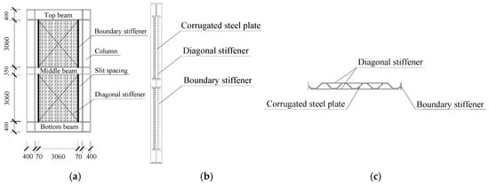
Figure 1.
Dimension details of PCCSW specimen: (a) PCCSW; (b) side view of PCCSW; (c) elevation view of PCCSW.
2. Numerical Modeling
2.1. Model Description
A single-span double-story PCCSW is selected from a CSPW structure; Figure 1 displays the dimensions of the PCCSW specimen. The column section is H 400 × 400 × 20 × 22 (section height × flange width × web thickness × flange thickness). The bottom-beam and top-beam portions are the same size, H 400 × 300 × 16 × 18. For the middle beam, its dimensions are H 350 × 300 × 14 × 16. The PCCSW is simulated using ABAQUS software, as illustrated in Figure 2a. The CSPW is only coupled to the beam at angles. The boundary stiffeners are welded with CSPWs, while the crossing stiffeners are welded to their outside surface.
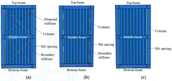
Figure 2.
FEM models: (a) PCCSW; (b) BSW; (c) USW.
To compare the seismic performance of the PCCSW to the BCSPW with boundary stiffeners (BSW) and the unstiffened BCSPW (USW), a BSW and an USW with the same sizes of boundary frames and CSPW are also modeled; these models are illustrated in Figure 2b,c.
These specimens all use vertical trapezoidal corrugated steel plates with a length and width of 3060 mm. The thickness is 4 mm and the slit spacing is 70 mm, as shown in Figure 1. The thickness of boundary stiffeners is 10 mm, and the width is 200 mm; the thickness of crossing stiffeners is 6 mm, and the width is 50 mm. The beam–column joints as well as column base joints use rigid connections. Table 1 displays the specific material properties of E235B steel (used for corrugated steel plates and crossing stiffeners) and E355B steel (used for beams, columns, column stiffeners, and boundary stiffeners).

Table 1.
Material properties of structural steel.
The stiffeners, corrugated steel plates, and boundary frame are all modeled numerically using S4R four-node shell components. Assuming that the steel is an ideal elastic–plastic material, and since a thin steel plate is used, the residual stress induced by welding is not considered. The component size of the frame is 40 mm × 40 mm. Based on mesh sensitivity analysis [34] and convergence analysis [35], and considering both computational accuracy and efficiency, 30 mm × 30 mm is selected as the size of the corrugated steel plate. To accurately and reliably simulate the failure mode and cyclic behavior of the specimen, L/750 of the maximum out-of-plane deformation of the corrugated steel plate is chosen as the initial imperfection and applied to the finite element model [35]. The weld connections in the beams, columns, column stiffeners, and corrugated steel plates are simulated using the “Merge” combination command. Corrugated steel plates are attached to the crossing stiffeners and boundary frames using the “TIE” instruction.
The vertical axial force is applied on the columns to simulate the gravity loads of structures; it is designed as 2000 kN according to the Chinese standard JGJ/99-2015 [36]. Cyclic stress is exerted on the center position of the top beam, while the loading scheme is formulated in line with the Chinese standard JGJ/99-2015 [36].
2.2. Validation of FEM
The finite element model of the PCCSW has not yet been validated by any cyclic experiments. Therefore, this study establishes a refined finite element model of the single-span double-layer CSPW specimen VCoSPSW-I [37] using the same modeling method. The corrugated steel plates and boundary frames are numerically modeled with S4R four-node shell elements. The welded connections among beams, columns, column stiffeners, and corrugated steel plates are simulated using the “merge” assembly command, while the corrugated steel plates are fixedly connected to the boundary frames via the “TIE” command. The same loading scheme is also adopted for the finite element analysis. Finally, it is subjected to comparative verification against the test results of VCoSPSW-1. The test specimen was designed with reduced size; the section size of the top beam and the bottom beam were the same, and they were H 250 × 200 × 12 × 14. The section of the middle beam was H 175 × 175 × 8 × 10, and middle-column section was H 200 × 200 × 8 × 12. The bolt-welded connection was utilized in beam–column joints, and the particulars of the specimen are introduced in Figure 3.
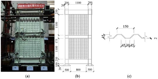
Figure 3.
Test specimen of VCoSPSW-I [36]: (a) model picture; (b) dimensions of model; (c) dimensions of steel plate.
The steel used in the boundary frame and CSPW was Q345 and Q235, respectively. The detailed material properties of specimen VCoSPSW-I are shown in Table 2.
Table 2.
Material properties of VCoSPSW-I [37].
Figure 4 compares the hysteretic and skeleton curves of FEM analysis and tests. Table 3 displays the specific findings. Throughout the loading process, the hysteretic curves of both the test and the finite element model exhibited a full spindle shape. In the later loading stage, the hysteretic curve of the test developed a pinching effect due to the occurrence of obvious out-of-plane deformation of the corrugated steel plate and local tearing of the steel plate. In contrast, the FE model adopted the assumptions of “no slippage or deformation at connections” and “steel as an ideal elastic–plastic material” (modeling settings in Section 2.1 of the manuscript), which prevented such damage and deformation from occurring. As a result, the FE model’s hysteretic curve remained fuller. And errors in initial stiffness and ultimate shear resistance are less than 10%.
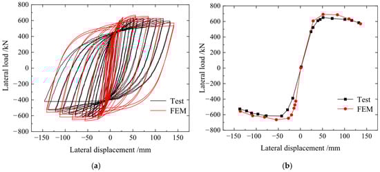
Figure 4.
The comparisons of FEM and test results of VCoSPSW-I: (a) hysteretic curves; (b) skeleton curves.
Table 3.
Detailed comparison results between the test and FEM.
At the final loading case, the column flanges and joints were seriously damaged. At the same time, the out-of-plane deformation in the corrugated steel plates was obvious, and some parts of the plates were torn. Figure 5 shows the comparison of failure modes between the test observations and finite element analysis. The finite element method simulates buckling modes and the buckling positions of corrugated steel plates and boundary columns precisely, verifying the reasonableness of the finite element model. It is obvious that the modeling method for the PCCSW in Section 2.1 is sensible, and the method can be utilized for parametric study.
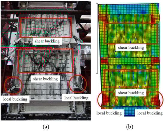
Figure 5.
Comparison of failure modes of test observation and FEM analysis: (a) test observation; (b) FEM analysis.
2.3. Comparative Analysis on Seismic Performance
Under cyclic loads, USW, BSW, and PCCSW FE studies are carried out. Figure 6 depicts the skeleton curves and hysteretic curves, while Table 4 displays the specific data.
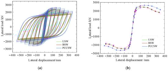
Figure 6.
Load–displacement curves of specimens: (a) hysteretic curves; (b) skeleton curves.
Table 4.
Characteristic results of specimens.
At the initial loading stage, there was little difference in the hysteresis loops among the three specimens. After yielding occurred, the energy-dissipating ability of specimen PCCSW was enhanced, with its hysteresis loop growing fuller. During late-stage loading, the steel plate in specimen USW experienced a bearing capacity decrease because of the overall buckling of specimens. In comparison, the bearing capacity of BSW declined earlier due to the out-of-plane buckling of its stiffeners. Notably, specimen PCCSW not only had a more gradual bearing capacity decrease but also exhibited superior ductility.
The maximum load of the PCCSW increased by 13% and 11% compared to the values of USW and BSW, respectively, and the ductility factor increased by 21% and 24%, respectively. Owing to the restraint of out-of-plane buckling deformation by the crossing stiffeners, both the area of the shear-flexural zone and the shear resistance of the PCCSW are increased.
The equivalent viscous damping coefficient he can be obtained by Equation (1):
where S(OBE+ODF) is the amount of the areas of ODF and OBE, and S(ABC+ACD) is the region of the hysteresis circle. The calculation diagram is shown in Figure 7.
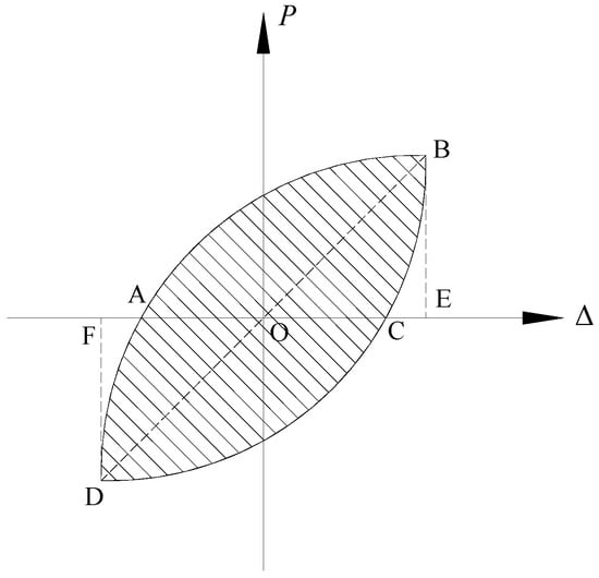
Figure 7.
The calculation diagram.
Figure 8a,b shows the energy dissipation capacity of the USW, BSW, and PCCSW. The total energy dissipation of the PCCSW increases by 23% and 20% compared to BSW and USW, respectively. The difference in total energy dissipation between USW and BSW is small. The results show that the boundary stiffeners had little effect on total energy dissipation of CSPW, but it is obviously increased by crossing stiffeners.
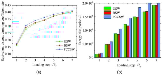
Figure 8.
Energy dissipation capacity of USW, BSW, and PCCSW: (a) equivalent viscous damping coefficients; (b) total energy dissipation.
3. Parametric Analyses of PCCSW
3.1. Design of Parameters
Table 5 lists some common parameters that were designed to illustrate how material strength, height–thickness ratio, wave length, and the width of crossing stiffeners influence the seismic performance of the PCCSW. There are four series and a sum of 19 examples in this review. The height of these corrugated steel plates is the same, and the height of the FEM specimen is 45 mm.
Table 5.
Details parameters of parametric analysis.
The same modeling technique described in Section 2.2 is used to create FEM models of these PCCSWs. The displacement-controlling loading scheme of this parametric study is shown in Figure 9. Before the yield displacement σy, the step loading with a 0.2σy interval was used, and each level of loading can require two cycles. When reaching the yield displacement σy, the step loading with a σy interval was used until the specimen was damaged, and each level of loading can require three cycles. The specimens in Table 5 share the same dimensions, material characteristics, boundary, and loading circumstances as the corrugated steel plate and boundary frame. In each series, just one parameter is altered; the others remain constant.
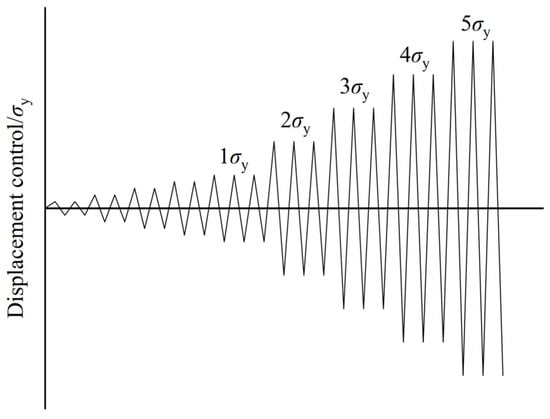
Figure 9.
The loading scheme.
3.2. Effects of Material Strength of PCCSW
There are four varieties of corrugated steel plates with varying material strengths, including LY100, LY160, LY225, and Q235. The stiffeners use Q235 steel for all the specimens in the PCCSW-M series. Table 6 shows the specific parameters of the PCCSW-M series.
Table 6.
Parameters of PCCSW-M series [35].
3.2.1. Analysis of Load–Displacement Curves
Figure 10 shows load–displacement curves of the PCCSW-M. With the buckling of the diagonal stiffener, the load-carrying capacity of the specimens diminished differently because of the different material strength of corrugated steel plates. Compared to M1, the ultimate resistance of M2, M3, and M4 increases by 19.8%, 31.3%, and 37.8%, respectively; and the initial stiffness increases by 7%, 7%, and 8%, respectively. The specimen’s ultimate displacement decreased successively with the increase in the strength of the corrugated steel plates, and the ductility coefficient of these specimens changed little. Due to efficient limitation of crossing stiffeners, the corrugated steel plates in these specimens reach their yield strength; thus, the lateral stiffness and ultimate resistance of the PCCSWs are increased by increasing the yield strength of corrugated steel plates.
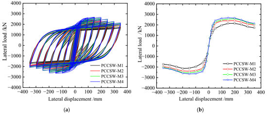
Figure 10.
Load–displacement curve of PCCSW-Ms: (a) hysteretic curves; (b) skeleton curves.
3.2.2. Analysis of Energy Dissipation
Figure 11 presents a comparison of energy dissipation capacity and the he for the PCCSW-M series. Compared to M1, the he of M2, M3, and M4 increases by 4.2%, 5.8%, and 7.4%, respectively; the energy dissipation of M2, M3, and M4 increases by 15%, 20%, and 25%, respectively. The low-yield-strength steel works in the earlier plastic stage, so the contribution of crossing stiffeners is not obvious for them. Therefore, under the condition with enough shear resistance, appropriately reducing the strength of the corrugated steel plate could enhance the specimen’s ability to bend plastically and dissipate energy, and the material could be fully used.
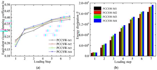
Figure 11.
Energy dissipation capacity of PCCSW-Ms: (a) he; (b) energy dissipation.
3.3. Effects of Height-to-Thickness Ratio of PCCSW
These SPSWs’ width and thickness can be altered to meet the steel boundary frame’s lateral stiffness and resistance requirements [38]. According to different height-to-thickness ratios, five types of corrugated steel plates are designed. Specific parameters of the PCCSW-T series are displayed in Table 7.
Table 7.
Parameters of specimens PCCSW-T.
3.3.1. Analysis of Load–Displacement Curves
Figure 12 shows the hysteresis loops for the PCCSW-Ts. The sample moves into the plastic stage earlier as the steel plate thickness increases and the stiffeners’ solidity proportion decreases. Compared to T1, the ultimate resistance of T2, T3, T4, and T5 increases by 9.41%, 13.41%, 29.38%, and 33.65%, respectively; the ductility decreases by 0.25%, 2.55%, 3.62%, and 4.82%, respectively; and the height-to-thickness proportion of the relating steel plate diminishes by 11.11%, 20.1%, 33.3%, and 38.5%, respectively. As the folded steel plate height-to-thickness proportion diminishes, the sidelong stiffness of the example improves steadily. However, there is less flexibility.
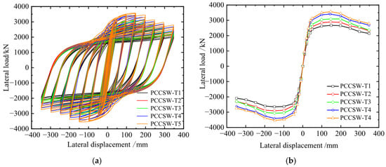
Figure 12.
Load–displacement curve of PCCSW-Ts: (a) hysteretic curves; (b) skeleton curves.
3.3.2. Analysis of Energy Dissipation
The correlations between comparable viscous damping coefficient he and PCCSW-Ts’ energy scattering are displayed in Figure 13. Compared with T1, the he of T2, T3, T4, and T5 increases by 2.07%, 3.25%, 0.30%, and 2.37%, respectively; the energy dissipation of T2, T3, T4, and T5 increases by 12.11%, 4.23%, 5.14%, and 4.23%, respectively. Therefore, the energy dissipation capacity of the structure can be accordingly enhanced by properly reducing the height-to-thickness ratio of corrugated steel plates. And below 510 for the steel plate’s height-to-thickness ratio, the specimen’s ductility, load-bearing capacity, and stiffness decrease rapidly. Therefore, it is recommended that the wave height is 4.5~6 mm, where the equivalent height-to-thickness ratio is 510~680.
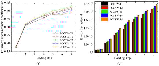
Figure 13.
Energy dissipation capacity of PCCSW-Ts: (a) he; (b) energy dissipation.
3.4. Effects of Wave Length of PCCSW
Several CSPWs with varying wave lengths (360, 400, 480, 520, and 560 mm) are planned in order to focus on how the wave length of the CSPW can affect hysteretic execution. The definite boundaries of PCCSW-Ls are displayed in Table 8.
Table 8.
The dimensions of specimen PCCSW-L.
3.4.1. Analysis of Load–Displacement Curves
The hysteresis loops of the PCCSW-L series are displayed in Figure 14. Compared with L1, the yield loads of L2, L3, L4, and L5 increase by 2.9%, 8.9%, 10%, and 11.3%, individually; the ductility decreases by 7%, 24.8%, 31.44%, and 33.24%, respectively. Increasing the wave length can somewhat increase the ability to support loads, but when the wave length is too long, the stiffener buckles more easily. Having analyzed the results, the ductility is better when the wave length of the specimen is 360~480 mm.
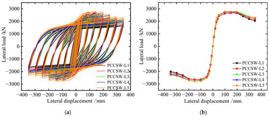
Figure 14.
Load–displacement curve of PCCSW-Ls: (a) hysteretic curves; (b) skeleton curves.
3.4.2. Analysis of Energy Dissipation
The comparisons between the energy dissipation capacity of the PCCSW-L series are displayed in Figure 15. Contrasted with L1, the he of L2, L3, L4, and L5 diminishes by 0.84%, 2.06%, 2.82%, and 3.91%, separately, and the energy dissipation diminishes by 0.52%, 8.01%, 8.36%, and 9.41%, individually. Hence, it is recognizable that raising the wave length of the creased steel plate will diminish the energy scattering limit of the example. At the point when the wave length is longer than 480 mm, the pliability diminishes maximally by 32% and the limit of stiffness misfortune is 92.9%. Subsequently, the suggested wave length in this paper is 360~480 mm.
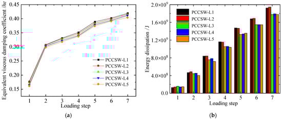
Figure 15.
Energy dissipation capacity of PCCSW-Ls: (a) he; (b) energy dissipation.
3.5. Effects of Width of Crossing Stiffeners on PCCSW
The most prominent factor affecting the out-of-plane stiffness of inclined stiffeners lies in the variations in their width. β represents the ratio of the flexural rigidity of the stiffener to that of the layered plate, and the computation process are as follows:
where the width of layered steel plates and the width of crossing stiffeners are denoted by h, B, and b, respectively; t1 and t are the thickness of crossing stiffeners and the thickness of corrugated steel plates, respectively; the angle between columns and crossing stiffeners is represented as α; d is the amplitude length of trapezoidal corrugated steel plates; η is the reduction factor of corrugated steel plates; and θ, a1, a2 are wave angle, length of horizontal section, and length of wave ridges of corrugated steel plates, as shown in Figure 16.
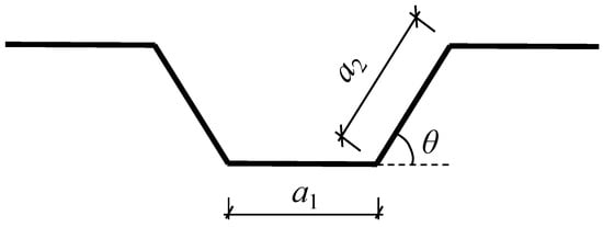
Figure 16.
Geometrical parameters.
For the purpose of concentrating on the influence of a range of widths of corner-to-corner stiffeners on the hysteretic performance of structure, five kinds of crossing stiffeners with distinct widths were devised. The specific parameters of specimen PCCSW-B are displayed in Table 9.
Table 9.
Parameters of specimens PCCSW-B.
3.5.1. Analysis of Load–Displacement Curves
The hysteresis loops of the PCCSW-B series are displayed in Figure 17. Because of the prohibitive impact of crossing stiffeners, expanding the width of stiffeners can further develop the bearing capacity. Compared with B1, the ultimate loads of specimens B2, B3, B4, and B5 increase by 1%, 4%, 5%, and 5%, respectively, and the ductility increases by 9.9%, 9.6%, 10.3%, and 5.6%, respectively. However, compared with B5, the width of stiffener of specimen B4 increases by 20 mm, but the maximum load-carrying capacity increases only by 3.13 kN; the ductility decreases. Properly increasing the width of stiffeners in this manner not only alleviates the out-of-plane buckling of steel plates but also further boosts the bearing capacity and malleability of the specimen.
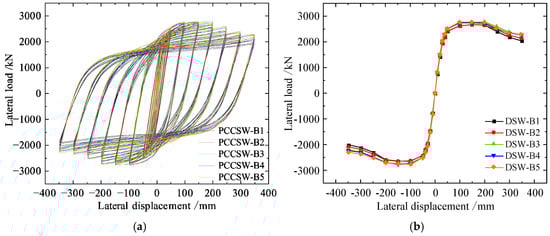
Figure 17.
Load–displacement curve of PCCSW-Bs: (a) hysteretic curves; (b) skeleton curves.
3.5.2. Analysis of Energy Dissipation
Figure 18 provides comparisons of energy dissipation for the PCCSW-M series with the same thickness. Compared with B1, the he of B2, B3, B4, and B5 increases by 0.59%, 0.93%, 0.97%, and 1.89%, respectively; the energy dissipation of B2, B3, B4, and B5 increases by 1.77%, 8.16%, 7.98%, and 8.51%, respectively. Consequently, the ability to consume energy can be marginally improved by increasing the width of crossing stiffeners. The ductility of the specimen will be reduced, as the width of the stiffener is greater than 90 mm or less than 50 mm. Therefore, it is suggested that the width of the stiffener is 50~90 mm and the stiffness ratio of the corresponding stiffener is 64.41~136.89.
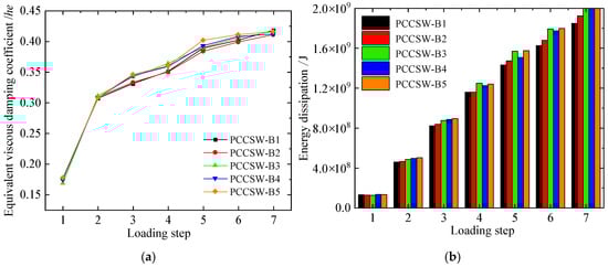
Figure 18.
Energy dissipation capacity of PCCSW-Bs: (a) he; (b) energy dissipation.
4. Calculation Method for Ultimate Shear Resistance
4.1. Theoretical Model of Specimen
When the boundary frame of the PCCSW reaches its maximum lateral resistance, plastic hinges form at the ends of the beams and columns [37,38]. It is estimated that a partial tension field is formed on the BCSPW when it reaches the maximum shear resistance. A mechanical diagram of the PCCSW model is proposed based on the suggestions by Berman and Bruneau [39], and it is presented in Figure 19. The shear resistance of each story of the PCCSW under the proposed mechanical model is calculated by the following [39]:
where is the shear load of the ith-story of the PCCSW, Hi is the height from the ith- story to the ground, and Fi is the shear load of the ith-story.
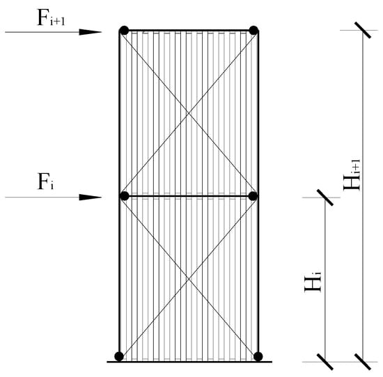
Figure 19.
Mechanical diagram of PCCSW.
is the plastic second limit of the limit outline. When the bearing capacity of the specimen attains its maximum value, the plastic hinges at the column tops and bottoms fail to form completely. This leads to a certain degree of reduction in the plastic moment capacity. When calculating the second plastic limit of the column, the attenuation coefficient is taken as 0.8 [32]; the calculation is shown in Equation (6).
where Wp and fy are plastic resistance moment and yield strength of columns, respectively.
The calculation method for the shear resistance of the PCCSW (Vw) is given by Equation (7):
where VC and vs. are shear resistance of CSPW and stiffeners, respectively.
Berman & Bruneau [39] and Clayton [40] established that the SPSWs can be considered as tension fields when determining the ultimate shear capacity; this has been followed by AISC [41]. However, for the beam-only-connected SPSWs, Guo et al. [42], Jiang et al. [33], and Hu et al. [29] laid out a partial tension field model. A mechanical model describing stress distribution was proposed for the PCCSW, with the establishment basis being the partial tension field model; it is shown in Figure 19. The shear-ruled zone and the shear-flexural zone are the two zones that are propounded by the mechanical outline.
The shear resistance VC is obtained by integrating τ(x), as shown in Equation (8):
where t is the width of the steel plate. In this formula, all parameters, except B1, are known.
In Figure 20, the normal stress on the shear-flexural zone edge of the corrugated steel plates is denoted by δy. The first one deals with normal stress while the second one accounts for shear stress, whereby stress combination in accordance with the von Mises yield equation is given in Equation (11). For stress state, in the shear-dominated zone, τ(x) = τy, so that by putting this into Equation (9), δy(x) = 0.
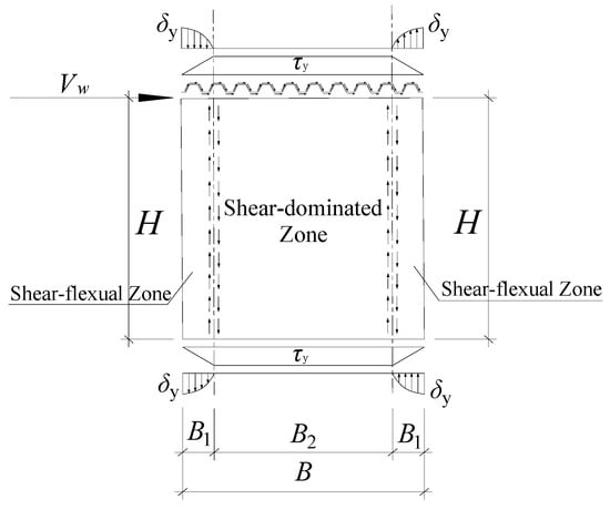
Figure 20.
Stress distribution of corrugated steel plates connected only by beam.
According to Tan et al. [43], the boundary stiffeners could change the area of the shear-dominated zone by changing the stiffness of them, and the length of B1 can be decreased accordingly. Once the stiffness of the boundary stiffeners reaches the threshold value in Equation (10) [31], all of the areas of the BCSPW can be estimated as shear-dominated zone, and B1 = 0 in this situation.
where H is the corrugated steel plate clear height; As is the section area of boundary stiffeners; As,min is the threshold section area; and fy,s is the material yield strength of the boundary stiffeners. The ratio of the section area of the boundary stiffeners to the threshold section area of the boundary stiffeners is defined as ζ, and it can be calculated by the following:
Based on Figure 20, the equilibrium equation for the edge of the shear-flexural zone can be expressed as Equation (12):
Shear stresses operating on the inclined plate of the corrugation plate can be canceled out in a direction perpendicular to the inclined plate since the inclined plate is symmetrical. Consequently, B1 and t continue to represent the shear stress pattern thickness and distribution length, respectively. The equivalent thickness te can be found using the following formula, which depends on the equivalent area:
where a1, a2, θ represent the straight plate length, inclined plate length, and wave angle of corrugated plate, respectively, and β1 represents the conversion coefficient of thickness.
By substituting Equation (9), Equation (11), and fy = τy into Equation (12), the expression of B1 can be obtained by the following:
VC can be obtained by the following:
Because the crossing stiffeners are relatively thin elements and can be buckled easily under compressive force, the results of them are not considered in the consequent vs. calculations. Similarly to the calculation of shear resistance of boundary frames, a coefficient of 0.8 is also considered to determine the tensile resistance of the crossing stiffeners, and it can be calculated by the following [44]:
where the angle between the horizontal direction and the diagonal stiffener is represented as θs. As is the cross-sectional area of the diagonal stiffener.
Finally, the ultimate shear resistance VW of the PCCSW can be obtained [44]:
4.2. Validation of the Theoretical Method
The first part of the validation is based on the FEM results. Due to the FEM models of this paper being double stories, the parameter n = 2 is thus in Equation (5). In addition, only the top of the second story is subjected to lateral load, where F1 = 0. Thus, the ultimate shear resistance of the PCCSW in the FE models can be calculated by the following [44]:
The other diameters as well as component performance in terms of material in the FEM models are considered in Equation (18) to obtain the theoretical ultimate shear resistance. Table 10 displays the contrast between the theoretical and FEM results for ultimate shear resistance.
Table 10.
Comparisons between ultimate shear resistance of theoretical and FEM results.
The second stage of validation is the test validation. In this paper, seven existing test specimens on the CSPW [43,44,45,46] are used to verify the theoretical model proposed in this paper. And the comparisons between the test results and theoretical results of ultimate shear resistance are summarized in Table 11.
Table 11.
Comparisons between ultimate shear resistance of theoretical and test results.
From the comparative results outlined in Table 10 and Table 11, we can conclude that the ultimate shear resistance forecasted by the theoretical model bears good agreement with both the FEM results and the experimental results. In most theoretical and FEM solutions, error is less than 10%, and the maximum error is 14.17%. The maximum error of data obtained in the experiment relative to the theoretical outcomes is 11.08%, and the majority of them are below 5%. The comparison shows that the proposed theoretical models have acceptable ability for the prediction of the ultimate shear strength of BCSPW and CSPW structures.
5. Conclusions
The partial-connected crossing-stiffened corrugated steel plate shear walls are proposed in this paper. The elastic buckling analysis and hysteretic analysis of the design are performed by using ABAQUS. The conclusion of the paper is as follows:
- (1)
- A FEM model of a single-span double-story PCCSW was established and was validated by comparing it to test results from a single-span double-story CSPW specimen. The findings demonstrate that the maximum error is less than 10% and that the initial stiffness and ultimate shear resistance as determined by FEM are essentially in agreement with the test results.
- (2)
- The results analyzed by FEM show that the shear resistance, lateral stiffness, energy dissipation capacity, and ductility of the PCCSW are better than those of the USW and BSW. Compared with the values of the USW and BSW, the maximum load of the PCCSW increases by 13% and 11%, respectively; the ductility factor increases by 21% and 24%, respectively; and the total energy dissipation increases by 23% and 20%, respectively.
- (3)
- The FEM models show that the material strength, the height-to-thickness ratio, the wave length, and the width of crossing stiffeners can impact the load-carrying capacity of the specimen. The analysis of wave height demonstrates that it ought to be 4.5~6 mm, and the height-to-thickness proportion ought to be 510~680 mm, wave length should be 360~480 mm, and width of crossing stiffeners should be 50~90 mm.
- (4)
- A theoretical model of the PCCSW is put forward; then, the shear-dominated zone and shear-flexural zone are determined to describe the real state of stress of the PCCSW and thus derive the shear resistance formula of the PCCSW. At the same time, the maximum deviation between theoretical outcomes and FEM outcomes is 14.17%, the maximum deviation between theoretical outcomes and experimental outcomes is 11.08%, and the greater part of them are under 10%. Given the current comparison results and considering the limitation that physical test data remains insufficient, these findings suggest that the proposed theoretical model has the potential to reasonably estimate the ultimate shear resistance of BCSPW and CSPW.
Author Contributions
Conceptualization, Y.S. (Yuntian Su), H.Z. and X.M.; methodology, Y.S. (Yuntian Su), X.M.; software, X.M.; validation, Y.S. (Yuntian Su) and X.M.; formal analysis, Y.W.; investigation, X.M., G.L., M.L. and L.W.; resources, H.Z.; data curation, Y.W. and Y.S. (Yanghang Shi); writing—original draft, X.M. and Y.S. (Yanghang Shi); writing—review and editing, Y.S. (Yuntian Su), X.M. and L.J.; visualization, X.M. and L.J.; supervision, H.Z.; project administration, H.Z., G.L. and L.W.; funding acquisition, Y.W. and M.L. All authors have read and agreed to the published version of the manuscript.
Funding
Thanks to the support from the Open Project of the Fujian Provincial Engineering Center for Application Technology of Green Buildings in 2022 (LSJZ22-02).
Data Availability Statement
The original contributions presented in this study are included in the article. Further inquiries can be directed to the corresponding authors.
Conflicts of Interest
Authors Yang Wu and Ming Liu were employed by the company 3rd Construction Co., Ltd. of China Construction 5th Engineering Bureau. Authors Guangping Li and Liyi Wang were employed by the company China Railway Urban Construction Group Co., Ltd. The remaining authors declare that the research was conducted in the absence of any commercial or financial relationships that could be construed as a potential conflict of interest.
References
- Tahaii, S.M.; Hamidi, H.; Amiri, J.V. Inelastic Seismic Demand of Steel-Plate Shear Wall Structures: Emphasis on the PTD Effect. Int. J. Civ. Eng. 2022, 20, 1145–1163. [Google Scholar] [CrossRef]
- Milad, B.; Tadeh, Z.; Mojtaba, G.; James, B.; George, C.; Mohammad, H. Study of influences of partial plate–frame connection on the cyclic behavior and performance of LYP corrugated SPSW system. Arch. Civ. Mech. Eng. 2024, 24, 105. [Google Scholar] [CrossRef]
- Jiang, L.; Zheng, H.; Hu, Y. Experimental seismic performance of steel-and composite steel-panel wall strengthened steel boundary frames. Arch. Civ. Mech. Eng. 2017, 17, 520–534. [Google Scholar] [CrossRef]
- Zhao, X.; Zhou, F.; Li, Y.T. Theoretical and experimental investigations of steel plate shear walls with diamond openings. Thin-Walled Struct. 2023, 189, 110838. [Google Scholar] [CrossRef]
- Zhang, X.; Chen, Y.; Qiao, H. Investigation on hysteretic performance of assembled H-shaped steel frame-corrugated steel plate shear wall with different corrugated orientation and wavelength. J. Build. Eng. 2023, 77, 107473. [Google Scholar] [CrossRef]
- Zhang, X.; Guo, Y. Behavior of steel plate shear walls with pre-compression from adjacent frame columns. Thin-Walled Struct. 2014, 77, 17–25. [Google Scholar] [CrossRef]
- Ye, J.; Jiang, L. Collapse mechanism analysis of a steel moment frame based on structural vulnerability theory. Arch. Civ. Mech. Eng. 2018, 18, 833–843. [Google Scholar] [CrossRef]
- Lv, Y.; Li, L.; Wu, D.; Chen, Y.; Li, Z.; Chouw, N. Shear-displacement diagram of steel plate shear walls with precompression from adjacent frame columns. Struct. Des. Tall Spec. Build. 2019, 28, e1585. [Google Scholar] [CrossRef]
- Zhang, W.; Lin, J.; Huang, Y.; Lin, B.; Liu, X. Experimental and numerical studies on flexural performance of composite beams under cyclic loading. Structures 2024, 70, 107728. [Google Scholar] [CrossRef]
- Suo, Y.; Fan, S.; Li, C.; Zeng, S.; Liu, C. Parametric analysis on hysteresis performance and restoring force model of LYP steel plate shear wall with two-side connections. Int. J. Steel Struct. 2020, 20, 1960–1978. [Google Scholar] [CrossRef]
- Cheng, X.; Jiang, L.; Hu, Y.; Zhang, X. Cyclic Tests and Modeling of CFS Structures with CFRP-Toughened Screws and Special Shape Built-Up End Studs. J. Struct. Eng. 2025, 151, 7. [Google Scholar] [CrossRef]
- Haddad, O.; Sulong, N.H.R.; Ibrahim, Z. Cyclic performance of stiffened steel plate shear walls with various configurations of stiffeners. J. Vibroengineering 2018, 20, 459–476. [Google Scholar] [CrossRef]
- Mu, Z.; Yang, Y. Experimental and numerical study on seismic behavior of obliquely stiffened steel plate shear walls with openings. Thin-Walled Struct. 2020, 146, 106457. [Google Scholar] [CrossRef]
- Labibzadeh, M.; Salehnia, A.; Hossain, K.; Jing, D. Comparison of Performance of the Flat, Trapezoidal and Sinusoidal Steel Plate Shear Walls Under Cyclic Loads. Iran. J. Sci. Technol. Trans. Civ. Eng. 2022, 46, 3571–3589. [Google Scholar] [CrossRef]
- Zhu, B.; Tong, J.; Zhang, J.; Guo, Y. Shear-resistant capacity and design of orthogonal double-corrugated-plate shear walls. Thin-Walled Struct. 2023, 187, 110759. [Google Scholar] [CrossRef]
- Vaziri, E.; Gholami, M.; Azandariani, M.G. The Wall–Frame Interaction Effect in Corrugated Steel Plate Shear Walls Systems. Int. J. Steel Struct. 2021, 21, 1680–1697. [Google Scholar] [CrossRef]
- Ghodratian-Kashan, S.M.; Maleki, S. Experimental investigation of double corrugated steel plate shear walls. J. Constr. Steel Res. 2022, 190, 107138. [Google Scholar] [CrossRef]
- Wen, C.; Zhu, B.; Sun, H.; Guo, Y.; Zheng, W.; Deng, L. Global stability design of double corrugated steel plate shear walls under combined shear and compression loads. Thin-Walled Struct. 2024, 199, 111789. [Google Scholar] [CrossRef]
- Hosseinzadeh, L.; Mofid, M.; Aziminejad, A.; Emami, F. Elastic interactive buckling strength of corrugated steel shear wall under pure shear force. Struct. Des. Tall Spec. Build. 2017, 26, e1357. [Google Scholar] [CrossRef]
- Hosseinzadeh, L.; Emami, F.; Mofid, M. Experimental investigation on the behavior of corrugated steel shear wall subjected to the different angle of trapezoidal plate. Struct. Des. Tall Spec. Build. 2017, 26, e1390. [Google Scholar] [CrossRef]
- Cao, Q.; Huang, J.; Zhao, L.; Fang, Z.; Zhang, Z. Research on shear performance of corrugated steel plate shear walls with inelastic buckling of infilled plates under lateral loads. J. Build. Eng. 2022, 52, 104406. [Google Scholar] [CrossRef]
- Tong, J.; Guo, Y.; Zuo, J.; Gao, J. Experimental and numerical study on shear resistant behavior of double-corrugated-plate shear walls. Thin-Walled Struct. 2020, 147, 106485. [Google Scholar] [CrossRef]
- Tong, J.; Guo, Y.; Pan, W. Ultimate shear resistance and post-ultimate behavior of double-corrugated-plate shear walls. J. Constr. Steel Res. 2020, 165, 105895. [Google Scholar] [CrossRef]
- Dou, C.; Zhang, J.; Lan, T.; Wang, D.; Zhang, G. Elastic shear buckling analysis of infill panels in trapezoidal corrugated plate shear walls. Thin-Walled Struct. 2025, 215, 13452. [Google Scholar] [CrossRef]
- Ghodratian-Kashan, S.M.; Maleki, S. Experimental and numerical study of beam-only-connected corrugated steel plate shear walls. J. Earthq. Eng. 2024, 28, 1769–1791. [Google Scholar] [CrossRef]
- Dou, C.; Pi, Y.; Gao, W. Shear resistance and post-buckling behavior of corrugated panels in steel plate shear walls. Thin-Walled Struct. 2018, 131, 816–826. [Google Scholar] [CrossRef]
- Jiang, L.; Zhang, X.; Jiang, L.; He, C.; Ye, J.; Ran, Y. Fundamental period estimation of steel boundary frames equipped with steel panel walls. Struct. Eng. Mech. 2021, 78, 715–729. [Google Scholar]
- Jiang, L.; Jiang, L.; Hu, Y.; Ye, J.; Zheng, H. Seismic life-cycle cost assessment of steel boundary frames equipped with steel panel walls. Eng. Struct. 2020, 211, 110399. [Google Scholar] [CrossRef]
- Hu, Y.; Zhao, J.; Zhang, D.; Zhang, H. Cyclic tests of fully prefabricated concrete-filled double-skin steel tube/moment-resisting boundary frames with beam-only-connected steel plate shear walls. Thin-Walled Struct. 2020, 146, 106272. [Google Scholar] [CrossRef]
- Paslar, N.; Farzampour, A.; Hatami, F. Infill plate interconnection effects on the structural behavior of steel plate shear walls. Thin-Walled Struct. 2020, 149, 106621. [Google Scholar] [CrossRef]
- Guo, L.; Rong, Q.; Qu, B.; Liu, J. Testing of steel plate shear walls with composite columns and infill plates connected to beams only. Eng. Struct. 2017, 136, 165–179. [Google Scholar] [CrossRef]
- Zheng, H.; Zhang, Z.; Jiang, L.; Hu, Y.; Wang, W. Cyclic performance and shear resistance design of asymmetric diagonal stiffened beam-only-connected corrugated steel plate shear walls. Archiv. Civ. Mech. Eng. 2022, 22, 183. [Google Scholar] [CrossRef]
- Jiang, L.; Ye, J.; Zheng, H. Macroscopic modelling of steel boundary frames equipped with bolt-connected reinforced concrete panel wall. Eng. Struct. 2020, 213, 110549. [Google Scholar] [CrossRef]
- Chu, Z.; Jin, Y.; Wei, Z. Hysteretic performance of steel plate shear wall reinforced with PET-infilled diagonal CFRP multi-layer corrugated plate. Thin-Walled Struct. 2025, 218, 113968. [Google Scholar]
- Yang, S.; Jin, S.; Wang, Q. Modular corrugated steel plate shear wall: The relationship of matching with boundary column in terms of stiffness and strength. J. Constr. Steel Res. 2025, 227, 109341. [Google Scholar] [CrossRef]
- JGJ/99-2015; Technical Specification for Steel Structure of Tall Building. Chinese Architecture & Building Press: Beijing, China, 2015.
- Shi, G.; Gao, Y.; Wang, X.; Zhang, Y. Low Cycle Fatigue Properties of Low Yield Point Steels. China Civ. Eng. J. 2019, 52, 20–26+52. [Google Scholar]
- Jiang, L.; Zheng, H.; Hu, Y. Effects of various uncertainties on seismic risk of steel boundary frame equipped with steel panel wall. Bull. Earthq. Eng. 2018, 16, 5995–6012. [Google Scholar] [CrossRef]
- Berman, J.; Bruneau, M. Plastic analysis and design of steel plate shear walls. J. Struct. Eng. 2003, 129, 1448–1456. [Google Scholar] [CrossRef]
- Ozcelik, Y.; Clayton, P.M. Seismic design and performance of SPSWs with beam-connected web plates. J. Constr. Steel Res. 2018, 142, 55–67. [Google Scholar] [CrossRef]
- ANSI/AISC 341-05; AISC Seismic Provisions for Structural Steel Buildings. American Institute of Steel Construction: Chicago, IL, USA, 2005.
- Hou, J.; Guo, L.; Yan, J. Steel plate–restraining panel interaction behavior in buckling-restrained steel plate shear walls. Thin-Walled Struct. 2021, 169, 108348. [Google Scholar] [CrossRef]
- Tan, P.; Wei, Y.; Li, Y.; Zhou, F. Experimental Research on Seismic Behavior of Corrugated Steel Plate Shear Wall. China Civ. Eng. J. 2018, 51, 8–15. [Google Scholar]
- Hao, B. Cyclic Test Vertically Corrugated Steel Plate Shear Walls with Various Openings. Ph.D. Thesis, Tianjin University, Tianjin, China, 2018. [Google Scholar]
- Li, N. Experimental Research on Seismic Behavior of Corrugated Steel Plate Shear Wall System. Ph.D. Thesis, Tianjin University, Tianjin, China, 2017. [Google Scholar]
- Zhao, Q.; Qiu, J.; Hao, B.; Wang, Q. Lateral Behavior of Vertically-corrugated Steel Plate Shear Walls Connected with Beams Only. J. Tianjin Univ. (Sci. Technol.) 2019, 52, 46–53. [Google Scholar]


Disclaimer/Publisher’s Note: The statements, opinions and data contained in all publications are solely those of the individual author(s) and contributor(s) and not of MDPI and/or the editor(s). MDPI and/or the editor(s) disclaim responsibility for any injury to people or property resulting from any ideas, methods, instructions or products referred to in the content. |
© 2025 by the authors. Licensee MDPI, Basel, Switzerland. This article is an open access article distributed under the terms and conditions of the Creative Commons Attribution (CC BY) license (https://creativecommons.org/licenses/by/4.0/).