1. Introduction
Recent engineering practices have shown that composite material structures, owing to their excellent mechanical properties, ease of construction, and significant economic advantages, are widely applied in the fields of large-scale building structures and bridge engineering [
1,
2,
3]. As a critical load-bearing component in composite material structural systems, the performance of shear connectors directly affects the overall load-bearing capacity of the structure. PBL shear connectors, derived from perfobond steel plates, have increasingly become vital load-transmitting elements in steel–concrete composite structures due to their outstanding shear capacity, reliable fatigue performance, and superior ductility characteristics. Especially in the domain of large-span bridge engineering, with the growing adoption of new structural types such as steel–concrete composite beams and hybrid cable-stayed bridges, the optimization of the mechanical performance and durability design of shear connectors has become a key technological challenge that affects both the safety and economic efficiency of the structure [
4,
5].
Convenience during construction, great fatigue resistance, and enhanced structural rigidity are three major advantages of traditional PBL shear connectors, which utilize a perfobond steel plate configuration to provide the shear resistance mechanism of concrete shear dowel [
6,
7]. With the progressive development of modern bridge engineering technologies, the application scope of this connector system in composite bridges has expanded from conventional beam connectors to more complex load-bearing scenarios, such as hybrid structural joints and temporary anchoring systems in cantilever construction. However, engineering practices indicate that multi-row and multi-column arrangements of shear connectors can lead to significant shear stress concentration at the steel–concrete interface, resulting in interface damage accumulation that may compromise the structural durability and fatigue life [
8,
9,
10,
11]. To address this critical issue, recent research has focused on optimizing and innovating the load transfer mechanism of connectors. The latest experimental studies indicate that the incorporation of new structural solutions, such as foam-filled T-section structures and rubber vibration-damping sleeve composite studs, can significantly improve the uniformity of shear transfer in composite sections. Among these innovations, the rubber sleeve and PBL composite connector, through the stress buffering effect of elastic materials, has been proven to exhibit superior stress redistribution capabilities under cyclic loading [
12,
13,
14,
15]. The application of AI predictive technologies in the advanced modeling of structural connectors can provide novel insights for enhancing structural safety and predictive accuracy [
16]. These technological advancements provide new solutions for enhancing the overall performance and service life of composite structures.
Research on PBL shear connectors has primarily focused on experimental investigations and finite element analysis (FEA) techniques [
17,
18,
19,
20]. Liu et al. [
14,
21] proposed the incorporation of rubber rings to alleviate the stress concentration issues in PBL shear connectors and validated their effectiveness in improving the initial stiffness and ductility of the connectors through push-out tests and finite element simulations. The finite element method has been demonstrated as an effective tool for simulating the entire testing process, significantly reducing the associated testing costs [
14,
16,
17,
18].
Although finite element analysis of single PBL rubber-ring shear connectors has been conducted in existing studies (such as Liu et al. [
14,
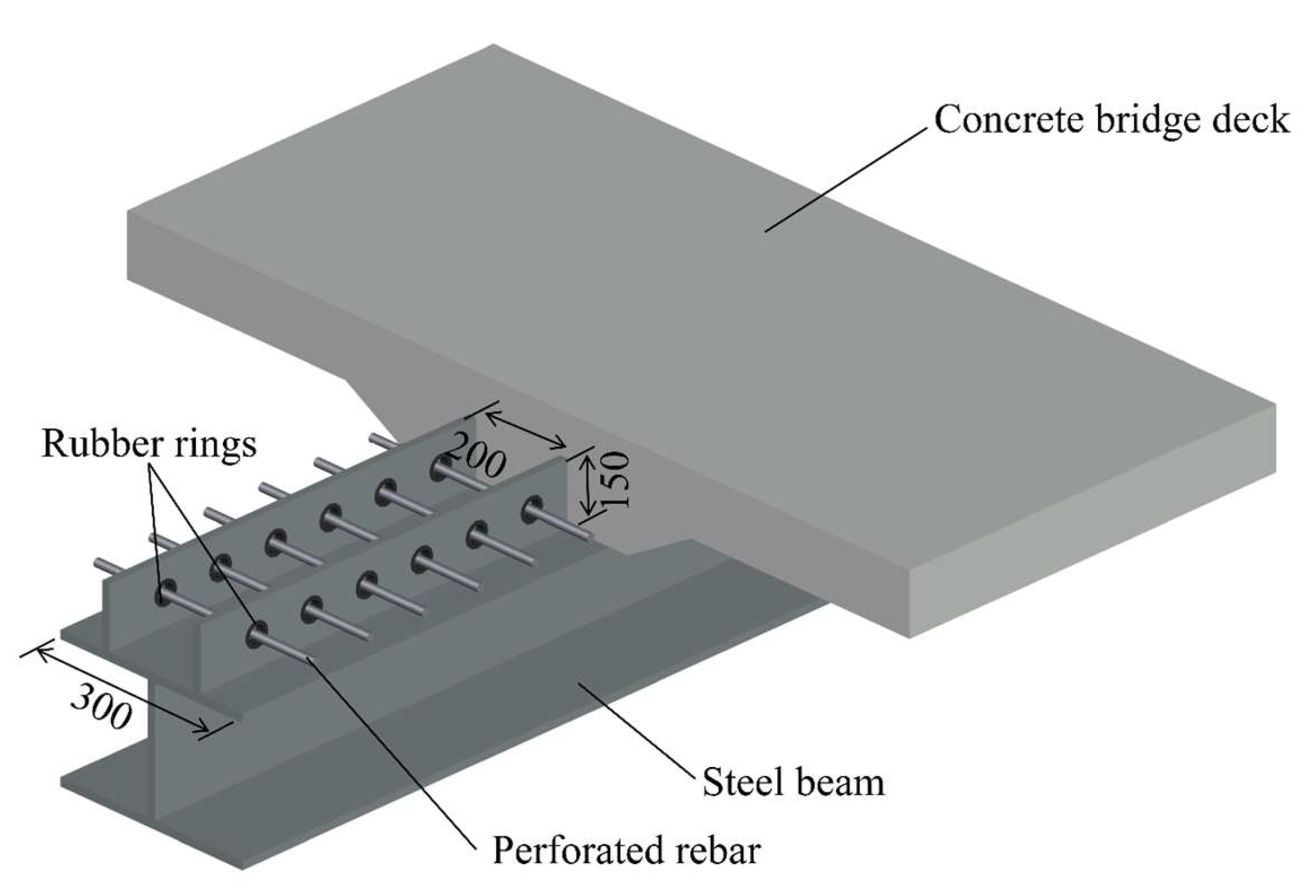
21]), the research on the refined finite element model of Twin-PBL rubber-ring shear connectors is still blank. This study established for the first time a three-dimensional finite element model of Twin-PBL rubber-ring connectors considering the superelasticity of rubber, the damage plasticity of concrete, and the complex interaction between reinforcing bars and concrete, systematically revealing its shear force transfer mechanism and failure mode under this more complex configuration (as shown in
Figure 1).
This study established a total of 23 finite element models using solid finite element analysis to systematically investigate the mechanical behavior of Twin-PBL rubber-ring shear connectors. These models encompass a range of geometric dimensions and material strengths to comprehensively evaluate the connector’s performance under various operating conditions. Through comparative analysis, the significant influences of parameters such as rubber ring thickness, perforated rebar diameter, and material strength on the shear performance of the connector are revealed, providing essential theoretical foundations for optimized design. The objective is to deepen the understanding of their shear performance and to evaluate the effects of the rubber ring and other design parameters on the overall shear resistance of the connector.
By comparing with the most representative previous works, the innovations and contributions of this study are mainly reflected in the following three aspects. Firstly, this study systematically investigates the role of rubber rings under the double PBL configuration for the first time, which better aligns with the actual stress conditions of multi-row connectors in engineering. Secondly, the model can more accurately reflect the real mechanical behavior of multi-component collaborative work, especially the interaction between double concrete dowels and rubber rings. Thirdly, a more comprehensive understanding of the influence laws of design parameters has been obtained, and on this basis, the first shear capacity calculation formula specifically for Twin-PBL rubber ring connectors is proposed.
2. Design of Twin-PBL Rubber-Ring Shear Connector
Natural rubber was employed for the rubber rings, C60 concrete was applied for the concrete slabs, Q345 steel was used for the H-beam and perfobond plates, and HRB400-grade hot-rolled steel bars were selected for the rebars in the connectors. In particular, the structural rebar was 16 mm in diameter, the rubber ring was 4 mm thick, and the perforated rebar was 20 mm in diameter. To decrease the effect of end-bearing pressure from the concrete, foam blocks were positioned at the leading edge of the perfobond plate in the direction of its sliding. All dimensional parameters are illustrated in
Figure 2.
3. Finite Element Analysis
3.1. Modeling Details and Element Selection
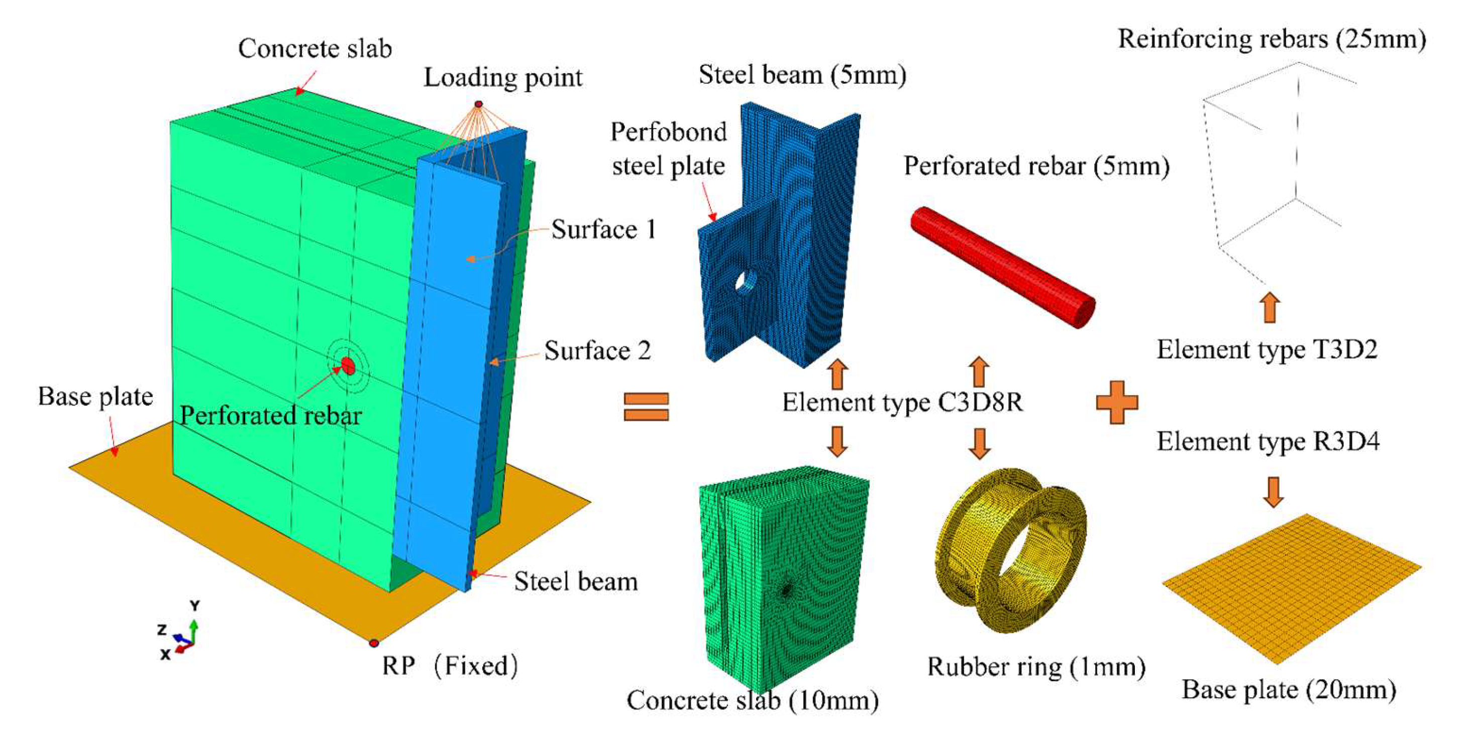
To thoroughly investigate the internal failure mechanism of Twin-PBL rubber-ring shear connectors, ABAQUS/Explicit was employed for comprehensive modeling and simulation analyses. Considering the biaxial symmetry of the model, a quarter model of the push-out test was developed, including a single perfobond plate connector. The detailed configuration of this model is illustrated in
Figure 3. In the model, the total time for the analysis step is set to 0.1 s, with no mass scaling applied, ensuring that the ratio of kinetic energy to internal energy is less than 1%. Through this modeling and simulation methodology, the understanding of the mechanical behavior and failure mechanisms of the connector under loading conditions was significantly improved.
In the finite element simulation of Twin-PBL rubber-ring shear connectors under pull-out loading, a combination of solid, truss, and rigid element types was utilized for meshing. Specifically, the concrete slab, perforated rebar, rubber ring, perfobond steel plate, and steel beam were discretized using C3D8R solid elements, while the other reinforcements were modeled using T3D2 truss elements. The base plate was defined as an R3D4 rigid element. In order to optimize the use of computational resources, the global mesh was set to a relatively coarse 10 mm, except for the concrete dowel, perforated rebar, perfobond steel plate and rubber ring, which require finer meshing. However, for more complex stress distribution regions, such as the concrete dowel, rubber ring, perfobond steel plate and perforated rebar, a refined mesh was applied to ensure the accuracy of the simulation results. This meshing strategy effectively balances computational efficiency with result precision, providing a reliable foundation for subsequent analysis.
3.2. Boundary Conditions and Constraints
Symmetric constraints are applied in the x-direction on Surface 1 and in the z-direction on Surface 2, as shown in
Figure 3. Coupling constraints are implemented to link the loading surface of the steel beam with the loading point. The perforated rebar is connected to the concrete dowel using tie constraints, while surface-to-surface contact is defined between the remaining components. The coefficient of friction between the concrete slab and the base plate is assigned a value of 0.5 [
6], while the friction coefficients for other contact pairs are set to zero. The normal behavior of the contact surfaces is defined as “hard” pressure-overclosure, indicating that the interface cannot be penetrated but may separate. Displacement-controlled loading is applied in the simulation to improve convergence, enable precise control over the deformation process, simplify the application of complex loading conditions, and facilitate the extraction of simulation results.
3.3. Material Modeling
3.3.1. Material Constitution of Concrete
Given that the primary failure modes of concrete observed in the experiments are tensile cracking and crushing, and referring to relevant literature [
19,
22,
23], the Concrete Damaged Plasticity (CDP) model with the following calibrated parameters are adopted: Dilation angle:
ψ = 30°; Eccentricity:
ε = 0.1; Biaxial strength ratio:
fb0/fc0 = 1.16; Stress ratio:
K = 0.6667; Viscosity parameter:
μ = 0.0005. Where
fb0/
fc0 denotes the ratio of the initial equibiaxial compressive yield stress to the initial uniaxial compressive yield stress. The parameter
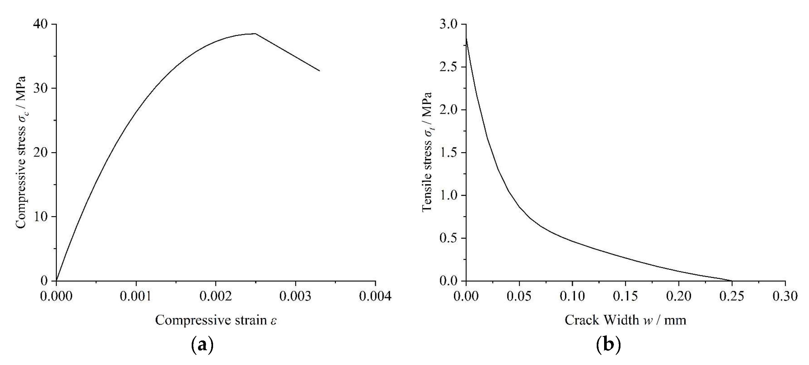
K represents the ratio of the second stress invariant on the tensile meridian to that on the compressive meridian. The dilation angle defines the volumetric expansion characteristics of concrete during plastic deformation, namely the extent of volume change in the material under shear loading. The eccentricity governs the hyperbolic shape of the flow potential function, specifically delineating the deviation of the flow potential asymptote relative to the hydrostatic pressure axis. The stress–strain relationship under compressive loading and the stress-crack width relationship under tensile loading are presented in
Figure 4.
This study adopts the stress–strain relationship for uniaxial concrete compression based on the nonlinear constitutive model proposed in CEB-FIP MC 2010 [
24], due to the complexity of the concrete constitutive behavior. As shown in
Figure 4, the stress–strain curve is divided into an ascending branch and a descending branch. The ascending branch is defined using Equations (1)–(3), while the descending branch is assumed to be linear and terminates when the stress reaches 0.85
ƒck. The ultimate strain
εcu corresponding to 0.85
ƒck is designated as 0.0033 [
25], facilitating the calculation of the descending branch by Equation (4).
The tensile strength of concrete is determined based on its splitting tensile strength obtained from material testing and Equation (5). Furthermore, considering the nonlinear constitutive relationship delineated by CEB-FIP MC 1990 [
26], the stress-crack width relationship proposed by Hordijk et al. [
27] is employed to characterize the post-cracking tensile behavior of concrete. The tensile softening curve is computed utilizing Equation (6).
where
w denotes the crack width;
wc represents the crack width at zero tensile stress, expressed as
wc = 5.14G
F/
ft (mm);
GF signifies the fracture energy necessary to generate a unit area of stress-free crack surface, defined by
GF = 0.073
fc0.18 (N/mm); the constants
c1 and
c2 are assigned values of 3 and 6.93, respectively.
3.3.2. Steel Material Constitutive Properties
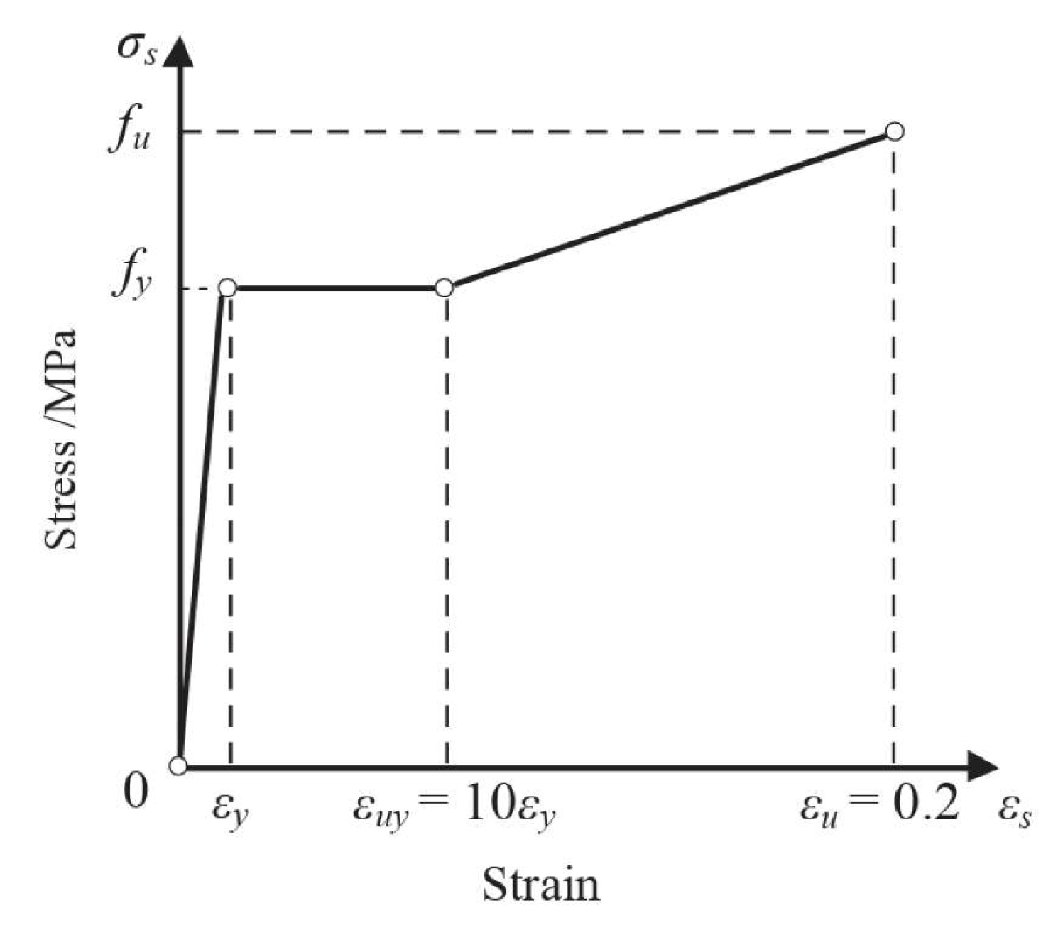
The steel plates and reinforcement bars are represented using a three-segment idealized elastoplastic hardening model with strain hardening behavior [
14], as shown in
Figure 5. This model consists of three distinct stages that describe the mechanical behavior of the steel components. Once the ultimate stress
fu and corresponding ultimate strain
εu, are reached, ABAQUS automatically transitions to a horizontal branch in the stress–strain curve. The ultimate strain
εu is defined as 0.2.
3.3.3. Rubber Material Constitutive Properties
To accurately characterize the rubber ring as an isotropic hyperelastic material, the strain energy potential model from ABAQUS is employed. Given that the rubber ring is mechanically constrained by the concrete slab and the perfobond steel plate, a simplified polynomial form is selected for its constitutive description. The corresponding material parameters are obtained from the literature [
14], including the coefficients
C10 = 0.587 MPa,
C20 = 0.0143 MPa,
D1 = 0.0866 MPa
−1, and
D2 = 0.
4. Shear Mechanism Analysis
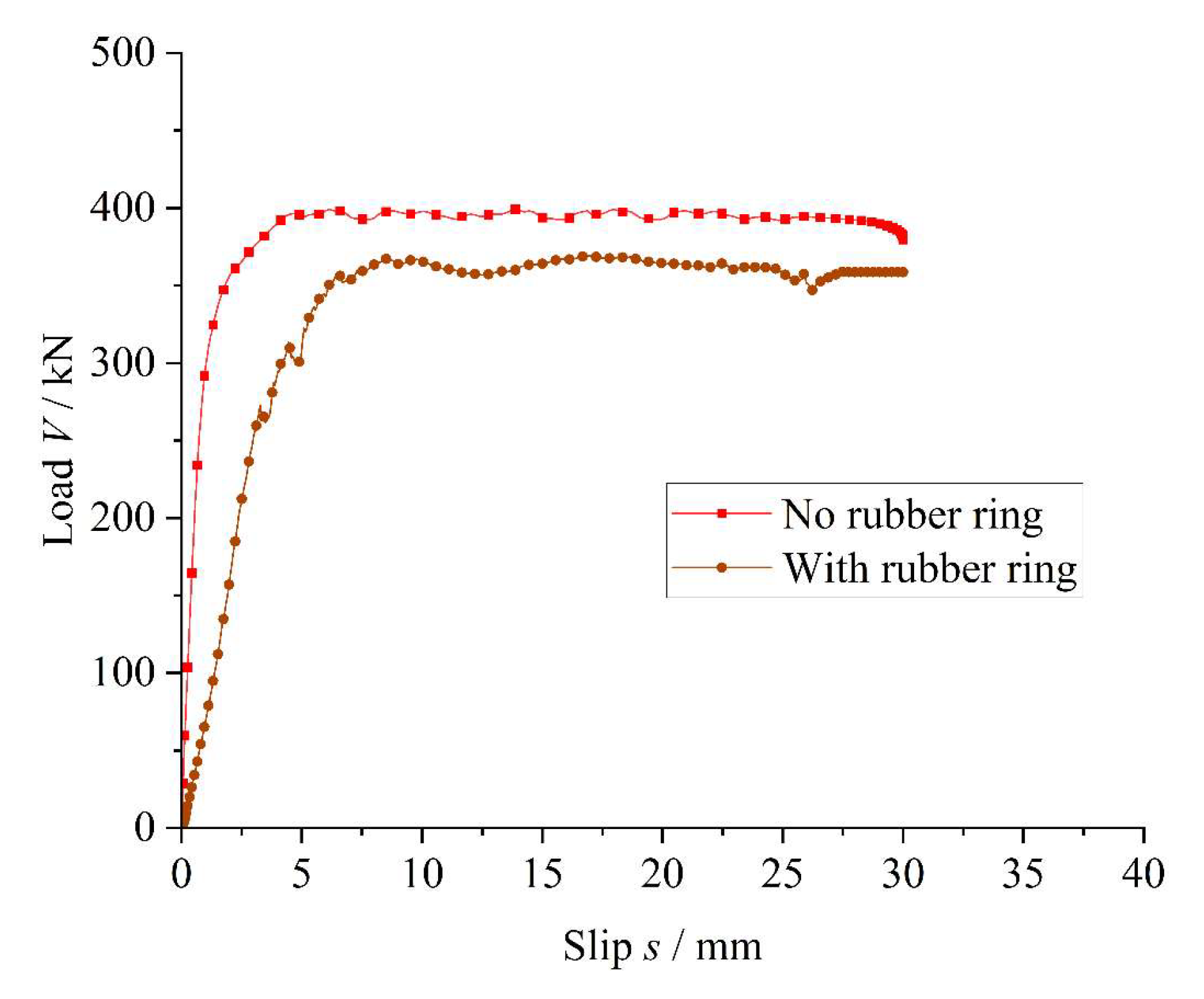
This study employed solid finite element modeling and analytical methods to establish models of both the conventional Twin-PBL shear connector and the Twin-PBL rubber-ring shear connector. When the rubber ring thickness in the Twin-PBL rubber-ring shear connector is set to 4 mm, the load–slip curve shown in
Figure 6 exhibits three distinct stages. The first stage is characterized by a steep elastic response, followed by a nonlinear plastic phase, and finally a quasi-linear phase, during which the slip increases significantly while the load remains almost constant. Throughout the loading process, the shear stress is gradually transferred from the perfobond steel plate to the rubber ring, concrete dowel, and perforated rebar. As long as the concrete dowel remains intact, the curve remains in the elastic phase. Once the concrete dowel begins to degrade and the primary load is transferred to the perforated rebar, the curve transitions into the plastic phase. Finally, when the concrete dowel is completely crushed and the majority of the load is carried by the perforated rebar, the curve approaches a nearly linear trajectory.
The yield slip (
Sy) is defined as the relative slip corresponding to the yield load (
Vy), while the shear stiffness (
Ks) is calculated as
Vy/
Sy. As shown in
Figure 6, the conventional Twin-PBL shear connector exhibited a yield load (
Vy) of 304.7 kN, an ultimate shear capacity (
Vu) of 399.1 kN, and a shear stiffness (
Ks) of 287.5 kN/mm. In contrast, the Twin-PBL rubber-ring shear connector exhibited corresponding values of 266.9 kN, 369.1 kN, and 84.4 kN/mm. In comparison to the conventional Twin-PBL shear connector, the yield load (
Vy), ultimate shear capacity (
Vu), and shear stiffness (
Ks) of the Twin-PBL rubber-ring shear connector decreased by 16.9%, 7.5%, and 70.6%, respectively. These results indicate that the incorporation of the rubber ring significantly reduces the shear stiffness (
Ks), while the reduction in ultimate shear capacity (
Vu) is relatively minor. The primary reason for this situation is that the rubber ring possesses relatively low stiffness and contributes little to shear resistance, thereby reducing the overall stiffness of the connector. Additionally, with the diameter of the steel plate openings held constant, the presence of the rubber ring decreases the effective diameter of the concrete dowel, which in turn reduces its shear capacity. Furthermore, as rubber is an isotropic hyperelastic material with high deformability, the addition of the rubber ring significantly increases the yield displacement of the connector, thus improving its ductility.
5. Parametric Study
To thoroughly investigate the factors influencing the shear performance of Twin-PBL rubber-ring shear connectors, a total of 23 finite element models were developed in this study for systematic simulation and analysis. This study focused on five key parameters which are considered to significantly affect the shear performance of the connectors. These parameters include rubber ring thickness (tr), perforated rebar diameter (dr), concrete strength (fcu), perforated rebar strength (fry), perfobond steel plate strength (fsy). Through the analysis of these parameter variations, a more comprehensive understanding of their specific effects on the shear performance of the connectors can be obtained.
The specific results of the parametric analysis are summarized in
Table 1, which provides detailed information on the shear performance of the connectors under different parameter combinations, including yield load, shear stiffness and other relevant indexes.
5.1. Impact of Rubber Ring Thickness
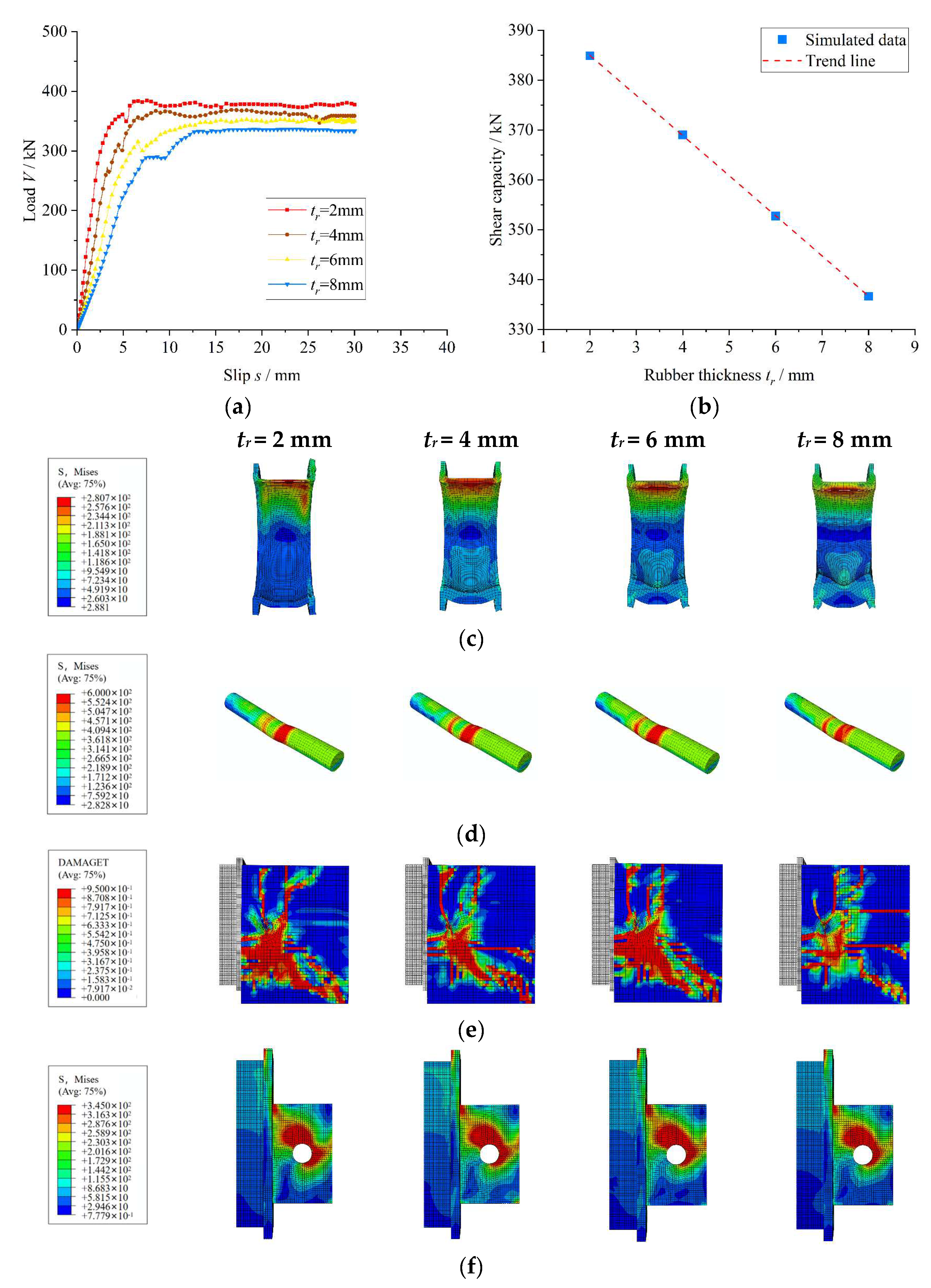
The load–slip response and stress distribution characteristics of the Twin-PBL rubber-ring shear connector with varying rubber ring thicknesses are shown in
Figure 7. With a fixed perfobond steel plate diameter, as the rubber ring thickness increases from 2 mm to 4 mm, 6 mm, and 8 mm—corresponding to a reduction in concrete dowel thickness from 26 mm to 22 mm, 18 mm, and 14 mm, respectively—the yield load (
Vy) decreases by 7.6%, 18.8%, and 20.8%, while the shear stiffness (
Ks) decreases by 32.6%, 52%, and 63.9%. These results demonstrate a consistent decline in both
Vy and
Ks with increasing rubber ring thickness. The reduction in ultimate shear capacity (
Vu) by 4.1%, 8.4%, and 12.5% further confirms that the thickening of the rubber ring diminishes shear capacity by reducing the effective cross-sectional area of the concrete dowel.
Notably, the stress distribution characteristics (
Figure 7c–f) reveal that the stress concentration in the rubber ring is alleviated as its thickness increases. Meanwhile, the stress levels in the perforated rebar and perfobond steel plate do not change significantly, and the tensile damage of the concrete slab is reduced. This phenomenon arises from the fact that, with a constant perfobond steel plate diameter, the increase in rubber ring thickness reduces the concrete dowel thickness and weakens the shear capacity. However, through material stiffness reconstruction, the stress concentration at the interface between the rubber ring and the perfobond steel plate is effectively dispersed, and the load transfer path is optimized, thereby improving the stress state of the concrete slab.
5.2. Impact of Perforated Rebar Diameter
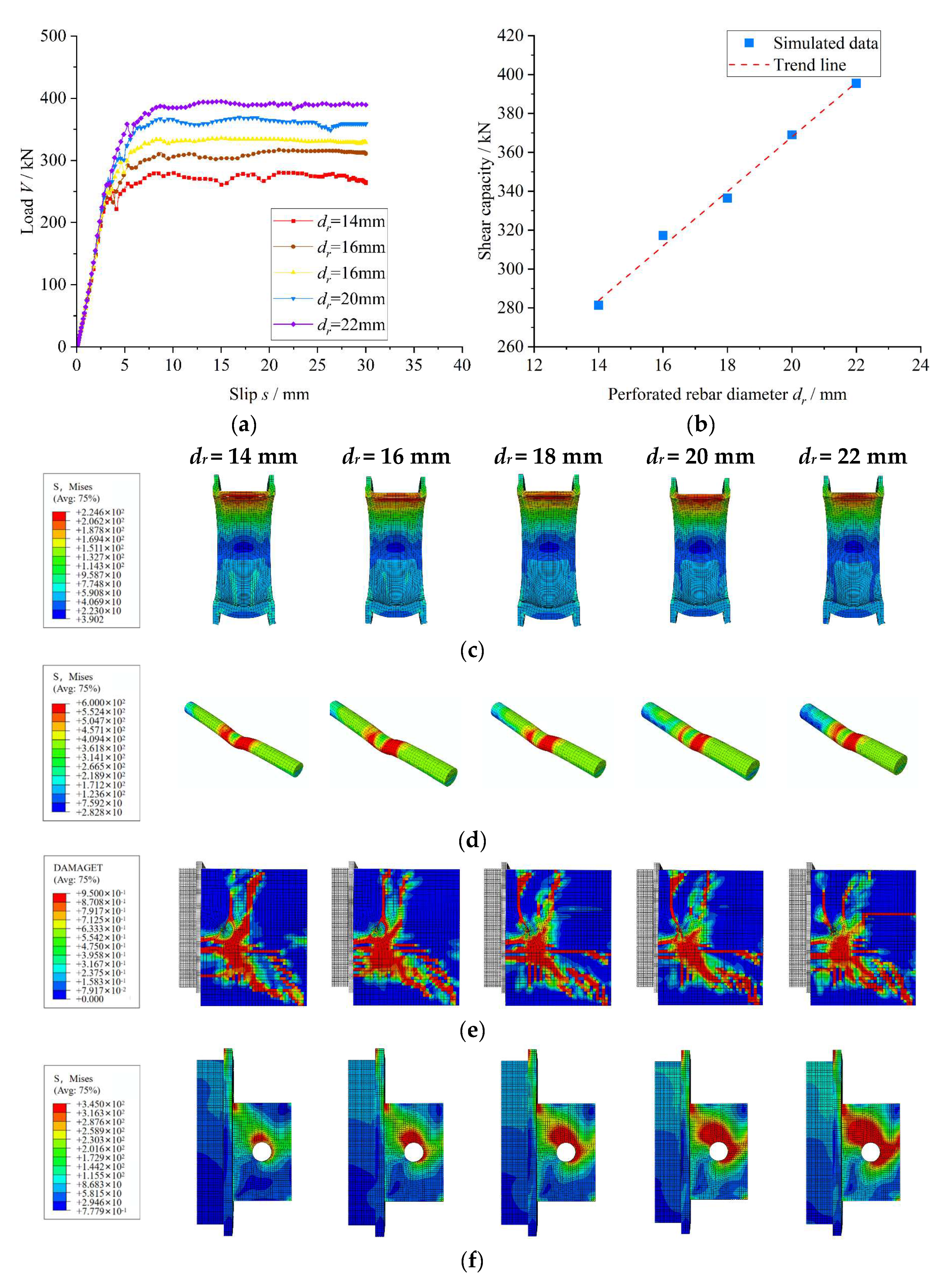
Figure 8 presents the load–slip response and stress distribution characteristics of the Twin-PBL rubber-ring shear connector with identical rubber ring thicknesses. Under a fixed perfobond steel plate diameter, when the perforated rebar diameter increases from 14 mm to 16 mm, 18 mm, 20 mm, and 22 mm, the shear capacity (
Vu) increases by 12.8%, 19.6%, 31.2%, and 40.6%, respectively. The yield load (
Vy) increases by 0.8%, 1.3%, 13.0%, and 17.9%, while the shear stiffness (
Ks) increases by 2.6%, 4.9%, 9.2%, and 12.0%, correspondingly. These results indicate that an increase in the perforated rebar diameter leads to a consistent upward trend in all three performance parameters, highlighting that the rebar diameter is a key factor influencing the shear performance of the connector.
The stress distribution features (
Figure 8c–f) indicate that the stress concentration in the rubber ring intensifies as its diameter increases. Meanwhile, the stress levels in the perforated rebar and perfobond steel plate remain relatively stable, while tensile damage to the concrete slab increases. This phenomenon arises because, with a fixed hole diameter in the perfobond steel plate, an increase in the perforated rebar diameter leads to a greater volume of shear force transmitted through the rebar, thereby enhancing the shear capacity of the connector. Keeping the steel plate opening diameter and rubber ring thickness constant, an increase in the perforated rebar diameter enlarges the volume of the rebar subjected to shear, thus increasing the shear force it endures. However, this also reduces the shear deformation capacity of the perforated rebar, resulting in greater damage to the concrete dowel. Conversely, such an increase reduces the thickness of the concrete dowel, diminishing the volume subjected to shear and, consequently, decreasing the shear force it bears. As shown in
Figure 8a, the improvement in shear capacity due to the enhanced performance of the perforated rebar significantly surpasses the reduction in shear capacity caused by the weakened concrete dowel.
5.3. Impact of Concrete Strength
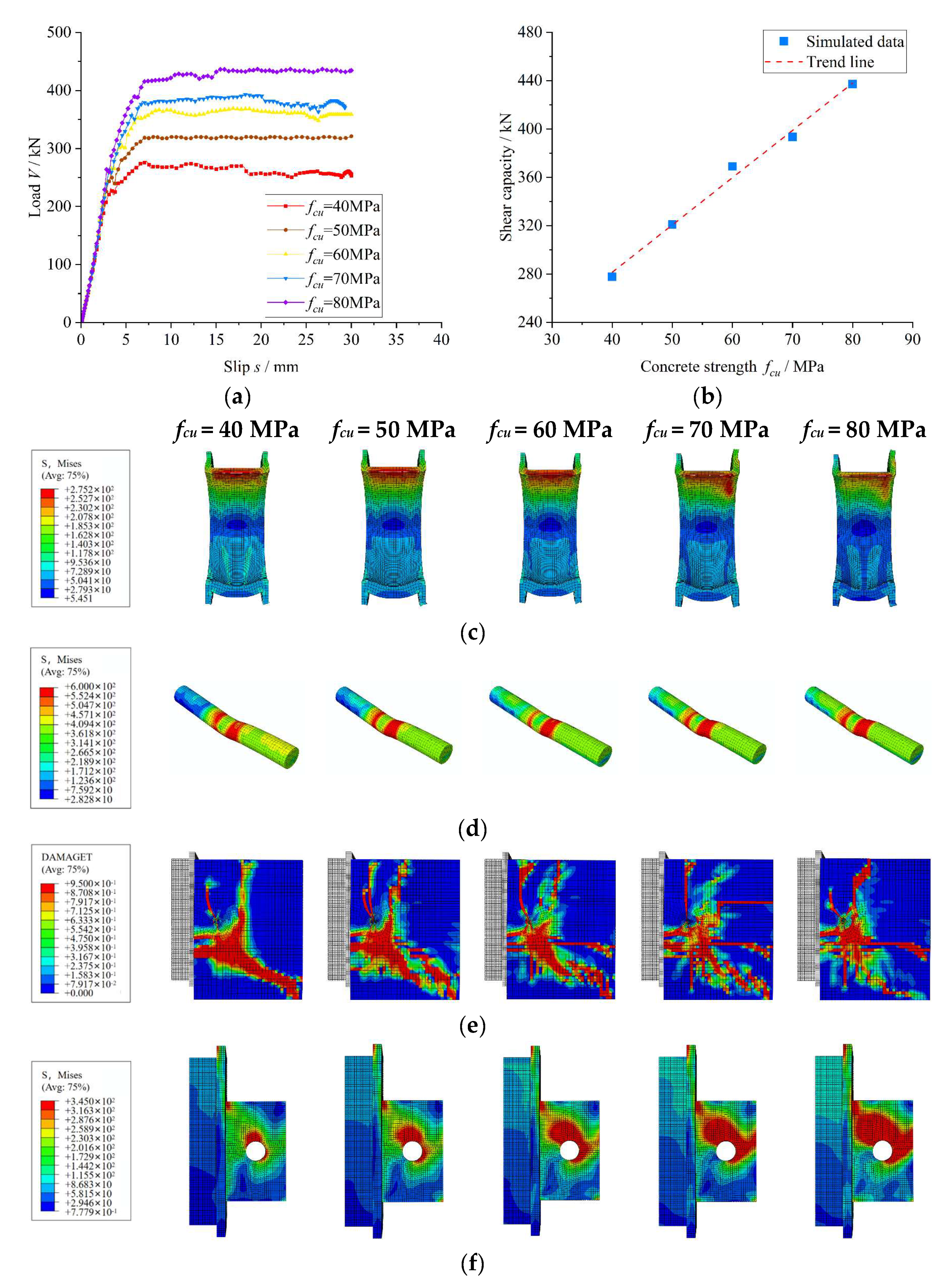
Figure 9 illustrates the load–slip curves and stress distribution characteristics of the Twin-PBL rubber-ring shear connector under varying concrete strengths. With all other model dimensions held constant, the compressive strength of the concrete slab increases from 40 MPa to 50 MPa, 60 MPa, 70 MPa, and 80 MPa. Consequently, the yield load (
Vy) increases by 18.3%, 28.5%, 35.3%, and 38.6%, respectively. The shear stiffness (
Ks) increases by 6.2%, 11.3%, 11.5%, and 18.1%, while the shear capacity (
Vu) improves by 15.3%, 32.8%, 41.7%, and 57.3%. These findings demonstrate that increasing the concrete strength significantly enhances the shear performance of the Twin-PBL rubber-ring shear connector.
It is noteworthy that the stress distribution characteristics (
Figure 9c–f) reveal a significant intensification of stress concentration within the rubber ring as the concrete strength increases. Simultaneously, stress concentration in the perforated rebar and perfobond steel plate also increases, while the tensile damage area in the concrete slab diminishes. The increase in concrete strength enhances the shear bearing capacity of the concrete dowel, enabling it to withstand greater loads before failure, thereby improving the overall shear capacity of the connector. The increased strength of the concrete surrounding the perfobond steel plate allows the slab to endure larger stresses transmitted by the plate, hence reducing its likelihood of failure. Moreover, the stress distribution in the perforated rebar and perfobond steel plate exhibits a pronounced concentration effect. This phenomenon can be attributed to the improved strength of the concrete dowel, which facilitates greater load-sharing between the dowel and the perforated rebar at higher load levels and also necessitates that the perfobond steel plate transfer greater shear forces.
5.4. Impact of Perforated Rebar Strength
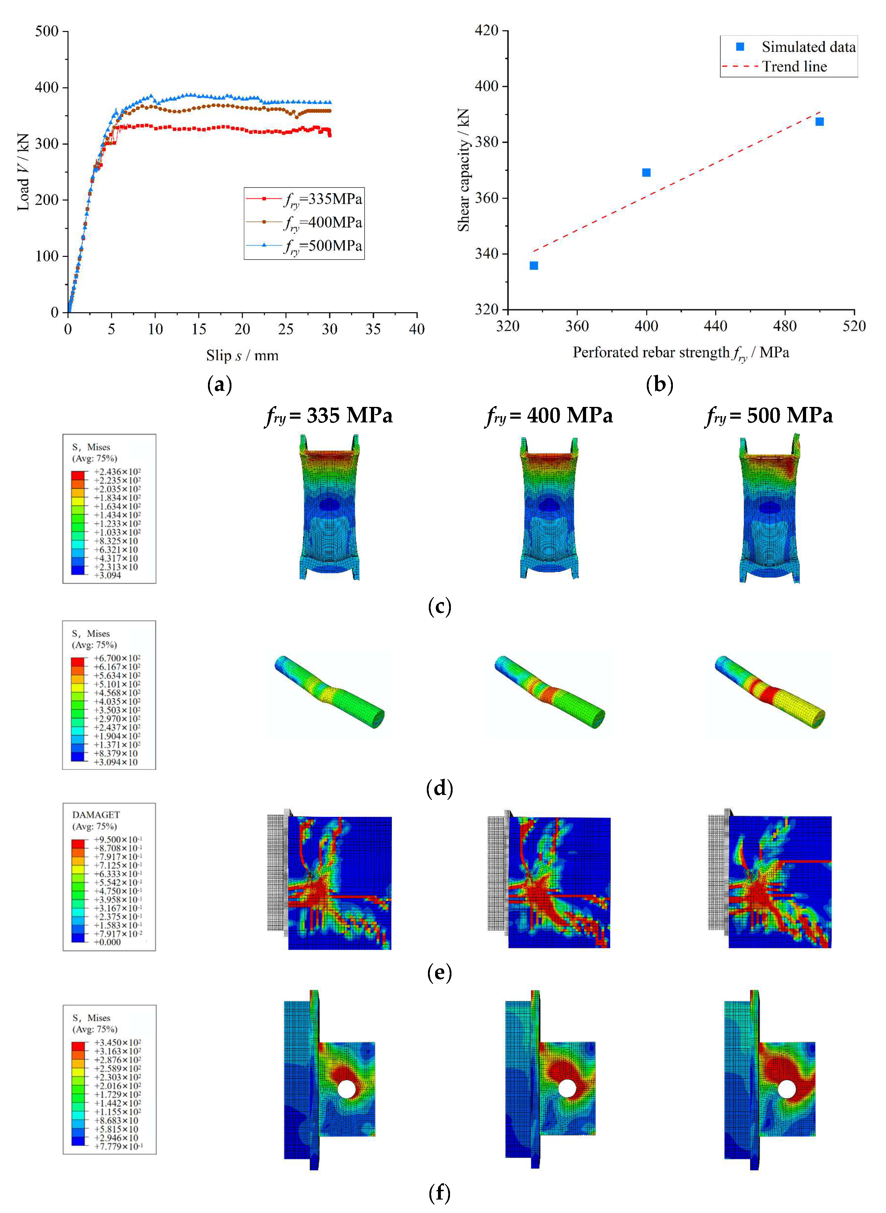
Figure 10 shows the load–slip curves and stress distribution characteristics of the Twin-PBL rubber-ring shear connector under varying strengths of perforated rebar. When the strength of the perforated rebar increases from 335 MPa to 400 MPa and 500 MPa, the yield load, shear stiffness, and shear capacity of the connector all improve, showing a positive correlation with the rebar strength. Specifically, the yield load (
Vy) increases by 8.2% and 9.6%, respectively. The shear stiffness (
Ks) increases by 0.8% and 2.0%, while the shear capacity (
Vu) increases by 9.9% and 15.37%. These results confirm that enhancing the strength of the perforated rebar significantly improves the shear performance of the Twin-PBL rubber-ring shear connector.
The stress distribution characteristics (
Figure 10c–f) demonstrate that increasing the strength of the perforated rebar intensifies stress concentration within the rubber ring. At the same time, stress becomes increasingly localized in both the perforated rebar and the perfobond steel plate, leading to an expansion of the tensile damage zone within the concrete slab. This behavior arises because the enhanced strength of the perforated rebar improves its load-bearing capacity while concurrently reducing its shear deformation capability, thereby delaying structural failure to higher load levels. However, the reduced shear deformation capacity causes the concrete dowel to fail at lower load thresholds, which in turn increases the compressive stress exerted on the concrete slab by the perforated rebar, resulting in significant tensile damage. As the load transfer through the perfobond steel plate intensifies, stress concentration progressively develops.
5.5. Impact of Perfobond Steel Plate Strength
Figure 11 presents the load–slip curves and stress distribution characteristics of Twin-PBL rubber-ring shear connectors with varying perfobond steel plate strengths. The yield load (
Vy) increases by 13.0%, 14.9%, 15.6%, and 20.2% for connectors incorporating perfobond steel plates with strengths of 345 MPa, 390 MPa, 420 MPa, and 460 MPa, respectively, as the strength of the perfobond steel plate is varied while the dimensions of all model components remain unchanged. The shear stiffness (
Ks) increases by 1.7%, 1.6%, 1.5%, and 1.1%, while the shear capacity (
Vu) increases by 13.36%, 11.7%, 11.4%, and 14.3%, respectively. These findings suggest that the influence of perfobond steel plate strength on the shear performance of the Twin-PBL rubber-ring shear connectors is subject to certain limitations.
The stress distribution characteristics (
Figure 11c–f) indicate that the stresses in the rubber ring and perforated rebar remain relatively stable with increasing steel plate strength. Similarly, the tensile damage distribution on the concrete slab remains largely unchanged, except in the case of the 235 MPa steel plate. The stress in the steel plate is primarily concentrated above the openings and away from the steel beams, with this concentration becoming more pronounced as the strength increases. Notably, the high-strength steel plate does not fully yield, and yielding occurs only at the openings. The deformation levels of the steel plate and perforated rebar indicate that the deformation capacity of the steel plate decreases with increasing strength, leading to connector failure mostly due to shear in the perforated rebar.
6. Prediction Formula
6.1. Previous Expressions
To mitigate the influence of end-bearing pressure on the shear performance of the Twin-PBL rubber-ring shear connector, a 50 mm gap was introduced in the slip direction of the perfobond steel plate in parametric study. Assuming that only the friction between the concrete slab and the rigid base exists, all other contact surfaces of the model are frictionless. The following section reviews some important previous studies and associated equations.
Hosaka et al. conducted a classification analysis of connectors by evaluating the presence or absence of perforated rebar in the holes of the perfobond steel plate. Equation (7) was proposed to estimate the shear capacity of connectors without perforated rebar in the holes, while Equation (8) was developed for connectors that include perforated rebar in the holes [
28].
The parameters considered include the thickness of the perfobond steel plate (tp), the concrete compressive strength (fc), the rebar hole diameter (dr), and the ultimate tensile strength (fru).
Zheng et al. investigated connectors composed of perfobond steel plates with notches and proposed Equation (9) to evaluate their shear capacity. A parametric analysis was performed on the notched perfobond steel plate connectors to examine the restraining effect of the perforated rebar on concrete, incorporating both pull-out tests and numerical simulations [
29].
In this context, Vu denotes the shear load capacity of a single perfobond steel plate. fry and fsy represent the yield strengths of the perforated rebar and the steel plate, respectively, both expressed in MPa. The parameters fc and dr denote the concrete compressive strength and the diameter of the perforated rebar, respectively. Specifically, γn is a coefficient that accounts for the effect of the number of holes in the steel plate, defined as γn = np−0.22, where np is the number of holes. γe is a coefficient that considers the influence of hole spacing on the steel plate, defined as γe = 1 + 0.002·(ep − 200) ≤ 1, where ep denotes the hole spacing.
6.2. Proposed Formula for Shear Capacity
Previous studies indicate that the shear capacity of the conventional Twin-PBL shear connectors is primarily contributed by the perforated rebars, concrete dowels, rubber rings, and perfobond steel plates. Given that the rubber ring is a low-stiffness material with limited load-bearing capacity, the shear capacity of the Twin-PBL rubber-ring shear connector is expressed as shown in Formula (10).
Vts denotes the shear capacity provided by the perforated rebar (in N); Vct denotes the shear capacity provided by the concrete dowel (in N); Vps denotes the shear capacity provided by the perfobond steel plate (in N).
Therefore, Equations (11) and (12) can be used to determine the shear capacity of the Twin-PBL rubber-ring shear connector.
Vu denotes the shear capacity of an individual perfobond steel plate (in N); Ats denotes the cross-sectional area of the perforated rebar, whereas Act represents the cross-sectional area of the concrete dowel. Aps denotes the contact area between the perfobond steel plate and the dowel; dp refers to the diameter of the perforation in the perfobond steel plate; fc denotes the compressive strength of concrete; fry represents the yield strength of the perforated rebar; tp denotes the thickness of the perfobond steel plate; fsy indicates the yield strength of the perfobond steel plate; dr signifies the diameter of the perforated rebar; tr denotes the thickness of the rubber ring; and D1, D2, and D3 are the three constant coefficients.
Nonlinear regression analysis of the findings from the finite element parameter analysis indicates that the best fitting performance of Equation (12) is achieved when the coefficients are set to
D1 = 1.16,
D2 = 1.71, and
D3 = 0.18. Equation (13) is derived to evaluate the shear capacity of an individual perfobond steel plate in the Twin-PBL rubber-ring shear connector.
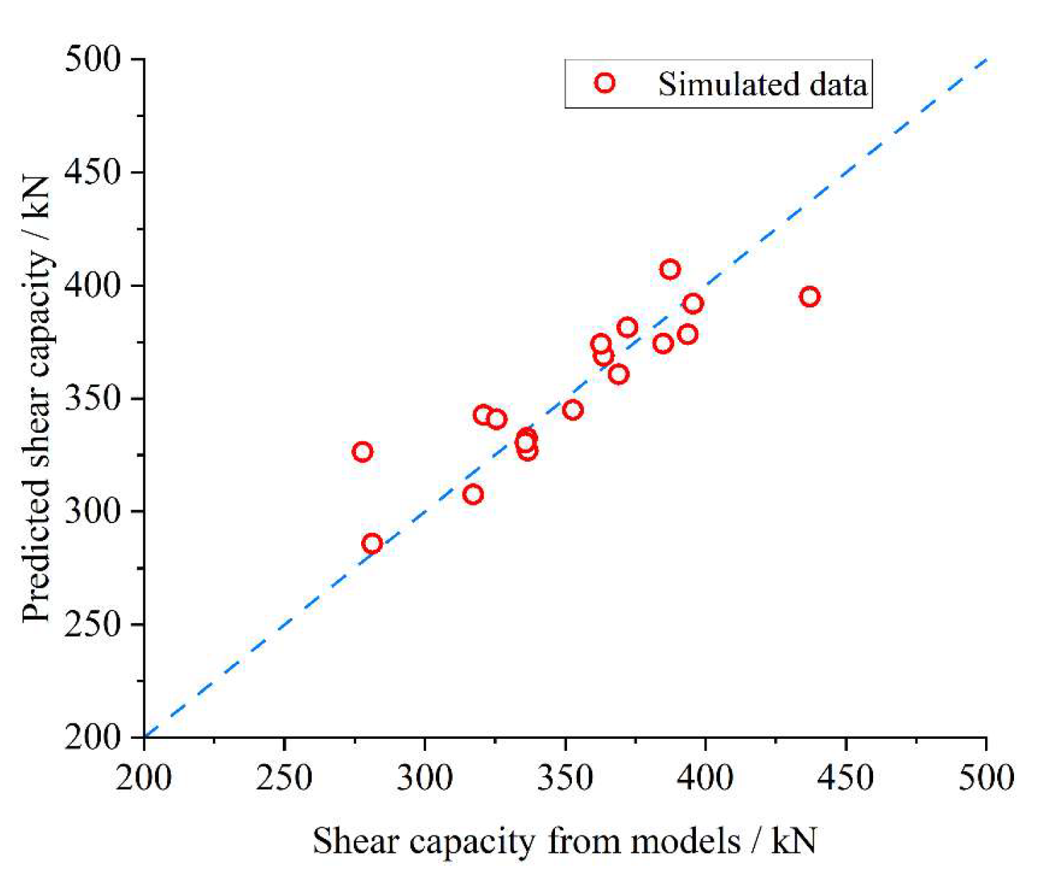
Figure 12 presents a comparative analysis and validation of the shear capacity predicted by Equation (13) against the results obtained from finite element simulations. The mean and standard deviation of the ratio of predicted values to simulated values are 1.01 and 0.0556, respectively, demonstrating a strong agreement between theoretical predictions and numerical modeling outcomes.
As shown in
Figure 12, the predicted results exhibit excellent consistency with the finite element simulation outcomes, which provides a reliable reference for subsequent experimental validation and the broader application of the Twin-PBL rubber-ring shear connector.
7. Conclusions
This study investigates Twin-PBL rubber-ring shear connectors through a series of numerical simulations. First, the connector was designed. Subsequently, 23 different finite element models were established for comparative analysis based on the finite element simulation and analysis methodology described in reference [
14]. Further, the shear performance of Twin-PBL rubber-ring shear connector as well as the factors affecting this performance were simulated and analyzed in detail. Finally, new equations for calculating the performance of the Twin-PBL rubber-ring shear connector were deduced. The following conclusions were drawn:
A comparative evaluation of the mechanical performance between the Twin-PBL rubber-ring shear connector and its conventional counterpart reveals that the inclusion of a 4 mm-thick rubber ring results in a slight 7.5% reduction in shear capacity, while simultaneously causing a significant 71% decrease in shear stiffness. This suggests that the incorporation of a low-stiffness rubber component primarily governs the reduction in structural stiffness, whereas its influence on the ultimate shear resistance is relatively minor.
A comparison of the mechanical performance between the Twin-PBL rubber-ring shear connector and the conventional connector demonstrates that the use of a 4 mm-thick rubber ring increases the yield slip of the former to 183.0% of that of the latter. This finding highlights the critical role of the rubber component in improving the deformation capacity of the shear connector system while maintaining structural integrity, as it significantly enhances ductility through its integration.
Finite element parametric studies on rubber rings with varying thicknesses indicate that the strategic integration of elastomeric components effectively mitigates stress concentrations at the perforation regions of the connectors. The enhanced deformability and optimized shear stress redistribution patterns observed in the numerical simulations show that rubber interlayers not only improve structural flexibility but also promote more uniform load transfer mechanisms, thereby fundamentally modifying the mechanical response characteristics of the connector system.
The analytical results demonstrate that parameters such as the diameter and tensile strength of the perforated rebars, the thickness of the rubber rings, and the compressive strength of the concrete have a significant impact on the shear load capacity and shear strength of the Twin-PBL rubber-ring shear connectors. Variations in these parameters can directly influence the performance of the connectors under shear loading, thereby affecting the overall safety and stability of the structural system. An increase in the diameter and tensile strength of the perforated rebars generally enhances the shear capacity of the connectors, whereas the thickness of the rubber rings primarily affects their deformation characteristics. Moreover, as a key structural material, higher concrete strength can considerably improve the shear performance of the connectors. However, the research results suggest that the strength of the perfobond steel plates exerts a relatively minor influence.
A shear capacity prediction formula specifically designed for the Twin-PBL rubber-ring shear connector is developed through a comprehensive review of existing shear capacity calculation methods and their derivation processes, combined with finite element parametric analysis results and the observed failure mechanisms of the connectors. The computed results exhibit a high degree of consistency with the finite element simulations, offering a dependable reference for further study and practical engineering applications.
In conclusion, this research employs the finite element method to investigate the shear performance of the Twin-PBL rubber-ring shear connector. Extensive simulations and analyses suggest that the Twin-PBL rubber-ring shear connector exhibits relatively low initial stiffness. This study identifies key factors influencing the shear performance of the connector, enabling the determination of an optimal combination of connector properties. The proposed method for predicting the shear bearing capacity of the Twin-PBL rubber-ring shear connector may provide valuable insights and reliable estimations for its anticipated performance in practical engineering applications.
Author Contributions
J.W. proposed the research project, designed the shear connector, and wrote the initial manuscript; P.C. established finite element models, performed numerical simulations and data analyses; Q.H. carried out text proofreading and project administration. All authors have read and agreed to the published version of the manuscript.
Funding
The study was sponsored by Project of General Scientific Research Program of Department of Education, Zhejiang Province (Y202250206).
Data Availability Statement
The data used to support the results of this study are available from the corresponding author upon request.
Acknowledgments
The authors would like to acknowledge Zhejiang Department of Education for the funding support.
Conflicts of Interest
The authors declare that they have no conflicts of interest.
References
- He, J.; Liu, Y.; Pei, B. Experimental Study of the Steel-Concrete Connection in Hybrid Cable-Stayed Bridges. J. Perform. Constr. Facil. 2014, 28, 559–570. [Google Scholar] [CrossRef]
- Zhang, Q.; Jia, D.; Bao, Y.; Cheng, Z.; Xiao, L.; Bu, Y. Internal Force Transfer Effect-Based Fatigue Damage Evaluation for PBL Shear Connector Groups. J. Constr. Steel Res. 2018, 148, 469–478. [Google Scholar] [CrossRef]
- Zheng, S.; Zhao, C.; Liu, Y. Analytical Model for Load–Slip Relationship of Perfobond Shear Connector Based on Push-Out Test. Materials 2018, 12, 29. [Google Scholar] [CrossRef] [PubMed]
- Kim, Y.-H.; Kang, J.-Y.; Kim, S.-H.; Kim, D.-J. Structural Performance of Steel Pile Caps Strengthened with Perfobond Shear Connectors under Lateral Loading. Appl. Sci. 2016, 6, 317. [Google Scholar] [CrossRef]
- Xue, D.; Liu, Y.; He, J.; Ma, B. Experimental Study and Numerical Analysis of a Composite Truss Joint. J. Constr. Steel Res. 2011, 67, 957–964. [Google Scholar] [CrossRef]
- Zheng, S.; Liu, Y.; Yoda, T.; Lin, W. Parametric Study on Shear Capacity of Circular-Hole and Long-Hole Perfobond Shear Connector. J. Constr. Steel Res. 2016, 117, 64–80. [Google Scholar] [CrossRef]
- Gu, J.-C.; Liu, D.; Deng, W.-Q.; Zhang, J.-D. Experimental Study on the Shear Resistance of a Comb-Type Perfobond Rib Shear Connector. J. Constr. Steel Res. 2019, 158, 279–289. [Google Scholar] [CrossRef]
- Zhang, Q.; Pei, S.; Cheng, Z.; Bao, Y.; Li, Q. Theoretical and Experimental Studies of the Internal Force Transfer Mechanism of Perfobond Rib Shear Connector Group. J. Bridge Eng. 2017, 22, 04016112. [Google Scholar] [CrossRef]
- Liu, Y.; Xin, H.; Liu, Y. Load Transfer Mechanism and Fatigue Performance Evaluation of Suspender-Girder Composite Anchorage Joints at Serviceability Stage. J. Constr. Steel Res. 2018, 145, 82–96. [Google Scholar] [CrossRef]
- Fang, Z.; Wu, J.; Xu, X.; Ma, Y.; Fang, S.; Zhao, G.; Jiang, H. Grouped Rubber-Sleeved Studs–UHPC Pocket Connections in Prefabricated Steel–UHPC Composite Beams: Shear Performance under Monotonic and Cyclic Loadings. Eng. Struct. 2024, 305, 117781. [Google Scholar] [CrossRef]
- Zhang, Y.; Zhu, J.; Wu, L.; Lin, H.; Fang, Z.; Cen, Z.; Yang, Y.; Fang, S. Experimental and Numerical Analyses on the Shear Behavior of Grouped Single-Embedded-Nut High-Strength Bolts in Steel–Ultra-High-Performance Concrete Composite Slabs. J. Build. Eng. 2024, 86, 108829. [Google Scholar] [CrossRef]
- Nie, J.-G.; Li, Y.-X.; Tao, M.-X.; Nie, X. Uplift-Restricted and Slip-Permitted T-Shape Connectors. J. Bridge Eng. 2015, 20, 04014073. [Google Scholar] [CrossRef]
- Xu, X.; Liu, Y.; He, J. Study on Mechanical Behavior of Rubber-Sleeved Studs for Steel and Concrete Composite Structures. Constr. Build. Mater. 2014, 53, 533–546. [Google Scholar] [CrossRef]
- Liu, Y.; Xin, H.; Liu, Y. Experimental and Analytical Study on Shear Mechanism of Rubber-Ring Perfobond Connector. Eng. Struct. 2019, 197, 109382. [Google Scholar] [CrossRef]
- Xu, Y.; He, S.; Guan, P.; Mosallam, A.S.; Zeng, J.; Wan, Z. Shear Behavior of Flexible-Sleeve Perfobond Strip Connectors: Experimental and Analytical Studies. Eng. Struct. 2022, 264, 114380. [Google Scholar] [CrossRef]
- Khatir, A.; Capozucca, R.; Khatir, S.; Magagnini, E.; Le Thanh, C.; Riahi, M.K. Advancements and Emerging Trends in Integrating Machine Learning and Deep Learning for SHM in Mechanical and Civil Engineering: A Comprehensive Review. J. Braz. Soc. Mech. Sci. Eng. 2025, 47, 419. [Google Scholar] [CrossRef]
- Appavuravther, E.; Vandoren, B.; Henriques, J. Analytical and Numerical Investigation of Adhesively Bonded Perfobond Shear Connectors for Timber-Concrete Composite Floors. Structures 2024, 70, 107582. [Google Scholar] [CrossRef]
- Asgari, A.; Ranjbar, F.; Bagheri, M. Seismic Resilience of Pile Groups to Lateral Spreading in Liquefiable Soils: 3D Parallel Finite Element Modeling. Structures 2025, 74, 108578. [Google Scholar] [CrossRef]
- Bagheri, M. Seismic Resilience Assessment of RC Superstructures on Long–Short Combined Piled Raft Foundations: 3D SSI Modeling with Pounding Effects. Structures 2025, 81, 110176. [Google Scholar] [CrossRef]
- Liu, Y.; Yang, H.; Luan, L.; Xu, X.; Liu, Y.; Du, X. Three Failure Modes of High-Strength Steel (HSS) Perfobond Connector Embedded in UHPC. Eng. Struct. 2023, 286, 116147. [Google Scholar] [CrossRef]
- Liu, Y.; Liu, Y.; Xin, H.; Tian, H.; Wei, J. Numerical Study on Shear Performance of a New Perfobond Connector with Controllable Stiffness. Adv. Mater. Sci. Eng. 2020, 2020, 5384701. [Google Scholar] [CrossRef]
- Sun, L.; Liu, Y.; Wang, H.; Shi, F.; Liu, J.; Jiang, L. Tensile Stiffness of Perfobond Rib Connectors in Steel–Concrete Composite Pylon of Bridges. Eng. Struct. 2023, 284, 115931. [Google Scholar] [CrossRef]
- Sun, L.; Liu, Y.; Shi, F.; Wang, H. Pull-out Performance of Perfobond Rib Connectors in Steel High-Strength Concrete Composite Bridge Pylons. Constr. Build. Mater. 2023, 366, 130205. [Google Scholar] [CrossRef]
- Walraven, J.C. Model Code 2010-Final Draft: Volume 1; Fib Fédération Internationale Du Béton: Lausanne, Switzerland, 2012; Volume 65. [Google Scholar]
- Nguyen, H.T.; Kim, S.E. Finite Element Modeling of Push-out Tests for Large Stud Shear Connectors. J. Constr. Steel Res. 2009, 65, 1909–1920. [Google Scholar] [CrossRef]
- Comité Euro-International du Béton. CEB-FIP Model Code 1990: Design Code; Thomas Telford Publishing: London, UK, 1993. [Google Scholar]
- Hordijk, D.A. Tensile and Tensile Fatigue Behaviour of Concrete; Experiments, Model-Ling and Analyses. Heron 1992, 37, 3–79. [Google Scholar]
- Hosaka, T.; Mitsuki, K.; Hiragi, H.; Ushijima, Y.; Tachibana, Y.; Watanabe, H. An Experimental Study on Shear Characteristics Ofperfobond Strip and Its Rational Strength Equations. J. Struct. Eng. JSCE 2000, 46, 1593–1604. [Google Scholar]
- Zheng, S.; Liu, Y.; Liu, Y.; Zhao, C. Experimental and Numerical Study on Shear Resistance of Notched Perfobond Shear Connector. Materials 2019, 12, 341. [Google Scholar] [CrossRef]
| Disclaimer/Publisher’s Note: The statements, opinions and data contained in all publications are solely those of the individual author(s) and contributor(s) and not of MDPI and/or the editor(s). MDPI and/or the editor(s) disclaim responsibility for any injury to people or property resulting from any ideas, methods, instructions or products referred to in the content. |
© 2025 by the authors. Licensee MDPI, Basel, Switzerland. This article is an open access article distributed under the terms and conditions of the Creative Commons Attribution (CC BY) license (https://creativecommons.org/licenses/by/4.0/).
