1. Introduction
With the rapid expansion of infrastructure construction and underground space utilization, understanding the mechanical behavior of concrete–rock composite structures has become pivotal for ensuring the safety of railways, tunnels, dams, and slopes [
1,
2,
3,
4,
5]. Natural rock masses often develop complex fracture networks due to geological processes, substantially undermining their load-bearing capacity. To compensate, concrete is used to form concrete–fractured rock composites (CFRCs), in which the concrete must work synergistically with the fractured rock. In fault zones or high-stress regions, stress concentrations and stiffness mismatches at the concrete–rock interface frequently induce debonding or shear slip, dramatically raising the risk of structural failure. Moreover, fracture geometry, particularly the dip angle, alters the internal stress transfer pathways in the rock. This change further influences the composite’s failure modes [
6]. By optimizing composite design for durability and minimizing over-excavation, we can lower the embodied carbon of support structures and reduce the energy consumption associated with maintenance and repair over their service life. Therefore, elucidating the mechanical response mechanisms of CFRCs is critical for optimized design and long-term safety. In addition, understanding these mechanisms aligns with the broader goal of reducing the environmental footprint of engineering construction [
7].
Several laboratory investigations have been conducted on the mechanical behavior of concrete–rock composites [
4,
8,
9,
10,
11]. For example, Liu et al. [
3] performed uniaxial compression and acoustic emission tests on rock–concrete specimens at four temperatures (20 °C, 40 °C, 60 °C, and 80 °C) and six interface inclinations (15°, 30°, 45°, 60°, 75°, and 90°). Wang et al. [
2] used nuclear magnetic resonance (NMR) and scanning electron microscopy (SEM) alongside a self-developed, high-precision, saturated shear testing apparatus to comprehensively examine frost–thaw damage and shear behavior in concrete–rock composite structures. Wu et al. [
12] employed a SANS electro-hydraulic servo universal testing machine to carry out three-point bending tests on concrete–rock composite samples with six different interface dip angles. Zhang et al. [
13] quantified the effects of joint roughness coefficients (JRC values ranging from 4 to 20) and interface geometries (wave-shaped, triangular, and stepped) on the dynamic splitting performance of rock–concrete composites. Collectively, these studies have greatly enriched our understanding of concrete–rock composite materials.
Extensive experimental studies have provided rich data and insights into the failure mechanisms of concrete–rock composites. However, systematic investigation of microscale crack evolution and interface interactions remains limited. Performance under extreme environmental conditions is also constrained by experimental methods and associated costs. Numerical simulation, particularly the discrete element method (DEM), has garnered significant attention for its ability to serve as a virtual laboratory that bridges microscale processes and macroscale responses [
14,
15,
16,
17]. DEM has successfully modeled fracture propagation in fractured rock, revealing how fracture inclination influences peak strength and failure modes [
18]. In the field of concrete, numerous studies have employed the discrete element method to analyze its microscopic crack initiation and propagation, damage evolution, and dynamic failure characteristics [
19,
20,
21,
22]. However, research on concrete–rock composites still faces notable limitations. Most existing studies neglect the coupled effects of pre-existing fractures, in situ stress, and layered interfaces. In addition, the majority focus on macroscopic mechanical responses, rather than examining the micromechanisms of crack initiation and propagation. These gaps hinder the accurate assessment of long-term stability in composite structures under current design codes.
To address these gaps, this study employs the discrete element method to, for the first time, systematically investigate the influence of fracture geometry and confining pressure on the mechanical behavior of CFRCs. A heterogeneous composite model is constructed by calibrating the micromechanical parameters of both the rock and concrete phases. The model’s response under varying confining pressures is then simulated. This allows elucidation of the crack–growth mechanisms between the concrete and the rock. By tracking both tensile and shear crack evolution, the progressive failure behavior of the composite is quantitatively characterized. The results of this research will advance the high-precision design and intelligent monitoring of CFRC structures.
2. Numerical Simulation Methods
2.1. Simulation Software
The discrete element software used in this study is the particle flow code 6.0 (PFC 6.0). PFC is a numerical simulation tool based on the discrete element method that was developed by Itasca Consulting Group, Inc. (Minneapolis, MN, USA), and is specifically designed for analyzing the mechanical behavior of discontinuous media, such as geomaterials and granular assemblies. Its core concept is to discretize the material into an assembly of rigid particles and to compute the interaction forces and displacement evolution between particles via Newton’s laws of motion, thereby revealing the material’s macroscopic mechanical response. PFC is available in two- and three-dimensional versions (PFC2D and PFC3D) and is widely used in geotechnical engineering, mining engineering, and materials science, with strengths in simulating large deformations, particle breakage, and discontinuous interface problems [
23,
24,
25,
26,
27].
The PFC modeling workflow comprises the following key steps: generate a particle assembly based on particle size distribution, porosity, and other parameters, and define boundary conditions (e.g., wall constraints); choose an appropriate contact mode, such as the linear contact model, the parallel bond model (PBM), or the rolling-resistant contact model based on material characteristics, and specify micromechanical parameters, including normal and tangential stiffness and friction coefficients between particles; apply loads (e.g., displacement-controlled or stress-controlled) and perform time-step integration to compute particle motion; and extract data on macroscopic stress–strain behavior, particle displacement fields, and microcrack distributions for interpretation.
2.2. Contact Mode
In this study, a composite model of concrete and fractured rock was developed in which the intact concrete and rock matrix were modeled using the PBM, while pre-existing fracture or interface surfaces were represented by the smooth-joint model (SJM), thereby accurately reproducing both “bonded–fracture” and “friction–opening” mechanical behaviors (
Figure 1).
PBM is a classic method in Itasca’s PFC for simulating cementation between particles [
15,
28]. At each particle contact, a finite-size, linear, spring–bond unit is placed in parallel so that it is capable of transmitting normal and shear forces as well as bending moments and torques. This allows the capture of a material’s full elastic–strength response before and after failure. When stress within the bond exceeds the predefined normal or shear strength thresholds, the bond breaks, and the model degrades to a frictional, linear spring contact, thus simulating crack initiation and propagation. During parameter calibration, the ratio of microscopic normal-to-shear stiffness
/
is typically set equal to the macroscopic ratio
, where
is the macroscopic Young’s modulus,
is the macroscopic shear modulus, and
is Poisson’s ratio. This ensures that the simulated elastic and shear moduli accurately reflect the material’s bulk properties.
Numerous application studies have demonstrated PBM’s ability to reproduce the strength and fracture mechanisms of rock and concrete materials [
29,
30]. For example, Zhu et al. [
31] employed PBM to simulate a concrete–rock composite, systematically analyzing its energy evolution and crack propagation. Furthermore, the official PFC tutorial uses PBM as the foundational example for generating parallel-bonded materials, highlighting its broad applicability in modeling both continuous bulk media and discrete crack networks.
The SJM is specifically designed to simulate “friction–opening” behavior on predefined discontinuities such as faults or bedding planes [
32]. It imposes a globally consistent joint orientation at particle contacts, allowing the interface to open once the normal tensile threshold has been exceeded and to slip according to Coulomb’s law of friction, while also accounting for dilation effects. Under bonded conditions, the interface behaves linearly elastically. When shear or tensile forces surpass the interface strength, the model automatically transitions to an unbonded contact governed solely by friction and dilation, thereby accurately capturing the sliding and opening mechanisms of fracture surfaces under load.
Studies have shown that combining PBM and SJM within a single numerical framework enables simultaneous treatment of interparticle bond failure and interfacial frictional sliding [
33]. For instance, in synthetic rock mass (SRM) models, Mas Ivars et al. [
34] used PBM to reproduce matrix integrity and SJM to capture structural surface instability, successfully predicting scale effects and anisotropic responses in rock. In mining blast simulations, SJM is often used to model blast-induced opening and slip along discontinuities, yielding more reliable predictions of fracture and energy attenuation. This combined modeling approach thus provides a robust constitutive foundation for subsequent analyses of concrete–fractured rock composite mechanics.
The main source of numerical error arises from abrupt bond breakage in PBM, which generates stress fluctuations that propagate to SJM contacts. To mitigate error accumulation, we employed small time-step integration and verified that the stress transfer across PBM–SJM interfaces remains physically consistent, without causing numerical instability or non-physical oscillations.
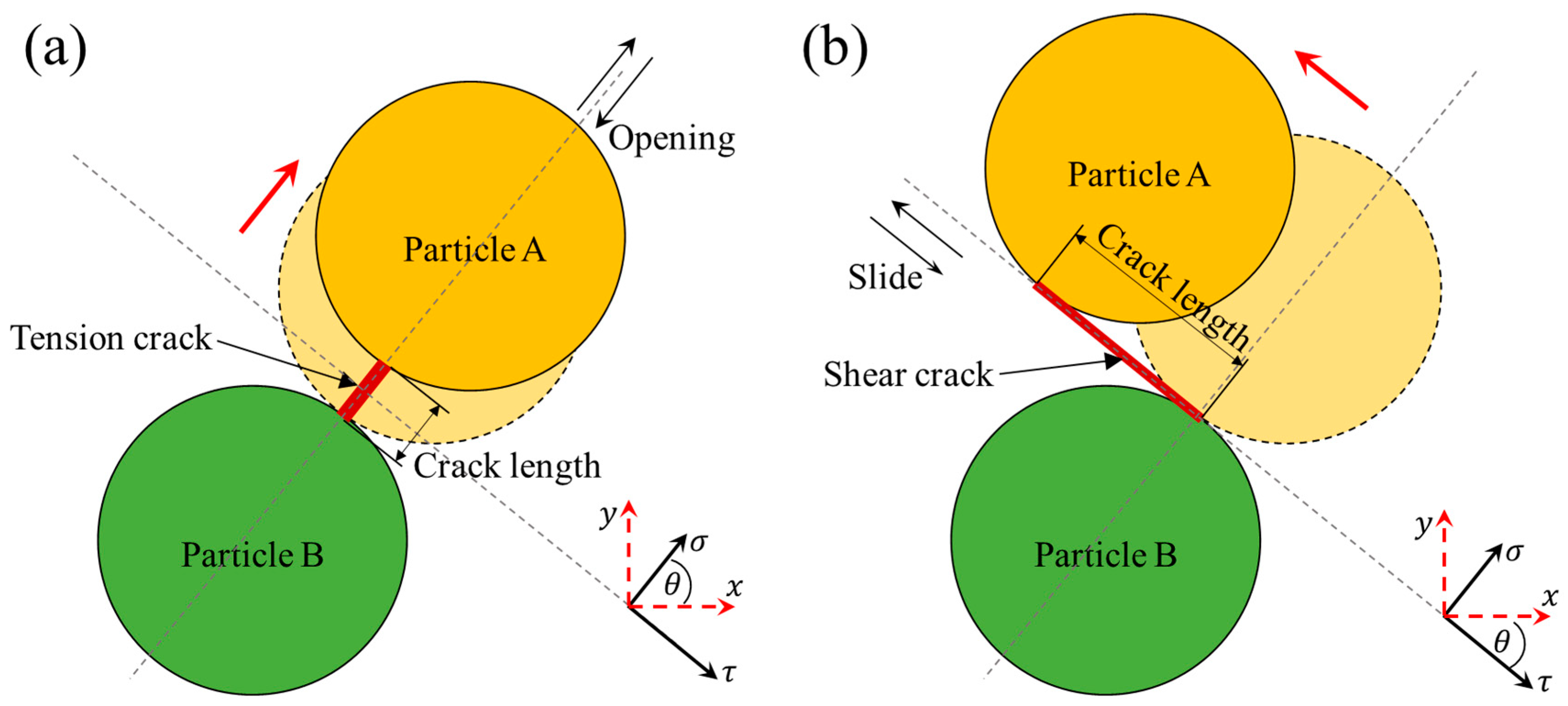
An advantage of PFC is that crack information can be obtained by user-defined functions. Microcracks are created by local stress-induced bond failure. Cracks are classified into tensile and shear cracks according to the bond failure mode, as shown in
Figure 2.
2.3. Parameter Calibration and Simulation Procedure
In DEM simulations, the calibration of micro-parameters is a critical step to ensure that a numerical model can accurately reproduce the macroscopic mechanical behavior of a material [
23,
36]. Because there is no direct analytical relationship between micro-parameters (e.g., interparticle stiffness, bond strength) and macroscopic properties (e.g., elastic modulus, compressive strength), a trial-and-error method is typically employed for parameter calibration [
37,
38,
39]. The basic calibration workflow is as follows:
- i.
Initial Parameter Assignment: Construct an initial numerical model and assign a set of preliminary micro-parameters.
- ii.
Numerical Testing: Simulate a standard mechanical test to obtain the model’s macroscopic response.
- iii.
Result Comparison: Compare the simulation results with experimental data, quantifying any discrepancies.
- iv.
Parameter Adjustment: Adjust the micro-parameters based on the magnitude and direction of these discrepancies.
- v.
Iterative Optimization: Repeat steps 2–4 until the simulated response matches the experimental observations to a satisfactory degree.
In this study, we applied the trial-and-error approach to calibrate the micro-parameters for both the rock and concrete phases. By simulating uniaxial compression tests, we adjusted the normal and shear stiffnesses and bond strengths between particles so that the model’s stress–strain curve, elastic modulus, and peak strength aligned with experimental measurements, thereby ensuring model accuracy and reliability.
The materials investigated here were our own coarse-grained granite and high-strength concrete, with experimentally measured strengths and elastic moduli of 116.8 MPa/48.2 GPa and 54.5 MPa/34.2 GPa, respectively. After calibration, the numerical model for granite exhibited a strength of 116.5 MPa and an elastic modulus of 48.1 GPa, while the concrete model showed values of 54.8 MPa and 34.5 GPa.
Table 1 lists the calibrated micro-parameters for the granite and concrete models,
Table 2 provides explanations for the PBM parameters, and
Table 3 lists the SJM settings.
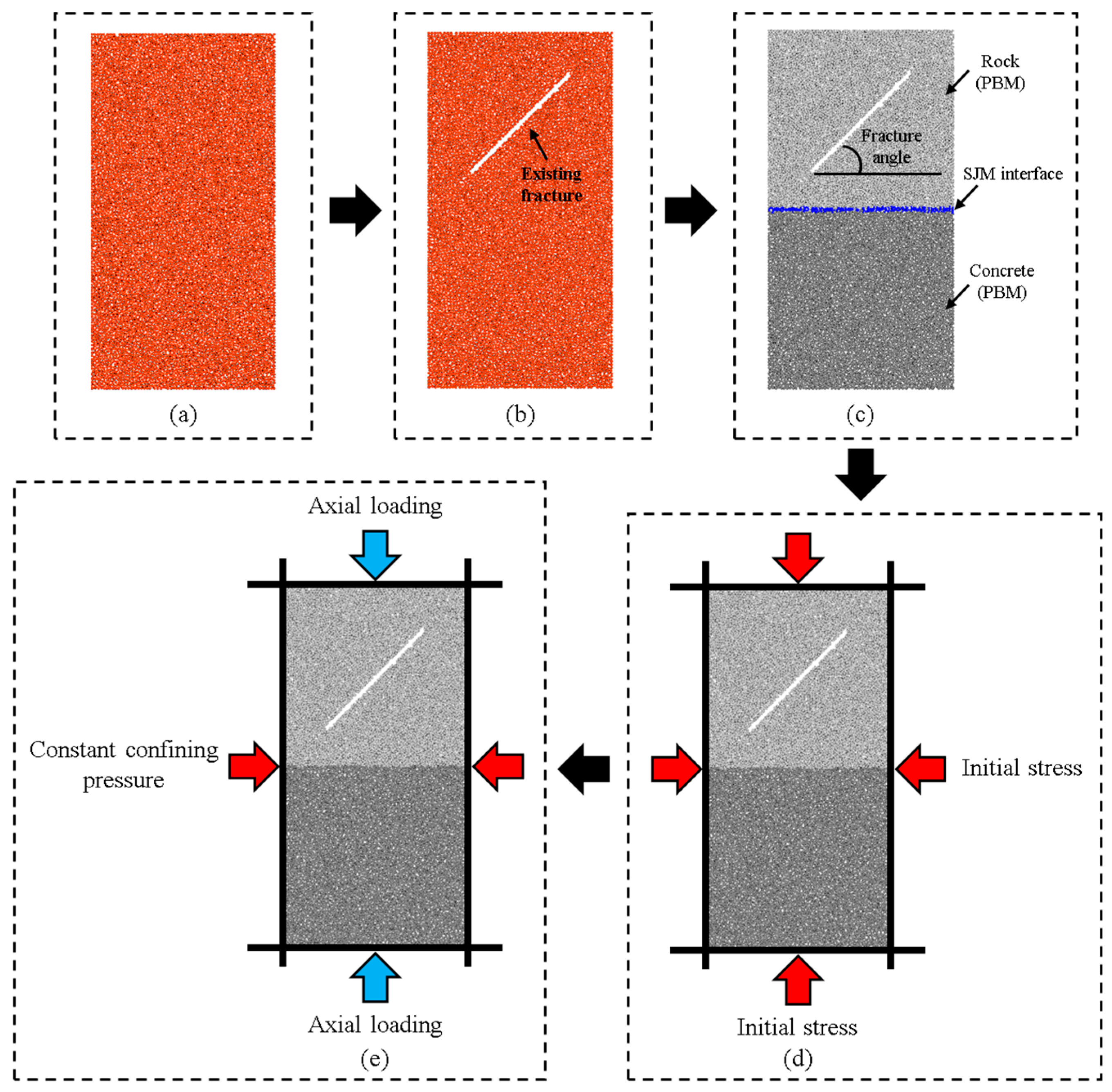
The generation steps of the numerical model are shown in
Figure 3. We generated five numerical specimens with fracture inclination angles of 0°, 22.5°, 45°, 67.5°, and 90°. The fracture angles of 0°, 22.5°, 45°, 67.5°, and 90° were selected due to their representativeness of common fracture orientations in natural geological formations. The fracture length (40 mm) and thickness (1 mm) were fixed in all models to isolate the effects of fracture inclination and confining pressure on stress distribution and crack evolution, thereby minimizing variability from the fracture size. After specimen generation, identical axial and lateral initial stresses were applied (
Figure 3d). Once the initial stress state was established, an axial load was imposed by displacing the axial walls (
Figure 3e) while the confining pressure remained constant. Each simulation was terminated when the specimen’s load-bearing capacity dropped to 40% of its peak strength. The normal stiffness of the walls was set to 1 × 10
11 N/m to approximate rigid body contact with the particles. Each model contained 7566 particles and was run on a workstation equipped with an AMD EPYC 7702 64-core processor.
Due to computational limitations, simulations were performed with ~7500 particles using CPU-based multi-core parallelization. Future large-scale simulations (>1 M particles) could employ GPU acceleration and domain decomposition, balancing higher microstructural resolution against increased wall-clock time.
3. Result and Discussion
3.1. Deformation Characteristics of CFRCs
In the study of the mechanical behavior of CFRCs, deformation characteristics are key indicators for assessing material strength and stability. Under different fracture orientations and initial stress conditions, the deformation response directly influences the failure mode and energy dissipation processes of CFRCs. Therefore, understanding these deformation characteristics is crucial for engineering design, structural safety evaluation, and long-term stability.
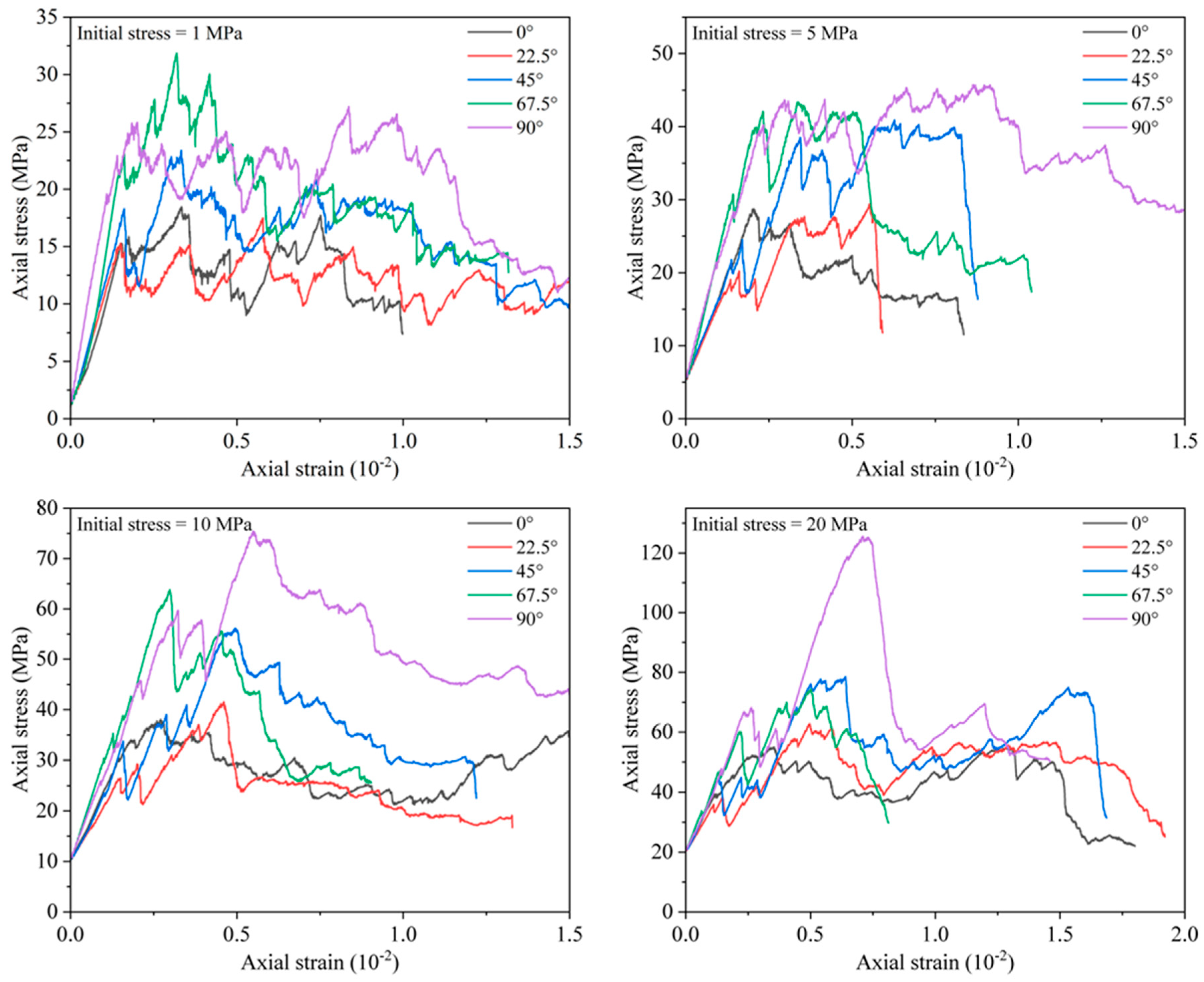
Figure 4 presents the stress–strain curves of the concrete–rock composite under various fracture angles and initial confining stresses. The mechanical behavior of the composite is evaluated based on the slope of the stress–strain curve and the peak stress, which correspond to the elastic modulus and strength, respectively. The results demonstrate that fracture inclination exerts a significant influence on the composite’s deformation behavior. When the fracture angle is small (e.g., 0° and 22.5°), the composite exhibits lower peak stress and a gentler initial slope. A small inclination allows the fracture to open along the principal stress path, promoting crack propagation in the rock matrix and thereby reducing overall stiffness and strength. As the fracture angle increases (e.g., to 67.5° and 90°), the initial slope of the stress–strain curve markedly increases, and the peak stress rises accordingly. This indicates that a larger fracture inclination directs crack extension in a manner more favorable for mobilizing the composite’s strength, thus enhancing its global stiffness and load-bearing capacity.
Moreover, the stress–strain curves display noticeable fluctuations that are not characteristic of intact rock or pure concrete. These oscillations arise from the heterogeneous propagation of cracks within the composite and the presence of pre-existing discontinuities. Non-uniform crack growth in localized zones leads to repeated stress redistributions, producing the observed undulations. In specimens with predefined fractures, irregular crack trajectories cause further local stress reallocation and micro-failures, manifesting as additional oscillations. These oscillations reflect the dynamic nature of the failure process, as cracks initiate and propagate throughout the specimen.
By analyzing these stress–strain curves, we gain deeper insight into the deformation characteristics and failure mechanisms of concrete–fractured rock composites across different conditions. These findings offer a theoretical basis for optimizing the design of composite structures, especially in fault zones or high-stress environments, thus guiding safer and more reliable engineering applications.
3.2. Strength Evolution of CFRCs
All simulations for each fracture inclination and confining pressure combination were repeated at least three times, with peak stress values varying by less than 3%, confirming the repeatability of the numerical results.
Figure 5 presents the variation of peak strength of the concrete–fractured rock composite with fracture inclination under different initial confining stress conditions.
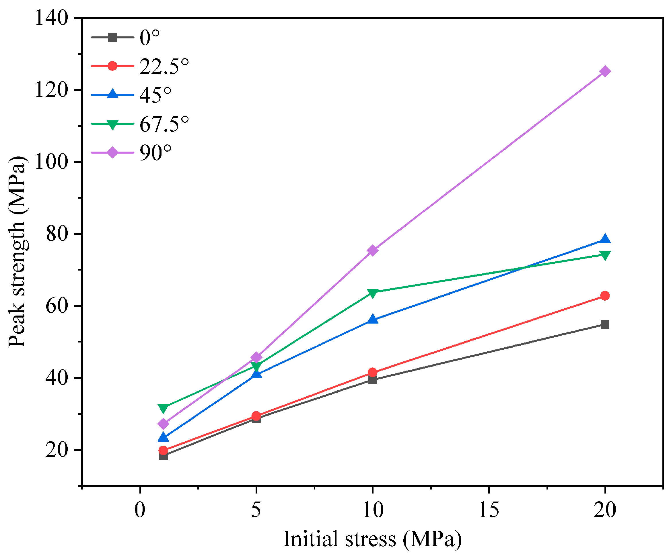
Figure 6 shows the changes in the peak strength of the composite as a function of the initial confining stress. The results indicate that fracture inclination has a significant effect on the composite’s peak strength, and that increasing the initial confining stress markedly enhances the overall strength.
As the fracture inclination increases from 0° to 90°, the composite’s peak strength rises gradually. This trend suggests that larger fracture inclinations improve the efficiency of stress transfer between the fractured rock and the concrete matrix, thereby increasing the composite’s strength. The effect of fracture inclination on strength is especially pronounced under high initial confining stress levels (10 MPa and 20 MPa), where the peak strength is considerably higher than under low-stress conditions. This demonstrates that elevated confining stress not only boosts the composite’s overall strength but also amplifies the cooperative load-bearing behavior between the fractured rock and the concrete, enabling the material to withstand greater applied stresses.
Moreover, the increase in initial confining stress further promotes strength gains at all fracture inclinations. Under low confining stresses (1 MPa and 5 MPa), the differences in composite strength across various inclinations are relatively small. In contrast, at higher confining stresses (10 MPa and 20 MPa), the strength differences become significant, indicating that the influence of the initial confining stress on composite strength intensifies as the stress level rises. This further underscores the pivotal role of confining pressure in enhancing the stability and load-bearing capacity of concrete–fractured rock composites.
In summary, both fracture inclination and initial confining stress jointly govern the strength of concrete–fractured rock composites. Increasing the fracture inclination and raising the initial confining stress both effectively enhance the composite’s strength, with the synergistic interaction between the fractured rock and the concrete becoming particularly evident under high-stress conditions.
3.3. Crack Evolution and Failure Mode of CFRCs
The evolution of microcracks is fundamental to understanding the failure mechanisms of materials. Analyzing the number and spatial distribution of cracks helps reveal the dominant failure modes in concrete–fractured rock composites and provides more accurate predictive insights for engineering design.
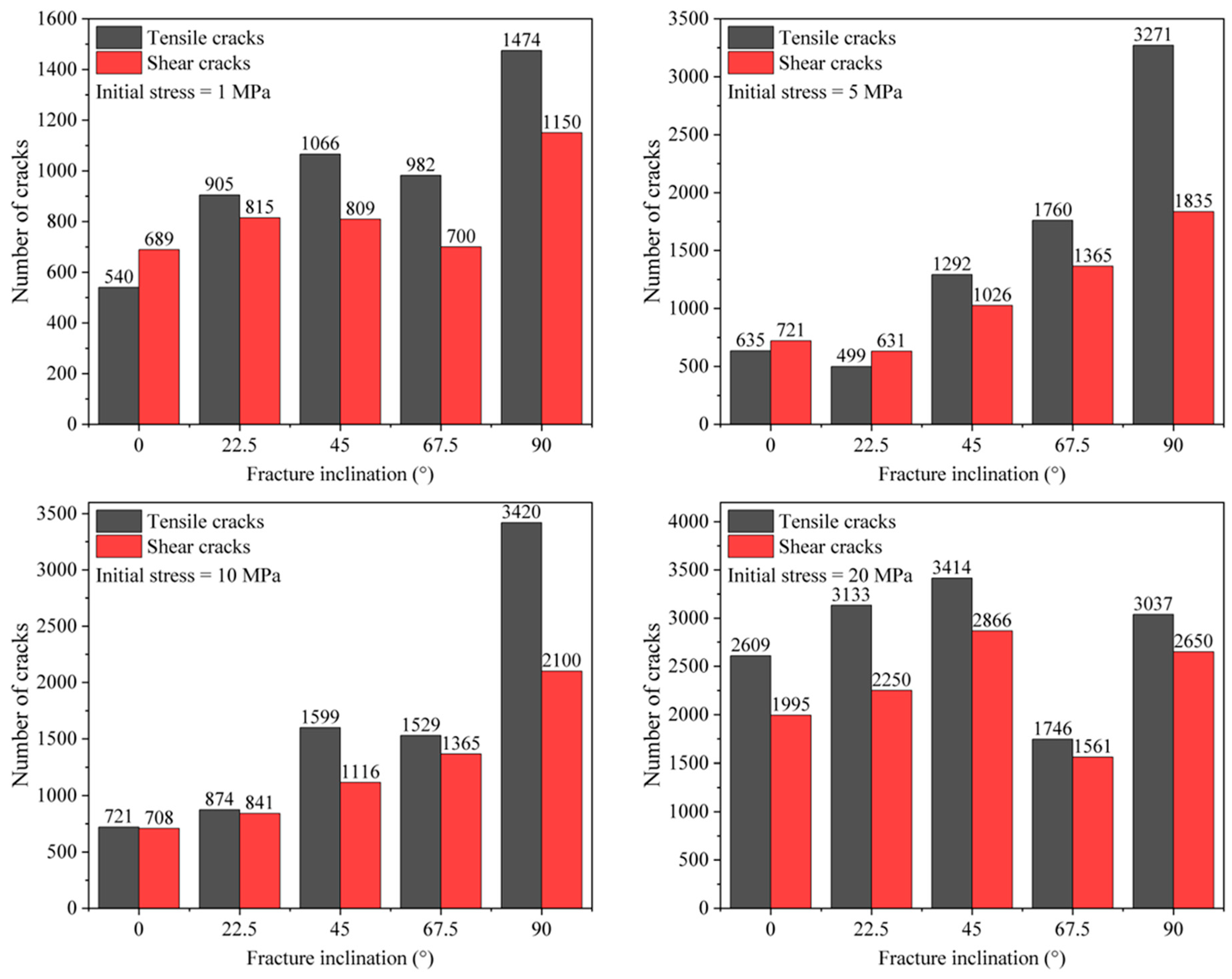
Figure 7 plots the evolution of tensile and shear crack counts during failure. The results indicate that both the number and type of cracks significantly influence the composite’s failure mode, and that the pre-existing fracture orientation and initial confining stress strongly affect crack distribution and prevalence.
When the initial confining stress is below 10 MPa, both tensile and shear crack counts increase with rising fracture dip angle. At 20 MPa, however, the influence of dip angle on crack counts becomes relatively minor. As the initial stress increases from 1 MPa to 20 MPa, the number of tensile cracks in the composite steadily rises, particularly under high-stress conditions, indicating that higher confining stress promotes tensile cracking. Shear crack counts vary less dramatically with stress but still increase noticeably at higher stresses, revealing an enhanced tendency toward shear failure under elevated confinement. These findings demonstrate that initial confining stress exerts a complex control on crack evolution. Under high confinement, the composite develops more extensive microcrack networks, and the interaction between tensile and shear cracks becomes the key determinant of failure.
Under high stress, the composite’s failure mode is characterized by a more intricate crack network featuring numerous tensile and shear cracks. This insight is crucial for designing concrete–fractured rock composites, especially in high-stress zones where structural safety and durability depend on accurately anticipating crack interaction and propagation.
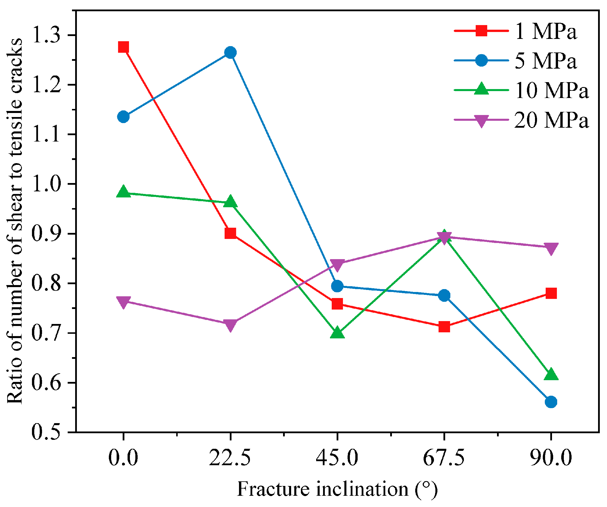
A numerical table summarizing the ratio of shear to tensile cracks under varying fracture inclinations and confining pressures is provided (
Table 4), complementing
Figure 8. In
Figure 8 and
Table 4, at 1 MPa, shear cracks outnumber tensile cracks by more than 1.2:1 when the interface is nearly parallel to the loading direction, indicating shear-dominated slip. At 20 MPa, however, the shear-to-tensile crack ratio falls below 1 across all dip angles, demonstrating that high lateral stress favors crack opening and tensile failure. Moreover, under low confinement (<10 MPa), the shear-to-tensile crack ratio decreases with increasing dip angle, marking a transition from shear-dominated to tension-dominated mechanisms. At 20 MPa, this ratio remains relatively constant, reflecting the high stress’s overriding influence on crack mode. Previous experiments showed that, under high-stress conditions, macroscopic failure was predominantly shear [
40], which is somewhat at odds with the numerical predictions. Previous authors have suggested that such macroscopic shear failure can actually arise from arrays of microscopic tensile cracks [
41].
In summary, confining stress and fracture geometry jointly govern the composite’s failure mode. High lateral confinement suppresses micro-shear damage while promoting micro-tensile failure. Additionally, steep fracture dips favor tensile crack formation whereas shallow dips encourage shear failure. High confinement can modify these trends, emphasizing the need to consider both dip angle and stress conditions when designing and assessing concrete–fractured rock composite structures in complex geological settings.
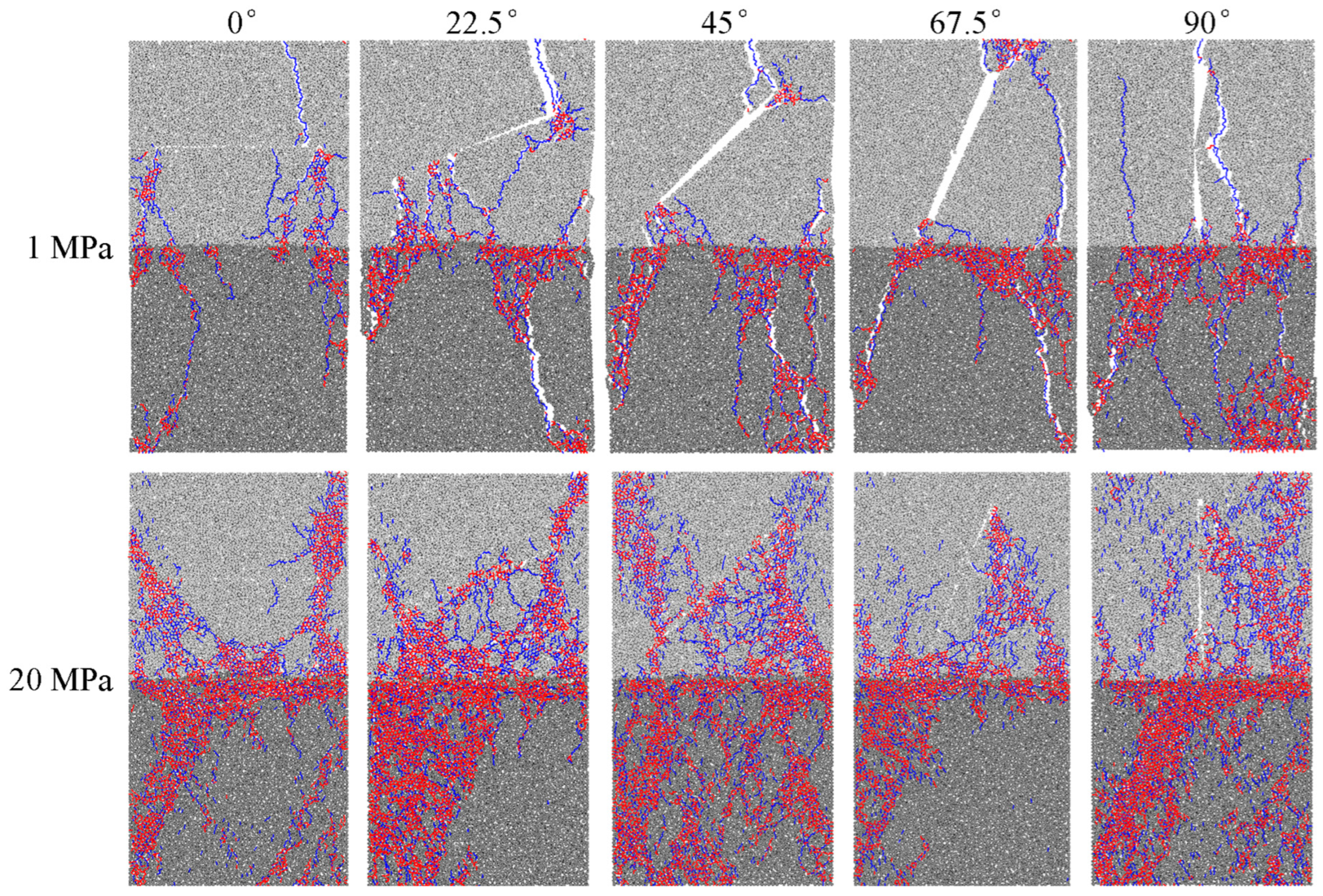
Figure 9 visualizes the internal crack patterns under combined pre-existing fracture and confining-stress effects. Under low confinement (1 MPa), a dominant main fracture (white) emanates from above the pre-existing fracture tip, with secondary shear cracks propagating along the concrete–rock interface. Low-dip samples more readily develop through-going macro-cracks in the rock layer, explaining the strength trends noted in
Section 3.2. Under high confinement (20 MPa), the crack network becomes denser and more dispersed: numerous fine tensile microcracks (red) open above the interface, while shear cracks (blue) persist but are widened and elongated by tensile damage. Here, shear cracks are interwoven with tensile cracks throughout the failure zone, indicating that high stress not only increases overall crack density, but also fosters a complex, multi-scale, mixed fracture network.
Overall,
Figure 9 vividly demonstrates the coupled control of pre-existing fracture geometry and confining stress on crack distribution and failure morphology. Specifically, at low fracture angles (<22.5°), low confinement leads to microscale shear sliding dominating, whereas high confinement leads to microscale tensile failure dominating. As the fracture angle increases (>45°), microscale tensile failure remains dominant regardless of the magnitude of the confining pressure. These mechanisms underscore the importance of accounting for both fracture orientation and in situ stress in designing and evaluating the stability of CFRCs.
4. Insights and Prospects
This study employs the DEM to systematically elucidate, for the first time, the coupled mechanical response mechanisms of concrete–fractured rock composites under varying confinement pressures and fracture inclinations. We develop a heterogeneous concrete–rock composite model that integrates the PBM for cementation failure with the SJM for interface frictional slip. By quantifying the combined effects of fracture inclination (0–90°) and confinement pressure (1–20 MPa) on composite strength and crack propagation paths, we find that high confinement induces a transition to a microscale tensile-dominated failure mode, which is in sharp contrast to the microscale shear-controlled mechanisms observed under low confinement. These findings transcend the limitations of conventional macroscopic analyses and introduce a new paradigm for high-fidelity modeling and failure prediction of concrete–fractured rock structures.
The practical implications for large-scale infrastructure are direct and significant. First, the pronounced influence of fracture inclination on peak strength and failure mode suggests that excavation and support strategies must be tailored to the subsurface fracture geometry to mitigate unfavorable failure tendencies. Second, the strengthening effect of high confinement pressure, which promotes tension-driven failure, indicates that strategic application or conservation of lateral stresses can markedly enhance load-bearing capacity and stability in high-stress environments. Finally, the detailed micromechanical insights into crack evolution highlight the necessity of dual control strategies in design, simultaneously addressing interface slip and crack opening.
For instance, in high-stress tunnel construction through low-inclination fractured rock, strengthening measures such as compressible linings to maintain confinement can suppress tensile crack network development. Shallow urban metro sections may benefit from steel fiber–reinforced concrete to bolster shear resistance, distributed fiber-optic sensing to monitor crack progression, and alert thresholds that activate when tensile cracks exceed a certain length. For slope stabilization, grouting and reinforcement spacing should be adjusted according to fracture inclination, with denser reinforcement applied for inclinations between 0 and 30°. Overall, this work provides the theoretical basis for precision design, performance forecasting, and health monitoring of fractured composite structures, particularly in complex geological settings, such as tunnel linings, underground caverns, and high cut slopes.
The present quasi-static, rate-independent model may underestimate damage under dynamic loading scenarios. However, incorporating viscoplasticity into the PBM–SJM framework, with strain-rate dependent bond strengths and dashpot elements, would enable the model to capture dynamic effects, such as blast or impact loading in future studies.
To extend the present framework toward 3D multi-scale analysis, from nanoscale cement–aggregate interfaces to meter-scale structures, the contact logic would need refinement to explicitly model heterogeneous particle interactions at micro- and mesoscale. At the same time, parallel computing strategies such as domain decomposition and GPU acceleration would be required to efficiently handle the substantially increased particle count and ensure numerical stability. To advance smart infrastructure maintenance, we recommend incorporating AI-based crack recognition techniques. Existing technologies, such as convolutional neural networks (CNNs) for image-based crack detection and YOLO (You Only Look Once) for real-time object detection, can be adapted to identify and classify cracks in concrete–rock composites. These algorithms, integrated with sensor or image-based data from field monitoring systems, can be used to detect crack types, monitor crack progression, and predict failure risks in real-time. By combining these AI technologies with 3D DEM models, we can develop a robust framework for intelligent monitoring and predictive maintenance.
5. Conclusions
This study employs the DEM to systematically investigate the coupled effects of confining pressure and fracture inclination on the mechanical behavior of concrete–fractured rock composites. The findings provide a theoretical basis for the refined design and safety assessment of fractured rock–concrete structures. The key conclusions are as follows:
Increasing confining pressure from 1 to 20 MPa significantly raises the load-bearing capacity of the composite. High confining pressure strengthens the collaborative load-bearing capacity of rock and concrete by both suppressing crack opening and increasing frictional resistance at discontinuities.
As the fracture inclination increases from 0° to 90°, the composite’s peak strength increases overall.
Under low confinement (<10 MPa), the shear-to-tensile crack ratio decreases with increasing dip angle, marking a transition from shear-dominated to tension-dominated mechanisms. At 20 MPa, the ratio remains relatively constant, with tensile failure being dominant. This transition reveals how confining pressure physically controls failure paths by altering crack propagation thresholds.
In deep-buried tunnels and high-stress zones, one should leverage confining pressure strengthening by optimizing support stiffness. In shallow-buried urban transit tunnels, shear resistance at concrete–rock interfaces should be enhanced to suppress low-pressure shear sliding. Fractured rock reinforcement should prioritize treatment of weak planes with inclinations below 30°.
Future work should extend to 3D DEM simulations based on computed tomography (CT), integrate field monitoring data to validate micromechanical crack evolution, and develop AI-based, real-time, crack-type recognition algorithms to advance smart infrastructure maintenance.
Author Contributions
Conceptualization, Z.Y.; Methodology, K.C.; Software, Z.Y.; Validation, K.C.; Investigation, K.C.; Writing—original draft, K.C.; Writing—review & editing, Z.Y.; Supervision, Z.Y. All authors have read and agreed to the published version of the manuscript.
Funding
This work was supported by the Scientific and Technological Research Project of Henan Province (Grant No. 252102321098); and the Key Scientific Research Project of Colleges and Universities of Henan Province (24A620003).
Data Availability Statement
Data will be made available upon request.
Acknowledgments
The authors sincerely thank the editors and the reviewers for their efforts in improving this paper.
Conflicts of Interest
The authors declare that they have no known competing financial interests or personal relationships that could have appeared to influence the work reported in this paper.
References
- Chen, J.; Zhou, L.; Zhu, Z.; Shui, X.; Ma, L.; Wang, M. Interface Stress Analysis and Failure Mechanism of Rock–Concrete Composite Structures Under Multi-directional Stress Waves. Rock Mech. Rock Eng. 2024, 57, 9651–9668. [Google Scholar] [CrossRef]
- Wang, X.; Mu, W.; Li, L.; Yang, T.; Du, S.; Bai, M. Shear Failure Mechanism of Fiber-Reinforced Concrete–Rock Interface Under Freeze–Thaw Conditions. Rock Mech. Rock Eng. 2025, 58, 8819–8844. [Google Scholar] [CrossRef]
- Liu, S.; Zhao, J.; Cheng, F.; Yu, H.; Chen, J. Mechanical Behavior and Failure Mechanism of Rock–Concrete Composites Under the Coupling Effect of Inclined Interface Angle and Ground Temperature. Symmetry 2025, 17, 52. [Google Scholar] [CrossRef]
- Deng, X.; Shen, M.; Zhao, Y.; Bi, J.; Wang, C.; Zhang, Y.; Li, Y.; Ning, L. Effect of interface roughness on mode I-II fracture behavior of concrete-sandstone. Theor. Appl. Fract. Mech. 2025, 138, 104943. [Google Scholar] [CrossRef]
- Cascardi, A.; Verre, S.; Ombres, L.; Aiello, M.A. Carbon Fabric Reinforced Cementitious Mortar confinement of concrete cylinders: The matrix effect for multi-ply wrapping. Compos. Struct. 2024, 332, 117919. [Google Scholar] [CrossRef]
- Yang, S.-Q.; Huang, Y.-H.; Ranjith, P.G.; Jiao, Y.-Y.; Ji, J. Discrete element modeling on the crack evolution behavior of brittle sandstone containing three fissures under uniaxial compression. Acta Mech. Sin. 2015, 31, 871–889. [Google Scholar] [CrossRef]
- Shen, Y.; Wang, Y.; Yang, Y.; Sun, Q.; Luo, T.; Zhang, H. Influence of surface roughness and hydrophilicity on bonding strength of concrete-rock interface. Constr. Build. Mater. 2019, 213, 156–166. [Google Scholar] [CrossRef]
- Guo, T.; Wang, H.; Si, X.; Pu, C.; Liu, Z.; Zhang, Q.; Liu, W. Fracture Characteristics and Tensile Strength Prediction of Rock–Concrete Composite Discs Under Radial Compression. Mathematics 2024, 12, 3510. [Google Scholar] [CrossRef]
- Bi, J.; Shen, M.; Zhao, Y.; Wang, C.; Deng, X.; Zhang, K. Study on the damage characteristics of concrete-rock composite after exposure to high-temperature environments using nuclear magnetic resonance. Bull. Eng. Geol. Environ. 2023, 82, 380. [Google Scholar] [CrossRef]
- Zhao, B.; Liu, Y.; Huang, T.; Wang, X. Experimental Study on Strength and Deformation Characteristics of Rock–Concrete Composite Specimens Under Compressive Condition. Geotech. Geol. Eng. 2019, 37, 2693–2706. [Google Scholar] [CrossRef]
- Chen, H.; Jiang, Y.; Pan, R.; Wang, B.; Zhang, S.; Zhang, J.; Ma, X. Temperature-dependent shear behavior and constitutive model of the rock–concrete interface. Deep. Undergound Sci. Eng. 2025. [Google Scholar] [CrossRef]
- Wu, J.; Sun, W.; Yang, S.; Wu, Q.; Zhang, J.; Chen, X. Analysis of Initial Crack Propagation and Fracture Behavior at Concrete–Rock Bimaterial Interface. Arab. J. Sci. Eng. 2024. [Google Scholar] [CrossRef]
- Zhang, T.; Wang, H.; Chen, M.; Niu, L.; Zhu, W. Effect of interfacial characteristics on dynamic splitting behavior of quasi rock-concrete composite layer: Towards resilient tunnel support against rock burst. Tunn. Undergr. Space Technol. 2025, 155, 106134. [Google Scholar] [CrossRef]
- Gou, D.; Li, Y.; Hu, Y.; Zhou, Z.; Zhang, S.; Li, K.; Wang, K. Investigations on mechanical behaviors and failure mechanisms of rock-concrete composite specimens with different interface inclinations subjected to freeze-thaw cycles and uniaxial compression. Eng. Fract. Mech. 2025, 322, 111196. [Google Scholar] [CrossRef]
- Potyondy, D.O.; Cundall, P.A. A bonded-particle model for rock. Int. J. Rock Mech. Min. Sci. 2004, 41, 1329–1364. [Google Scholar] [CrossRef]
- Asadi, M.S.; Rasouli, V.; Barla, G. A Bonded Particle Model Simulation of Shear Strength and Asperity Degradation for Rough Rock Fractures. Rock Mech. Rock Eng. 2012, 45, 649–675. [Google Scholar] [CrossRef]
- Hofmann, H.; Babadagli, T.; Zimmermann, G. A grain based modeling study of fracture branching during compression tests in granites. Int. J. Rock Mech. Min. Sci. 2015, 77, 152–162. [Google Scholar] [CrossRef]
- Zhang, X.-P.; Wong, L.N.Y. Cracking Processes in Rock-Like Material Containing a Single Flaw Under Uniaxial Compression: A Numerical Study Based on Parallel Bonded-Particle Model Approach. Rock Mech. Rock Eng. 2012, 45, 711–737. [Google Scholar] [CrossRef]
- Xu, Y.; Geng, F.; Luan, H.; Chen, J.; Yang, H.; Gao, P. Three-Dimensional Mesoscopic DEM Modeling and Compressive Behavior of Macroporous Recycled Concrete. Buildings 2025, 15, 2655. [Google Scholar] [CrossRef]
- Li, X.; Liang, Y.; Qian, Y. 3D DEM framework for simulating the influence of aggregate strength on the dynamic splitting tensile fracture behavior of concrete. Comput. Part. Mech. 2025. [Google Scholar] [CrossRef]
- Wang, P.; Gao, N.; Ji, K.; Stewart, L.; Arson, C. DEM analysis on the role of aggregates on concrete strength. Comput. Geotech. 2020, 119, 103290. [Google Scholar] [CrossRef]
- Peng, Z.; Liu, Q.-f.; Gao, X.; Zhao, X.-Y.; Xia, J.; Xiong, Q.-x. Effects of aggregate distribution on the cracking behavior of concrete: A discrete element method study. Cem. Concr. Compos. 2025, 162, 106119. [Google Scholar] [CrossRef]
- Yang, Z.; Tao, M.; Fei, W.; Yin, T.; Gu, X.; Narsilio, G.A. A coupled thermo-mechanical model for investigating cracking and failure of composite interbedded rock. Eng. Geol. 2024, 339, 107645. [Google Scholar] [CrossRef]
- Zhao, Y.; Zhao, G.; Zhou, J.; Ma, J.; Cai, X. Failure mechanism analysis of rock in particle discrete element method simulation based on moment tensors. Comput. Geotech. 2021, 136, 104215. [Google Scholar] [CrossRef]
- Yang, Z.; Tao, M.; Ranjith, P.G. Novel insights into grain size effect of stressed crystalline rock using weakened grain boundary model. Int. J. Rock Mech. Min. Sci. 2025, 189, 106098. [Google Scholar] [CrossRef]
- Yang, Z.; Tao, M.; Yin, T.; Memon, M.B.; Ranjith, P.G. Grain-Based Modeling for Heterogeneous Rock Fragmentation Under Stressed Conditions and TBM Cutter Spacing Optimization. Rock Mech. Rock Eng. 2024, 57, 10467–10489. [Google Scholar] [CrossRef]
- Yang, Z.; Alqawasmeh, Q.I.; Ma, J.; Dashtgoli, D.S.; Cong, Z.; Li, Y. Critical grain size and shear behavior of polycrystalline rocks under confining pressure: A moment tensor-based GBM approach. Comput. Geotech. 2025, 186, 107431. [Google Scholar] [CrossRef]
- Gong, Q.M.; Zhao, J. Influence of rock brittleness on TBM penetration rate in Singapore granite. Tunn. Undergr. Space Technol. 2007, 22, 317–324. [Google Scholar] [CrossRef]
- Zhang, X.-P.; Ji, P.-Q.; Liu, Q.-s.; Liu, Q.; Zhang, Q.; Peng, Z.-H. Physical and numerical studies of rock fragmentation subject to wedge cutter indentation in the mixed ground. Tunn. Undergr. Space Technol. 2018, 71, 354–365. [Google Scholar] [CrossRef]
- Yin, T.-B.; Zhuang, D.-D.; Li, M.-J.; Li, X.-B. Numerical simulation study on the thermal stress evolution and thermal cracking law of granite under heat conduction. Comput. Geotech. 2022, 148, 104813. [Google Scholar] [CrossRef]
- Zhu, X.; Guo, Y.; Bu, J.; Chen, X. Experimental and Numerical Study on Triaxial Failure Mechanism of Rock–Concrete Combined Body. Rock Mech. Rock Eng. 2025, 58, 3461–3477. [Google Scholar] [CrossRef]
- Mehranpour, M.H.; Kulatilake, P.H.S.W. Improvements for the smooth joint contact model of the particle flow code and its applications. Comput. Geotech. 2017, 87, 163–177. [Google Scholar] [CrossRef]
- Peng, J.; Wong, L.N.Y.; Teh, C.I.; Li, Z. Modeling Micro-cracking Behavior of Bukit Timah Granite Using Grain-Based Model. Rock Mech. Rock Eng. 2018, 51, 135–154. [Google Scholar] [CrossRef]
- Mas Ivars, D.; Pierce, M.E.; Darcel, C.; Reyes-Montes, J.; Potyondy, D.O.; Paul Young, R.; Cundall, P.A. The synthetic rock mass approach for jointed rock mass modelling. Int. J. Rock Mech. Min. Sci. 2011, 48, 219–244. [Google Scholar] [CrossRef]
- Yang, Z.; Tao, M.; Yin, T.; Luo, H.; Chen, C.; Ranjith, P.G. Fragmentation characteristics of stressed rock with weak interlayers using double TBM cutters. Eng. Fract. Mech. 2025, 315, 110845. [Google Scholar] [CrossRef]
- Guo, P.; Zhang, P.; Bu, M.; Wang, J.; Zheng, X.; He, M. Microcracking behavior and damage mechanism of granite subjected to high temperature based on CT-GBM numerical simulation. Comput. Geotech. 2023, 159, 105385. [Google Scholar] [CrossRef]
- Zhang, X.-P.; Liu, Q.; Wu, S.; Tang, X. Crack coalescence between two non-parallel flaws in rock-like material under uniaxial compression. Eng. Geol. 2015, 199, 74–90. [Google Scholar] [CrossRef]
- Zhang, X.-P.; Wong, L.N.Y. Crack Initiation, Propagation and Coalescence in Rock-Like Material Containing Two Flaws: A Numerical Study Based on Bonded-Particle Model Approach. Rock Mech. Rock Eng. 2013, 46, 1001–1021. [Google Scholar] [CrossRef]
- Li, X.F.; Zhang, Q.B.; Li, H.B.; Zhao, J. Grain-Based Discrete Element Method (GB-DEM) Modelling of Multi-scale Fracturing in Rocks Under Dynamic Loading. Rock Mech. Rock Eng. 2018, 51, 3785–3817. [Google Scholar] [CrossRef]
- Du, K.; Yang, C.; Su, R.; Tao, M.; Wang, S. Failure properties of cubic granite, marble, and sandstone specimens under true triaxial stress. Int. J. Rock Mech. Min. Sci. 2020, 130, 104309. [Google Scholar] [CrossRef]
- Bewick, R.P.; Kaiser, P.K.; Bawden, W.F.; Bahrani, N. DEM Simulation of Direct Shear: 1. Rupture Under Constant Normal Stress Boundary Conditions. Rock Mech. Rock Eng. 2014, 47, 1647–1671. [Google Scholar] [CrossRef]
| Disclaimer/Publisher’s Note: The statements, opinions and data contained in all publications are solely those of the individual author(s) and contributor(s) and not of MDPI and/or the editor(s). MDPI and/or the editor(s) disclaim responsibility for any injury to people or property resulting from any ideas, methods, instructions or products referred to in the content. |
© 2025 by the authors. Licensee MDPI, Basel, Switzerland. This article is an open access article distributed under the terms and conditions of the Creative Commons Attribution (CC BY) license (https://creativecommons.org/licenses/by/4.0/).

