Abstract
This paper presents a novel integration of bioclimatic-passive architectural elements—Trombe walls, pergolas, and deciduous climbers—in the context of residential buildings in Eastern and Central Europe, a combination that remains largely underexplored in the current literature. The innovativeness of the proposed concept is reflected in the combined use of the following building elements: three types of passive Trombe wall (single-glazed, double-glazed, and triple-glazed), pergolas, and four types of deciduous climbers (V. coignetiae, H. lupulus, W. sinensis, and A. macrophylla). By using meteorological data for the towns Kragujevac and Kielce, the influence of location parameters for two dominant European climate zones (moderate continental and continental) is also included in this investigation. The initial single-family building models were created following the Serbian and Polish rulebooks on energy efficiency for new buildings and equipped with the same thermo-technical systems and people occupancy conditions. Based on the conducted simulations (using Google SketchUp 8 and EnergyPlus 7.1) and obtained results on the annual level, the following main conclusions can be drawn: (1) a moderate continental climate is more suitable for implementing the proposed concept; (2) a single-glazed passive Trombe wall is not energy or environmentally justified; (3) the energy, environmental, and economic benefits for both selected locations are greatest in the case of the combined use of pergolas, V. coignetiae, and triple-glazed passive Trombe wall; and (4) before the wider commercial application of the proposed concept in the future, efforts should be made to explore economic opportunities, which, among other things, involve a focus on market stability and accessibility.
1. Introduction
To bring the residential building sector (RBS) closer to the basic (primary) concept of sustainable development [1], the European scientific community intensively promotes auxiliary (secondary) concepts where buildings are treated as structures that need to meet the following criteria: (1) provide optimal (air, thermal, lighting, and sound) and comfortable conditions [2] for human occupancy, health, work, and functionality; (2) minimize final and primary energy consumption [3]; (3) reduce dependence on conventional energy sources [4]; (4) decrease greenhouse gas emissions [5]; (5) preserve the environment [6]; and (6) mitigate climate change [7].
All RBS concepts (basic and auxiliaries) represent a combination of multidisciplinary measures and strategies that include: (1) location choice; (2) building form factor; (3) thermal envelope structure and design; (4) internal project temperature; and (5) smart thermo-technical systems (space heating, space cooling, ventilation, air conditioning, heat recovery, lighting, electric equipment, water heating, etc.), renewable energy sources (RESs), and mandatory responsible occupant behavior.
Experimental, numerical, and theoretical studies and investigations in the available literature indicate that passive RES measures and strategies, primarily those using solar and geothermal energy, are gaining increasing importance, including building orientation [8], room layout, sustainable materials [9], window–wall ratio, different soil layers [10], Trombe wall (TW), deciduous climbers, selective facade walls, phase change materials (PCMs), overhangs [11], blinds, pergolas, awnings, curtains, etc. They can significantly reduce final and primary energy consumption for space heating and cooling, and lower financial costs and greenhouse gas emissions.
An interesting massive construction element that is always oriented toward the equator [12], known as TW [13] and solar wall [14], is intended to indirectly accumulate solar energy [15] and transmit it to heated spaces (heating rooms or thermal zones, i.e., TZs) by convection and radiation [16]. In [17], the two basic types of TWs can be found: (1) active Trombe wall (ATW) and (2) passive Trombe wall (PTW). The first type, i.e., ATW, has dampers of various shapes, sizes, and purposes. Also, their number can vary from case to case. Depending on the purpose, dampers can be placed toward TZs [18] and the outside [19] to ensure air circulation. Air circulation provides better forced [20] or natural [21] convective heating (during the winter season) and cooling (during the summer season) of the TZs [22]. The second type, i.e., PTW, has neither external nor internal dampers [23], which means that the air mass is trapped between the glazed surface and the selectively coated massive wall. This variant is simpler and cheaper, but also less favorable due to the elimination of air circulation and convective heating.
Pergolas are shading building elements [24] because they are primarily intended for sun protection. Pergolas can be used for protection from rain and other weather conditions. Their aesthetic aspect is also important. The following table (Table 1) shows the different criteria for classifying pergolas used in practice.

Table 1.
Different classification criteria and types of pergolas.
Climbers [25] are plants used to decorate yards, pergolas, terraces, balconies, external walls (green facades [26]), etc. In some special circumstances, they are also used in internal spaces. The primary feature of climbers is their rapid growth, enabling them to achieve the desired spatial form in a relatively short period. Besides their decorative role (such as beautifying spaces, enhancing aesthetics, and providing privacy), they have significant energy potential that becomes evident during the summer [27]. Particularly interesting are deciduous climbers [28], which offer energy and environmental benefits throughout the year. The dense foliage and flowers create natural shade (bio-shading effects [29]) in the summer, reducing cooling energy needs.
1.1. Literature Review
Investigations of the passive solar systems, such as TW, in Serbia are primarily based on the application of mathematical and numerical methods. The following table (Table 2) presents their scientific contributions in chronological order. The situation in the Polish literature is somewhat better, due to the larger number of experimental papers (Table 3).
Table 2.
Literature examples of the Trombe wall implemented in Serbian residential buildings.
Table 3.
Literature examples of the Trombe wall implemented in Polish residential buildings.
Pergolas are an under-researched strategy in Serbian and Polish RBSs. Currently, there are few studies in the Polish literature on this topic, which are mainly analyzed from an architectural perspective: the Museum of King John III’s Palace at Wilanów [46], a neo-Gothic chapel located in the Stradom district of Czestochowa [47], and the implementation of environmental architectural projects in the areas of historic urban spaces [48].
However, an experiment in the Transylvania region showed that properly dimensioned fixed pergolas can block up to 90% of incident summer solar radiation, while still allowing winter sunlight to pass through [49]. For instance, Indian buildings (with an emphasis on energy, environmental, and economic benefits that can be achieved by installing pergolas and various roof strategies) were the research subject in [50]. In [51], the specific engineering solution is presented that combines active (photovoltaic panels) and passive (pergolas) solar systems. The presented concept maximizes solar shading effects, natural ventilation, and electricity production, while ensuring sufficient daylight and without violating privacy. Verheijen et al. [52] utilized the roof pergolas to reduce thermal stress and improve temperature and visual comfort conditions. They opted for a simple and free-standing variant. Thermal and structural analyses have confirmed that, among passive solar systems, such building elements have great commercial potential.
The situation is somewhat better when it comes to the implementation of deciduous climbers in Serbian and Polish RBSs to achieve energy and environmental goals.
Dimitrijević-Jovanović et al. [53] presented a paper that investigates the correlations between the next adopted “nodes”: (1) building thermal envelope, (2) green (climatic) systems, and (3) the environment. Energy flows characteristic of public buildings located in the Balkan Peninsula (Serbia and Croatia), equipped with nature-based solutions, were investigated by Savić et al. in [54]. Jovanović et al. [55] considered various passive design strategies, including ventilated green facades, to increase building status (in energy efficiency terms). The main goal presented in [56] is the integration of buildings with green and sustainable energy efficiency practices.
On the other hand, a conceptual framework for the design of vertical green (and bioclimatic) facades was presented by Seyrek Şık et al. in [57]. Costa and James [58] concluded that vegetation offers the opportunity to create, at low cost, building service installations that make negligible noxious discharges to its surroundings. Mitigation of the overheating effects using greenery in Polish climate conditions was numerically investigated in [59]. A significant scientific contribution to the development of solar shading elements (pergolas, pavilions, tents, cables, and plants) as PSSs was made by Petschek and Gas in [60]. Finally, a mathematical model of the climbing vegetation was created in [61]. After laboratory validation, the model was tested in different European climate zones (monitoring energy and environmental parameters). The results showed that climbing foliage on facades does not behave in the same way in selected climate zones, which can significantly reduce techno-economic efficiency.
1.2. State-of-the-Art
Based on a review of the available literature, it was observed that Eastern and Southeastern Europe underutilize available climatic (meteorological) resources for energy purposes. The promotion and implementation of passive solar measures and strategies to achieve energy efficiency in buildings have not reached their full potential. In other words, these regions lag behind the leading global trends in this area.
To change this situation in the coming period, this paper focuses on a novel concept that combines different passive solar measures and strategies in the building sector. Namely, it has been noted that the bioclimatic-passive architecture concept, which combines passive Trombe walls, pergolas, and deciduous climbers, has not yet been investigated. This is precisely the scientific gap that this paper fills.
Since the passive Trombe wall is a type of heating building element, and pergolas and deciduous climbers are types of cooling building elements, a starting hypothesis is based on the claim that final and primary energy consumption, CO2 emissions, and economic costs can be reduced on an annual level.
The energy, environmental, and economic aspects of the proposed building concept are intended for moderate continental and continental climate zones. Consequently, the study includes two locations (towns): Kragujevac (in the Serbian climate zone) and Kielce (in the Polish climate zone).
Complete numerical research was conducted following the current Serbian and Polish rulebooks on energy efficiency for new buildings. To ensure comparability of the results, both single-family buildings are equipped with the same thermo-technical systems and people occupancy.
Among other things, this paper aims to demonstrate that rather simple strategies, such as energy efficiency measures, can enhance the quality of life in the residential sector in terms of comfort, costs, and environmental attitude.
2. Materials and Methods
2.1. Building Model
The analyzed residential building (Figure 1) is intended to accommodate a family of four during the year. The total floor area and total volume of the single-family building are Afl,tot = 114.45 m2 and Vtot = 297.57 m3. The form factor is ftot = Atot/Vtot = 302.06 m2/297.57 m3 = 1.02 1/m and the window–wall ratio is WW = 8.74%. The external door is located on the west side.
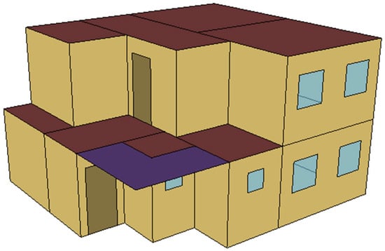
Figure 1.
Isometric view of the analyzed building.
The arrangement of rooms is illustrated in Figure 2. On the first floor (ground floor, Figure 2a), there are the hall (H1), staircase (S), toilet (T), study room (SR), kitchen (K), and living room with dining room (LR). The second floor (Figure 2b) contains the bedrooms (BR1 and BR2), another hall (H2), and a bathroom (BT).
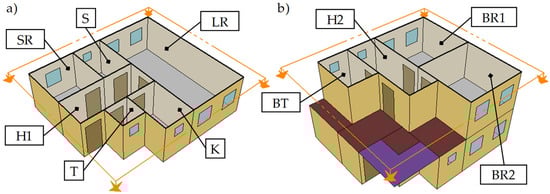
Figure 2.
Horizontal cross-section view of the analyzed building and room layouts: (a) first floor and (b) second floor. Legend: BR1—bedroom 1, BR2—bedroom 2, BT—bathroom, H1—hall 1, H2—hall 2, K—kitchen, LR—living room, S—staircase, SR—study room, and T—toilet.
The heat transfer coefficients U [W/m2K] of the thermal envelope (Figure 3) were adopted following the principles of the Serbian [62] (index SRB) and Polish [63] (index POL) rulebooks on energy efficiency for new buildings.
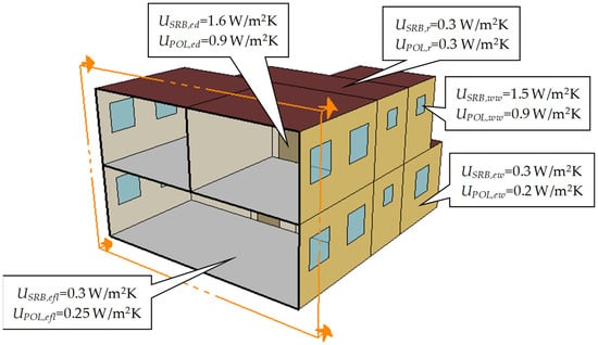
Figure 3.
Vertical cross-section view of the analyzed building and thermal characteristics of the thermal envelope following the Serbian and Polish rulebooks. Legend: Ued [W/m2K]—heat transfer coefficient for the external door, Uefl [W/m2K]—heat transfer coefficient for the external floor, Uew [W/m2K]—heat transfer coefficient for the external wall, Ufr [W/m2K]—heat transfer coefficient for the flat roof, and Uww [W/m2K]—heat transfer coefficient for the window.
U-values for the ground floor are the same in both cases, while the rest energy efficiency criteria are much stricter (almost 1.8 times for the external door) in the Polish rulebook compared to the Serbian rulebook (Figure 3).
2.2. People Occupancy and Thermo-Technical Systems
Simulation settings for people and thermo-technical systems are the same for both locations in the present study: Kragujevac and Kielce.
By the recommendations available in [62,63,64,65,66], internal heat gains were determined based on the next simulation settings: specific daily people occupancy in the analyzed building is ppl = 60 m2/per, specific metabolic activities level of the people in the analyzed building is qpl = 72.07 W/per, specific annual electricity consumption from electric equipment and lighting in the analyzed building is eeel = 20 kWh/m2, and specific annual electricity consumption from water heater in the analyzed building is ewh = 10 kWh/m2. It was also adopted (from the same sources) that the daily presence of people in the analyzed building is τpl = 12 h (00:00–08:00 h, 17:00–18:00 h, and 21:00–24:00 h) and the specific number of fresh air changes is nair = 0.7 m3/h/m2. The analyzed building is also equipped with space heating and cooling systems (Figure 4) to maintain thermal comfort in all rooms (Figure 2) within strictly defined limits during the year: heating control temperature is theat = 20 °C and cooling control temperature is tcool = 26 °C. The heating system does not allow the temperature to fall below theat = 20 °C, while the cooling system does not allow the temperature to be higher than tcool = 26 °C. The heating system is very simple because it is based on the use of individual electric heaters. The power of each electric heater is Qrad = 3500 W, while the thermal efficiency is ηrad = 0.98. For cooling purposes, classic individual air-conditioned units are used, where cooling power is Qacu = 3500 W and the coefficient of performance is COPacu = 2.61.
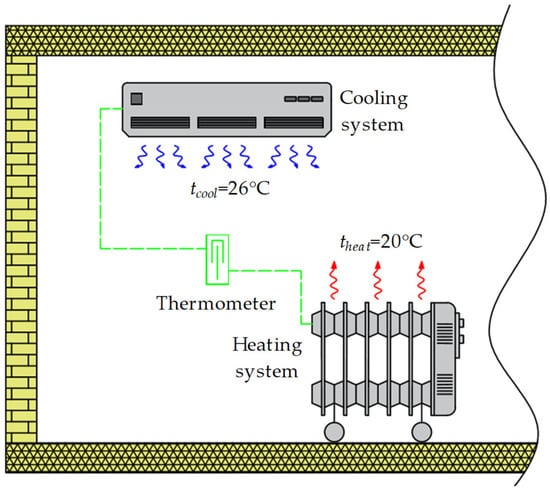
Figure 4.
Adopted space heating and cooling systems.
Figure 5 shows the vertical cross-section view (Figure 5a) and isometric view (Figure 5b) of the adopted PTW (example for triple-glazing) in the analyzed building. The geometric and thermal characteristics of all layers in the PTW construction are shown in Table 4.
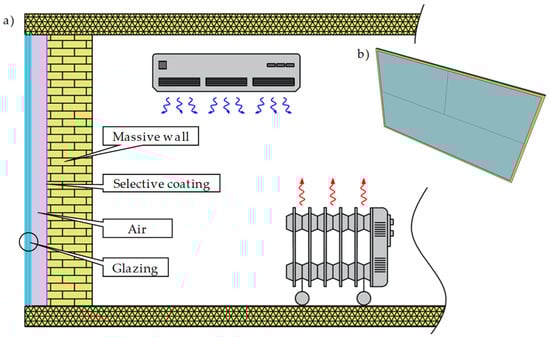
Figure 5.
Triple-glazed passive Trombe wall: (a) vertical cross-section view and (b) isometric view.
Table 4.
The geometric-thermal performance of the triple-glazed passive Trombe wall [67].
Figure 6 shows the adopted pergolas concept. In this case, the pergolas are made of wooden planks with a square cross-section measuring 40 × 40 mm.
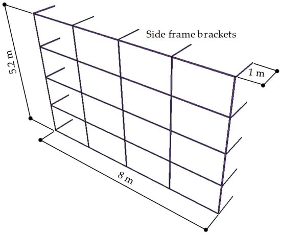
Figure 6.
Isometric view of the wooden pergolas.
In this case, reducing the final energy consumption for space cooling is a secondary issue and not a priority. The specific shape of the vertically placed supporting frame (Figure 6), in front of the PTW (Figure 5), indicates that the primary purpose of the pergolas is to provide support for the vegetative development of deciduous climbers. Through the side frame holders (13 of them), the pergolas are attached to the PTW and placed at a distance of 1 m from it (Figure 6). This provides enough space for the unhindered growth of plants and their maintenance (on the one hand), and also prevents possible mechanical, optical, and thermal damage to the PTW (on the other hand). The external dimensions of the frame correspond to the external dimensions of the southern facade (8 × 5.2 m), and the total length of the wooden planks is 79 m.
Bioclimatic solar shading during the summer season is provided by deciduous climbers (Figure 7). In this paper, opportunities and barriers to applying the following four types of plants are numerically investigated and analyzed (Table 5): V. coignetiae, H. lupulus, W. sinensis, and A. macrophylla. Table 5 displays the average monthly bioshading coefficients BSC [-] for each of these plants.
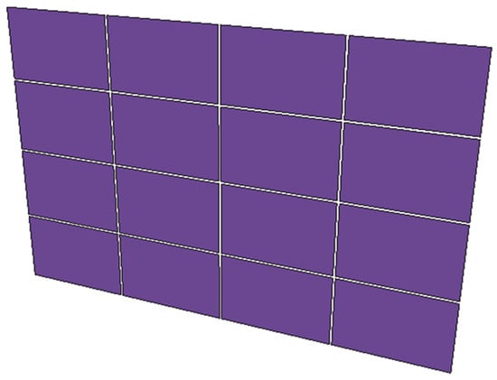
Figure 7.
Approximation and isometric view of the deciduous climbers.
Table 5.
Average monthly bioshading coefficients of the adopted deciduous climbers [68].
Based on the values shown, it can be concluded that the intuitive leafing of plants takes place during May (V. coignetiae, H. lupulus, and A. macrophylla) and June (W. sinensis). The benefits are maximal in the period from June to October (V. coignetiae), from June to November (H. lupulus and A. macrophylla), and from July to December (W. sinensis). Leaf fall, depending on the type of plant, occurs during October (V. coignetiae), November (H. lupulus and A. macrophylla), and December (W. sinensis).
The geometric and graphic approximation of the deciduous climbers was performed in Google SketchUp using the New EnergyPlus Shading Group tool from the Legacy OpenStudio palette, creating flat panels that fill the space between the wooden planks (Figure 7). The same methodology was applied during the graphic design of the pergolas. These two elements differ by the BSC parameter (for deciduous climbers, Table 5), which is defined in the EnergyPlus software.
2.3. Location Parameters
The thermal performance of all thermo-technical systems (applies to bioclimatic-passive solar systems) in the analyzed building, during the year, is monitored depending on the meteorological conditions for two characteristic locations: Kragujevac town (an area with a moderate continental climate, Table 6) and Kielce town (an area with a continental climate, Table 7).
Table 6.
Average monthly meteorological data for Kragujevac [69].
Table 7.
Average monthly meteorological data for Kielce [69].
Kragujevac (latitude is Φ = 44.02° N, longitude is θ = 20.92° E, and time zone is tz = +1 h) is a town in central Serbia (about 100 km south of Belgrade). Town elevation is el = 185 m. The climate is moderate continental (Table 6).
2.4. Analyzed Scenarios
Figure 8 describes two basic simulation scenarios. In the first case (Figure 8a), numerical simulations are conducted on the classic analyzed building. It is a building without additional construction elements. This building serves as a control, as all subsequent modifications and improvements, utilizing various bioclimatic and passive elements, are compared against its performance.
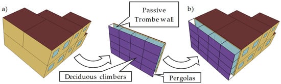
Figure 8.
Analyzed building: (a) without and (b) with bioclimatic-passive elements.
In the second case (Figure 8b), a potential solution that has not been explored in the existing literature as a measure of energy efficiency in buildings is presented. It involves a building equipped with various elements classified by the profession as passive, bioclimatic, green, and environmentally friendly. Measures have been implemented that complement each other, creating the potential for the building to gain energy and environmental benefits throughout the year: (1) PTW in the winter season, and (2) pergolas and deciduous climbers in the summer season.
To better understand the opportunities and barriers that such systems can offer, this paper uses real-time data from two major climate regions in Europe (Table 6 and Table 7). The building designs are justified by adherence to the National Energy Efficiency Rulebooks. The additional bioclimatic-passive elements are estimated using experimental data, available technical solutions, and market conditions (Section 2.2). Additionally, the paper examines four types of plants and three types of glazing (Figure 9, Table 8). This approach aims to use numerical simulations to produce results of practical scientific relevance.
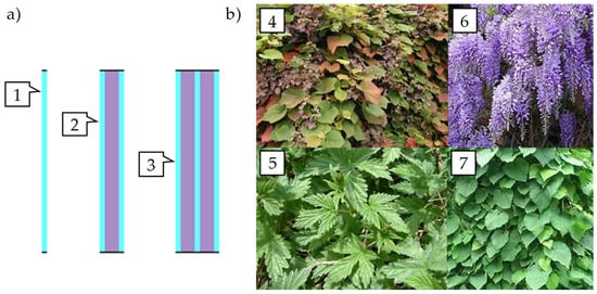
Figure 9.
Simulation scenarios: (a) glazing and (b) plant types. Legend: 1—single-glazing, 2—double-glazing, 3—triple-glazing, 4—V. coignetiae, 5—H. lupulus, 6—W. sinensis, and 7—A. macrophylla.
Table 8.
Variables used in numerical simulations.
2.5. Mathematical Model
2.5.1. Space Heating
Useful heating energy consumption (useful, final, primary, embodied, and full energy consumptions, CO2 emissions, and monetary costs are tracked on an annual basis (Section 2.5 and Section 3)) (from electricity) Eheat,use [kWh] in the analyzed building can be calculated as Equation (1):
where: Eheat,TZ [kWh]—total heating energy losses (transmission and ventilation) for the one thermal zone in the analyzed building [67], Eihg [kWh]—energy production from the internal heat gains (people, electric equipment and lighting) for the one thermal zone in the analyzed building (Section 2.2), and EPTW [kWh]—energy production from the passive Trombe wall in the analyzed building (Equation (2)).
where: EPTW,abs [kWh]—total absorbed solar energy (radiation) by the passive Trombe wall in the analyzed building (Figure 10, Equation (3)), and EPTW,loss [kWh]—total heating energy losses from the passive Trombe wall in the analyzed building (Figure 11, Equation (4)).
where: EPTW,beam [kWh]—absorbed beam solar energy (radiation) by the passive Trombe wall in the analyzed building, EPTW,diff [kWh]—absorbed diffuse solar energy (radiation) by the passive Trombe wall in the analyzed building, EPTW,refl [kWh]—absorbed reflected solar energy (radiation) by the passive Trombe wall in the analyzed building, QPTW,loss [W]—total heat losses from the passive Trombe wall in the analyzed building, APTW [m2]—area of the passive Trombe wall in the analyzed building, ΣUPTW,loss [W/m2K]—total heat transfer coefficient for the passive Trombe wall in the analyzed building, TSC [°C]—absolute temperature of the selective coating surface for the passive Trombe wall in the analyzed building, and Tair [°C]—absolute temperature of the external air.
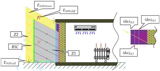
Figure 10.
Total absorbed solar energy (radiation) by the passive Trombe wall. Legend: Z1—shading zone, Z2—sun-exposed zone, (dα)GL1 [-]—optical efficiency of the first glazing layer for the passive Trombe wall in the analyzed building, (dα)GL2 [-]—optical efficiency of the second glazing layer for the passive Trombe wall in the analyzed building, and (dα)GL3 [-]—optical efficiency of the third glazing layer for the passive Trombe wall in the analyzed building.
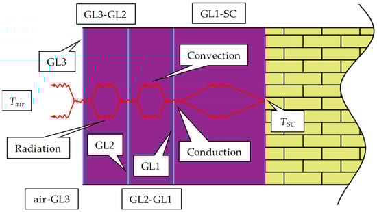
Figure 11.
Total heating energy losses from the passive Trombe wall.
The absorbed beam (Equation (5)), diffuse (Equation (6)), and reflected (Equation (7)) solar energy (radiation) are, respectively:
where: (dα)beam [-]—optical efficiency of the beam solar energy (radiation) for the passive Trombe wall in the analyzed building (Table 9), ESUN,beam [kWh]—incoming beam solar energy (radiation) for the passive Trombe wall in the analyzed building (Table 10), cosβ [rad]—solar incident angle for the passive Trombe wall in the analyzed building, cosZ [rad]—solar incident angle for the horizontal surface, VF [-]—view factor, (dα)diff [-]—optical efficiency of the diffuse solar energy (radiation) for the passive Trombe wall in the analyzed building (Table 9), ESUN,diff [kWh]—incoming diffuse solar energy (radiation) for the passive Trombe wall in the analyzed building (Table 10), (dα)refl [-]—optical efficiency of the reflected solar energy (radiation) for the passive Trombe wall in the analyzed building (Table 9), a [-]—ground albedo, and ESUN,refl [kWh]—incoming reflected solar energy (radiation) for the passive Trombe wall in the analyzed building (Table 10).
Table 9.
Correlation between optical efficiency and glazing type for the passive Trombe wall.
Table 10.
Correlation between bioshading coefficient and incoming solar energy (radiation) for the passive Trombe wall.
Value ΣUPTW,loss can be calculated as the sum of the UPTW,loss,frn and UPTW,loss,edg values using Equation (8):
where: UPTW,loss,frn [W/m2K]—heat transfer coefficient for the front side of the passive Trombe wall in the analyzed building (Table 11), and UPTW,loss,edg [W/m2K]—heat transfer coefficient for the edges of the passive Trombe wall in the analyzed building.
Table 11.
Correlation between heat transfer coefficient and glazing type for the passive Trombe wall.
Final Eheat,fin [kWh] (Equation (9)) and primary Eheat,pry [kWh] (Equation (10)) heating energy consumption (from electricity) are as follows:
where: Rel [-]—primary conversion factor for electricity (Section 2.5.5).
2.5.2. Space Cooling
Useful cooling energy consumption (from electricity) Ecool,use [kWh] in the analyzed building can be calculated using Equation (11):
where Ecool,TZ [kWh]—total cooling energy gains (transmission and ventilation) for the one thermal zone in the analyzed building [67].
Analogous to heating energy, final Ecool,fin [kWh] (Equation (12)) and primary Ecool,pry [kWh] (Equation (13)) cooling energy consumption (from electricity) are as follows:
2.5.3. Energy Indicators
Total useful Etot,use [kWh] (Equation (14)), final Etot,fin [kWh] (Equation (15)), and primary Etot,pry [kWh] (Equation (16)) energy consumption (from electricity) for space heating and cooling in the analyzed building are as follows:
Total embodied energy Etot,emb [kWh] (Equation (17)) for the novel bioclimatic-passive architecture concept in the analyzed building is the sum of the embodied energy for the passive Trombe wall Eemb,PTW [kWh] (Equation (18)) and embodied energy for the wooden pergolas Eemb,PER [kWh] (Equation (19)) (embodied energy for the deciduous climbers can be eliminated):
where: Eemb,MW [kWh]—embodied energy of the massive wall for the passive Trombe wall in the analyzed building, Eemb,SC [kWh]—embodied energy of the selective coating for the passive Trombe wall in the analyzed building, Eemb,GL [kWh]—embodied energy of the glazing for the passive Trombe wall in the analyzed building, eemb,MW [kWh/kg]—specific embodied energy of the massive wall for the passive Trombe wall in the analyzed building (Table 12), mMW [kg]—mass of the massive wall for the passive Trombe wall in the analyzed building (Table 12), eemb,SC [kWh/kg]—specific embodied energy of the selective coating for the passive Trombe wall in the analyzed building (Table 12), mSC [kg]—mass of the selective coating for the passive Trombe wall in the analyzed building (Table 12), nGL [-]—number of the glazing for the passive Trombe wall in the analyzed building (Table 12), eemb,GL [kWh/kg]—specific embodied energy of the glazing for the passive Trombe wall in the analyzed building (Table 12), mGL [kg]—mass of the glazing for the passive Trombe wall in the analyzed building (Table 12), eemb,PER [kWh/kg]—specific embodied energy of the pergolas in the analyzed building (Table 12), and mPER [kg]—mass of the pergolas in the analyzed building (Table 12).
Table 12.
Correlation between embodied energy, investment costs, and bioclimatic-passive elements in the analyzed building [70].
At the end, full energy Efull [kWh] consumption (from electricity) for space heating and cooling in the analyzed building can be presented as Equation (20):
2.5.4. Environmental Indicators
The main parameter representing this group of indicators is CO2 emissions. In this case, for the needs of space heating and cooling, the total CO2 emissions Mtot,CO2 [kg] can be determined using Equation (21):
where: Mheat,CO2 [kg]—CO2 emissions for the space heating in the analyzed building, Mcool,CO2 [kg]—CO2 emissions for the space cooling in the analyzed building, and gCO2 [kg/kWh]—specific CO2 emissions for the electricity in the analyzed building (Section 2.5.5).
2.5.5. Economic Indicators
Total investment costs Ytot,inv [EUR] (without taking deciduous climbers into account) are as follows (Equation (22)):
where: Yinv,PTW [EUR]—investment costs for the passive Trombe wall in the analyzed building (Section 2.5.3), Yinv,PER [EUR]—investment costs for the pergolas in the analyzed building (Section 2.5.3), Yinv,MW [EUR]—investment costs of the massive wall for the passive Trombe wall in the analyzed building (Section 2.5.3), Yinv,SC [EUR]—investment costs of the selective coating for the passive Trombe wall in the analyzed building (Section 2.5.3), and Yinv,GL [EUR]—investment costs of the glazing for the passive Trombe wall in the analyzed building (Section 2.5.3).
The last (economic) indicator is the payback period PB [years]. This indicator is shown in Equation (23):
where: Yel,before [EUR]—electricity price for the heating and cooling before implementation of the bioclimatic-passive elements in the analyzed building, Yel,after [EUR]—electricity price for the heating and cooling after implementation of the bioclimatic-passive elements in the analyzed building, yel [EUR/kWh]—specific price for the electricity in the analyzed building (Table 13), Etot,fin,before [kWh]—total final energy consumption (from electricity) for space heating and cooling before implementation of the bioclimatic-passive elements in the analyzed building, and Etot,fin,after [kWh]—total final energy consumption (from electricity) for space heating and cooling after implementation of the bioclimatic-passive elements in the analyzed building.
Table 13.
Specific energy, environmental, and economic indicators for the bioclimatic-passive elements in the analyzed building.
3. Results and Discussion
Table 14 shows the values of Etot,use, Etot,fin, and Etot,pry (Section 2.5.3), Mtot,CO2 (Section 2.5.4), and Yel,before (Section 2.5.5) for the analyzed building without (Section 2.4) bioclimatic-passive elements for two adopted climate zones (Section 2.3): moderate continental climate (Kragujevac) and continental climate (Kielce).
Table 14.
Energy, environmental, and economic indicators in the analyzed building without bioclimatic-passive elements, depending on location parameters.
The numerical results (Table 14) on the initial geometric building model (the classic building, Figure 8a) demonstrate that a moderate continental climate, in terms of energy, is more favorable to its tenants. Namely, the energy needs of the analyzed building without bioclimatic-passive elements, located in Kielce, are 18.64% (for Etot,use), 46.06% (for Etot,fin), and 35.54% (for Etot,pry) higher than in the case of the same building located in Kragujevac. CO2 emissions from the Polish building are 93.85% higher, while the price is 2.83 times higher.
Ecool,use makes up 37.17% (for Kragujevac) and 8.75% (for Kielce) of the Etot,use. The structure additionally changes in favor of heating if the share of Ecool,fin in Etot,fin is followed: 18.17% (for Kragujevac) and 3.47% (for Kielce). In the remaining cases (Etot,pry, Mtot,CO2, and Yel,before), the share of Ecool,fin = Ecool,pry = Mtot,CO2 = Yel,before does not change, which is also logical if specific indicators are taken into account (Section 2.5.5).
Contrary to the parameters shown in Table 14, Table 15 shows Etot,use, Etot,fin, Etot,pry, Mtot,CO2, and Yel,after in the analyzed building with bioclimatic-passive elements, located in Kragujevac, taking into account two additional groups of variables: (1) three types of glazing and (2) four types of deciduous climbers. Table 16 shows the same parameters for another location, i.e., Kielce town. Pergolas are also included in all the mentioned numerical scenarios.
Table 15.
Energy, environmental, and economic indicators in the analyzed building with bioclimatic-passive elements located in Kragujevac.
Table 16.
Energy, environmental, and economic indicators in the analyzed building with bioclimatic-passive elements located in Kielce.
In all considered glazing scenarios (Table 15), it was shown that, in comparison with other types of deciduous climbers, V. coignetiae contributes the most to the reduction in Etot,use, Etot,fin, and Etot,pry consumptions. The same goes for Mtot,CO2 and Yel,after indicators. On the other hand, for the tenants of the analyzed building, the least favorable option is the use of W. sinensis. If, for example, the mentioned two climbers are compared using the Yel,after indicator, the number values in the case of W. sinensis are higher than V. coignetiae by 7.14% (single-glazing), 9.12% (double-glazing), and 8.65% (triple-glazing). The best results are achieved by combining V. coignetiae and triple glazing, because in that case the indicators are, respectively (Table 15), Etot,use = 6386.13 kWh, Etot,fin = 3879.05 kWh, Etot,pry = 9697.63 kWh, Mtot,CO2 = 5139.74 kg, and Yel,after = EUR 481. If the results from Table 15 are compared with the results for Kragujevac from Table 14, it is clear that the option involving combining deciduous climbers and single-glazing cannot be considered an acceptable solution, i.e., a solution that can have practical and wider commercial use application.
The same deciduous climbers are the most energetically acceptable (V. coignetiae) and least favorable (W. sinensis) options in the continental climate area, i.e., Kielce town (Table 16). From the attached table, it can be concluded that the biggest differences are between the following two options: V. coignetiae with triple-glazing (first and best option), and W. sinensis with single-glazing (second and worst option). If this comparison were to be expressed in percentages, the values in the second case are higher by 21.3% (Etot,use) and 33.22% (Etot,fin, Etot,pry, Mtot,CO2, and Yel,after). Compared to the basic building model (Table 14), better results can be expected (by all parameters) when deciduous climbers are placed in front of triple-glazed PTW.
The hourly external (tair) and internal (tPTW, tLR, tBR1, and tBR2) temperatures during the year in the analyzed building with pergolas, V. coignetiae, and triple-glazed PTW (best solution based on Table 15 and Table 16) located in Kragujevac (Figure 12) and Kielce (Figure 13) are shown below.
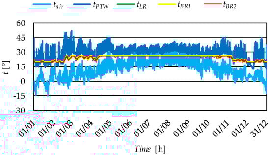
Figure 12.
Hourly external and internal temperatures during the year in the analyzed building with bioclimatic-passive elements (pergolas, V. coignetiae, and triple-glazed passive Trombe wall) located in Kragujevac.
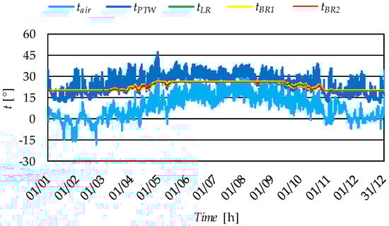
Figure 13.
Hourly external and internal temperatures during the year in the analyzed building with bioclimatic-passive elements (pergolas, V. coignetiae, and triple-glazed passive Trombe wall) located in Kielce.
In Figure 12 and Figure 13, it can be seen that the temperature in PTW (as non-treated TZ) is always above tair (valid for both locations). The maximum measured tPTW temperatures were 36.96 °C (for Kragujevac) and 34.68 °C (for Kielce). Due to the fact that Kragujevac is located in a moderate continental climate area, the temperature differences (Δt = tPTW-tair) are smaller than in the case of Kielce, a place in the continental climate area. Temperatures in thermally treated TZs (LR, BR1, and BR2) are within the permissible limits defined by theat = 20 °C and tcool = 26 °C. In the transition periods of the year, it can be observed that these temperatures are between 20 and 26 °C, which means that the heat gains from the passive solar systems are sufficient to not engage the heating or cooling system. This time range is shorter in Figure 13, which is also explained by climatic and meteorological conditions. For the same reasons (by comparing the results with Figure 12 and Figure 13), it can be concluded that the cooling season in Kragujevac is longer than the cooling season in Kielce.
The next table (Table 17) summarizes embodied energy Etot,emb and investment costs Ytot,inv in the analyzed building depending on the number of the glazing layer.
Table 17.
Embodied energy and investment costs for different types of passive Trombe walls in the analyzed building.
Considering the various values from Table 15, Table 16 and Table 17, Table 18 shows the remaining two indicators: one energy (Efull) and one economic (PB). The results are shown for all analyzed cases, which means that they take into account the types of glazing, deciduous climbers, and locations.
Table 18.
Full energy consumption and payback period in the analyzed building, depending on the simulation scenario.
The simulation results shown in Table 18 again confirm that V. coignetiae has the greatest energy, environmental, and economic potential compared to H. lupulus, W. sinensis, and A. macrophylla for application both in moderate continental and continental zones.
If this plant were used within the proposed concept, the Efull indicator would still favor the Serbian building. In other words, the Efull indicator for a Polish building would be higher by (Table 18): 45.39% (V. coignetiae and single-glazing), 41.63% (V. coignetiae and double-glazing), and 36.2% (V. coignetiae and triple-glazing). In the Serbian case, Efull is higher by 11.82% (V. coignetiae and double-glazing) and by 16.65% (V. coignetiae and triple-glazing) compared to the base case (V. coignetiae and single-glazing). In the Polish case, these differences are even more pronounced compared to V. coignetiae and single-glazing: 14.79% (V. coignetiae and double-glazing) and 24.51% (V. coignetiae and triple-glazing).
The results of the payback period calculation indicate that the proposed concept should be approached carefully because the payback period can be very long. In some cases, it can be even longer than 50 years. This can be explained by the fact that deciduous climbers cannot, in practice, ensure complete solar insolation (during the winter season) and complete solar shading (during the summer season) of passive Trombe walls. There are also economic circumstances that contribute to a certain extent to the extension of this period.
Table 18 also shows that, in some cases, the payback period can be half as short (20–30 years for Kielce), which represents a positive impetus for the future development of the proposed concept. For this bioclimatic-passive architecture concept to be economically justified in the future, attention should be directed toward amortizing the market prices of key components: selective coatings, glazing, deciduous climbers, pergola materials, etc. The involvement of multiple government sectors should also be considered—subsidizing the implementation of passive measures to achieve energy efficiency could become a good practice. Using recycled materials, adopting a responsible strategy in the design phase (which includes planting climbers before installing the PTW), and ensuring proper maintenance and management of all components are also very important. Planting climbers in front of the PTW would also create a natural shield that would protect the glass layers from weather conditions and mechanical damage.
4. Conclusions
This paper investigated the impact of passive, bioclimatic, green solar systems for heating (passive Trombe walls) and cooling (pergolas and deciduous climbers) on the performance of residential buildings located in two different and dominant European climate areas: moderate continental (Kragujevac) and continental (Kielce). This paper aims to show a novel building concept, unknown in the literature.
The research subject was residential buildings equipped with electric equipment, lighting, water heating, individual electric heaters (for space heating), and individual air-conditioner units (for space cooling).
The analyzed building was created in compliance with the Serbian and Polish rulebooks. The proposed energy-efficient building concept was numerically (with Google SketchUp and EnergyPlus) analyzed and tested, using three passive Trombe wall types (single-glazed, double-glazed, and triple-glazed) and four deciduous climber types (V. coignetiae, H. lupulus, W. sinensis, and A. macrophylla).
The initial results showed that the total useful, final, and primary energy consumption, CO2 emission, and investment costs in the Serbian residential building without bioclimatic-passive elements are 5931.21 kWh, 4647.48 kWh, 11,618.7 kWh, 6157.91 kg, and EUR 576.29. On the other side, the same energy, environmental, and economic indicators for the Polish residential building, also bioclimatic-passive elements, are, respectively, 7036.65 kWh, 6788.06 kWh. 15,748.3 kWh, 11,937.21 kg, and EUR 1629.13.
By applying bioclimatic-passive elements, such as pergolas, V. coignetiae, and triple-glazed passive Trombe walls, the best energy results are achieved: Efull = 11,074.23 kWh (for Kragujevac) and Efull = 15,083.32 kWh (for Kielce). Compared to the initial model of the house, the CO2 emission (economic indicator) can be reduced by 19.81% (for Kragujevac) and 14.89% (for Kragujevac). Taking into account the current market conditions, the results showed that the payback period (economic indicator) is not yet on the side of the end users (tenants in the analyzed building), but also that there is a huge space for progress to commercialize the proposed concept, due to, as already stated, positive energy and environmental effects.
Based on all of the above, the future directions of investigation should focus on the next critical points: (1) deeper analysis of the use of different deciduous climbers (bioshading coefficients, CO2 reductions, vegetative developments, etc.); (2) optimization of geometric, optical, and thermal performance of the combined application of bioclimatic-passive elements; (3) the possibility of implementing other passive solar systems whose positive characteristics have been proven in the literature (for example overhangs); (4) researching the potential of application in other regions of Europe and the world; and (5) the possibility of implementing active Trombe walls.
Author Contributions
Conceptualization, A.N. and R.K.; methodology, A.N. and R.K.; investigation, A.N. and R.K.; data curation, A.N.; writing—original draft preparation, A.N. and R.K.; visualization, A.N.; project administration, R.K. All authors have read and agreed to the published version of the manuscript.
Funding
This research received no external funding.
Institutional Review Board Statement
Not applicable.
Informed Consent Statement
Not applicable.
Data Availability Statement
The original contributions presented in the study are included in the article; further inquiries can be directed to the corresponding author.
Conflicts of Interest
The authors declare no conflicts of interest.
Nomenclature
| Nomenclature: | ||
| A | Area | [m2] |
| a | Ground albedo | [-] |
| BSC | Bioshading coefficients | [-] |
| c | Wind speed | [m/s] |
| COP | Coefficient of performance | [-] |
| cosZ | Solar incident angle on the horizontal plane | [rad] |
| cosβ | Solar incident angle for the passive Trombe wall | [rad] |
| cp | Specific heat | [J/kgK] |
| D | Wind direction | [°] |
| d | Transmissivity | [-] |
| E | Energy | [kWh] |
| e | Specific energy | [kWh/m2] |
| el | Elevation | [m] |
| f | Form factor | [1/m] |
| g | Specific CO2 emission | [kg/kWh] |
| H | Solar irradiance on the horizontal plane | [W/m2] |
| h | Heat transfer coefficient | [W/m2K] |
| M | CO2 emissions | [kg] |
| m | Mass | [kg] |
| n | Specific air change | [m3/h/m2] |
| p | Specific people indicator | [m2/per] |
| PB | Payback period | [years] |
| Q | Power | [W] |
| q | Specific metabolic activities | [W/per] |
| R | Primary conversion factor | [-] |
| S | Energy savings | [%] |
| SR | Solar reflectance | [-] |
| ST | Solar transmittance | [-] |
| T | Absolute temperature | [K] |
| t | Temperature | [°C] |
| tz | Time zone | [h] |
| U | Heat transfer coefficient | [W/m2K] |
| V | Volume | [m3] |
| VF | View factor | [-] |
| WW | Window–wall ratio | [%] |
| Y | Costs | [EUR] |
| y | Specific costs | [EUR/kWh] |
| Greek letters: | ||
| α | Absorptance | [-] |
| β | Inclination angle | [-] |
| Δ | Temperature difference | [°C] |
| δ | Thickness | [mm] |
| ε | Emissivity | [-] |
| η | Thermal efficiency | [-] |
| θ | Longitude | [°] |
| λ | Thermal conductivity | [W/mK] |
| ρ | Density | [kg/m3] |
| τ | Time period | [h] |
| Φ | Latitude | [°] |
| φ | Relative humidity | [%] |
| Subscripts: | ||
| abs | Absorbed | |
| acu | Air-conditioned unit | |
| after | After implementation | |
| air | Air | |
| beam | Beam | |
| before | Before implementation | |
| cool | Space cooling | |
| CO2 | Greenhouse gases | |
| DG | Double-glazing | |
| diff | Diffuse | |
| ed | External door | |
| edg | Edges | |
| eel | Electric equipment and lighting | |
| efl | External floor | |
| el | Electricity | |
| emb | Embodied | |
| ew | External wall | |
| fin | Final | |
| fl | Floor | |
| fr | Flat roof | |
| frn | Front | |
| full | Full | |
| GL | Glazing layer | |
| GL1 | Glazing layer 1 | |
| GL2 | Glazing layer 2 | |
| GL3 | Glazing layer 3 | |
| heat | Space heating | |
| ihg | Internal heat gains | |
| inv | Investment | |
| loss | Losses | |
| MW | Massive wall | |
| PER | Pergolas | |
| pl | People | |
| POL | Poland | |
| pry | Primary | |
| rad | Radiator | |
| refl | Reflection | |
| SC | Selective coating | |
| SG | Single-glazing | |
| SRB | Serbia | |
| SUN | Sun | |
| TG | Triple-glazing | |
| tot | Total | |
| use | Useful | |
| wd | Wind | |
| wh | Water heating | |
| ww | Window | |
| Abbreviation: | ||
| ATW | Active Trombe wall | |
| BR1 | Bedroom 1 | |
| BR2 | Bedroom 2 | |
| BT | Bathroom | |
| H1 | Hall 1 | |
| H2 | Hall 2 | |
| K | Kitchen | |
| LR | Living room | |
| np | Not possible | |
| PCM | Phase change material | |
| PTW | Passive Trombe wall | |
| RESs | Renewable energy sources | |
| RBS | Residential building sector | |
| S | Staircase | |
| SR | Study room | |
| T | Toilet | |
| TW | Trombe wall | |
| TZ | Thermal zone | |
| Z1 | Shading zone | |
| Z2 | Sun-exposed zone | |
References
- Vijayan, D.S.; Sivasuriyan, A.; Patchamuthu, P.; Jayaseelan, R. Thermal performance of energy-efficient buildings for sustainable development. Environ. Sci. Pollut. Res. 2022, 29, 51130–51142. [Google Scholar] [CrossRef] [PubMed]
- Majewski, G.; Telejko, M.; Orman, Ł.J. Preliminary results of thermal comfort analysis in selected buildings. E3S Web Conf. 2017, 17, 00056. [Google Scholar] [CrossRef]
- Gan, V.J.; Lo, I.M.; Ma, J.; Tse, K.T.; Cheng, J.C.; Chan, C.M. Simulation optimisation towards energy efficient green buildings: Current status and future trends. J. Clean. Prod. 2020, 254, 120012. [Google Scholar] [CrossRef]
- Lewandowski, K. Modern energy sources for sustainable buildings: Innovations and energy efficiency in green construction. Energies 2025, 18, 1121. [Google Scholar] [CrossRef]
- Ma, Z.; Awan, M.B.; Lu, M.; Li, S.; Aziz, M.S.; Zhou, X.; Du, H.; Sha, X.; Li, Y. An overview of emerging and sustainable technologies for increased energy efficiency and carbon emission mitigation in buildings. Buildings 2023, 13, 2658. [Google Scholar] [CrossRef]
- Contreras, G.S.; Lezcano, R.A.G.; Fernández, E.J.L.; Concepción, M.; Gutiérrez, P. Architecture learns from nature: The influence of biomimicry and biophilic design in building. Mod. Appl. Sci. 2023, 17, 58. [Google Scholar] [CrossRef]
- Moriarty, P.; Honnery, D. Energy efficiency or conservation for mitigating climate change? Energies 2019, 12, 3543. [Google Scholar] [CrossRef]
- Nešović, A.; Kowalik, R.; Bojović, M.; Janaszek, A.; Adamczak, S. Elevational Earth-Sheltered Buildings with Horizontal Overhang Photovoltaic-Integrated Panels—New Energy-Plus Building Concept in the Territory of Serbia. Energies 2024, 17, 2100. [Google Scholar] [CrossRef]
- Nagaraju, D.; Mendu, S.S.; Chinta, N.D. A numerical approach to design building envelope for energy efficient building. Int. J. Interact. Des. Manuf. 2025, 19, 199–218. [Google Scholar] [CrossRef]
- Anselm, A.J. Earth shelters: A review of energy conservation properties in earth sheltered housing. Energy Conserv. 2012, 31, 125–148. [Google Scholar]
- Radek, N.; Pietraszek, J.; Gądek-Moszczak, A.; Orman, Ł.J.; Szczotok, A. The Morphology and Mechanical Properties of ESD Coatings before and after Laser Beam Machining. Materials 2020, 13, 2331. [Google Scholar] [CrossRef]
- Bulmez, A.M.; Brezeanu, A.I.; Dragomir, G.; Fratu, M.; Iordan, N.F.; Bolocan, S.I.; Rozorea, L.; Popa, E.C.; Năstase, G. CFD analysis for a new Trombe wall concept. Buildings 2024, 14, 579. [Google Scholar] [CrossRef]
- Briga Sá, A.C.; Martins, A.; Boaventura-Cunha, J.; Lanzinha, J.C.; Paiva, A. An analytical approach to assess the influence of the massive wall material, thickness and ventilation system on the Trombe wall thermal performance. J. Build. Phys. 2018, 41, 445–468. [Google Scholar] [CrossRef]
- Ghamari, M.; Sundaram, S. Solar wall technology and its impact on building performance. Energies 2024, 17, 1075. [Google Scholar] [CrossRef]
- Prozuments, A.; Borodinecs, A.; Bebre, G.; Bajare, D. A review on Trombe wall technology feasibility and applications. Sustainability 2023, 15, 3914. [Google Scholar] [CrossRef]
- Mokni, A.; Lashin, A.; Ammar, M.; Mhiri, H. Thermal analysis of a Trombe wall in various climatic conditions: An experimental study. Sol. Energy 2022, 243, 247–263. [Google Scholar] [CrossRef]
- Xiao, Y.; Yang, Q.; Fei, F.; Li, K.; Jiang, Y.; Zhang, Y.; Ma, Q. Review of Trombe wall technology: Trends in optimization. Renew. Sustain. Energy Rev. 2024, 200, 114503. [Google Scholar] [CrossRef]
- Zhang, L.; Cheng, J.; Liu, F.; Li, H.; Dong, Z.; Zhang, X.; Tian, C. Interaction effect of room size and opening on Trombe wall performance in Sichuan–Tibet alpine valley areas. Appl. Sci. 2022, 12, 5260. [Google Scholar] [CrossRef]
- Ahmed, O.K. Recent advances in photovoltaic-Trombe wall system: A review. Renew. Energy Technol. Appl. 2020. [Google Scholar]
- Wu, S.Y.; Zheng, H.; Xiao, L. Effect of forced ventilation strategy on the thermal performance of finned-Trombe wall. J. Build. Eng. 2024, 87, 109021. [Google Scholar] [CrossRef]
- Yedder, R.B.; Du, Z.G.; Bilgen, E. Numerical study of laminar natural convection in composite Trombe wall systems. Sol. Wind Technol. 1990, 7, 675–683. [Google Scholar] [CrossRef]
- Ormiston, S.J.; Raithby, G.D.; Hollands, K.G.T. Numerical predictions of natural convection in a Trombe wall system. Int. J. Heat Mass Transf. 1986, 29, 869–877. [Google Scholar] [CrossRef]
- Mo, W.; Zhang, G.; Yao, X.; Li, Q.; DeBacker, B.J. Assessment of passive solar heating systems’ energy-saving potential across varied climatic conditions: The development of the passive solar heating indicator (PSHI). Buildings 2024, 14, 1364. [Google Scholar] [CrossRef]
- Gil-Martín, L.M.; Gómez-Guzmán, A.; Peña-García, A. Use of diffusers materials to improve the homogeneity of sunlight under pergolas installed in road tunnels portals for energy savings. Tunn. Undergr. Space Technol. 2015, 48, 123–128. [Google Scholar] [CrossRef]
- Inuthai, J. Flowering and fruiting phenology of herbs, climbers, shrubs, and trees in the deciduous dipterocarp forest of Northern Thailand. J. Ecol. Environ. 2023, 47, 134–145. [Google Scholar] [CrossRef]
- Hunter, A.M.; Williams, N.S.; Rayner, J.P.; Aye, L.; Hes, D.; Livesley, S.J. Quantifying the thermal performance of green façades: A critical review. Ecol. Eng. 2014, 63, 102–113. [Google Scholar] [CrossRef]
- Lee, L.S.; Jim, C.Y. Multidimensional analysis of temporal and layered microclimatic behavior of subtropical climber green walls in summer. Urban Ecosyst. 2020, 23, 389–402. [Google Scholar] [CrossRef]
- Ip, K.; Lam, M.; Miller, A. Shading performance of a vertical deciduous climbing plant canopy. Build. Environ. 2010, 45, 81–88. [Google Scholar] [CrossRef]
- de Oliveira, M.J.M. Towards a bio-shading system concept design methodology. Ph.D. Thesis, ISCTE-Instituto Universitário de Lisboa, Lisbon, Portugal, 2019. [Google Scholar]
- Dragićević, S.M.; Lambić, M.R. Numerical study of a modified Trombe wall solar collector system. Therm. Sci. 2009, 13, 195–204. [Google Scholar] [CrossRef]
- Dragićević, S.; Lambic, M. Influence of constructive and operating parameters on a modified Trombe wall efficiency. Arch. Civ. Mech. Eng. 2011, 11, 825–838. [Google Scholar] [CrossRef]
- Malešević, J.; Milovanović, M.; Đorđević, S.; Bojic, M.; Lukic, N. The influence of the Trombe wall on energy consumption for heating and cooling of net zero energy house. In Proceedings of the 7th International Quality Conference, Kragujevac, Serbia, 24 May 2013; pp. 237–247. [Google Scholar]
- Bojić, M.; Johannes, K.; Kuznik, F. Optimizing energy and environmental performance of passive Trombe wall. Energy Build. 2014, 70, 279–286. [Google Scholar] [CrossRef]
- Bajc, T.; Todorović, M.N.; Svorcan, J. CFD analyses for passive house with Trombe wall and impact to energy demand. Energy Build. 2015, 98, 39–44. [Google Scholar] [CrossRef]
- Randjelovic, D.; Vasov, M.; Ignjatovic, M.; Stojiljkovic, M.; Bogdanovic, V. Investigation of a passive design approach for a building facility: A case study. Energy Sources Part A Recover. Util. Environ. Eff. 2025, 47, 8890–8908. [Google Scholar] [CrossRef]
- Vukadinović, A.; Radosavljević, J.; Đorðević, A. Impact of green roofing on the energy performance of a detached passive residential building with a Trombe wall. Ann. Fac. Eng. Hunedoara 2022, 20, 99–102. [Google Scholar]
- Šetrajčić, J.; Vučenović, S.; Vojnović, N.; Ilić, D. Simulation of the insulation properties by modification of the Trombe wall. Innov. Mech. Eng. 2023, 2, 79–88.unspecified. [Google Scholar]
- Nešović, A.; Cvetković, D. Traditional Serbian Country Cottage Equipped With The Passive Trombe Wall. Agric. Eng. 2024, 49, 43–51. [Google Scholar] [CrossRef]
- Szyszka, J.; Kogut, J.; Skrzypczak, I.; Kokoszka, W. Selective internal heat distribution in modified Trombe wall. IOP Conf. Ser. Earth Environ. Sci. 2017, 95, 042018. [Google Scholar] [CrossRef]
- Błotny, J.; Nemś, M. Analysis of the impact of the construction of a Trombe wall on the thermal comfort in a building located in Wrocław, Poland. Atmosphere 2019, 10, 761. [Google Scholar] [CrossRef]
- Szyszka, J. Experimental evaluation of the heat balance of an interactive glass wall in a heating season. Energies 2020, 13, 632. [Google Scholar] [CrossRef]
- Oltarzewska, A.; Krawczyk, D.A. Trombe walls–characteristic, overview and simple case study for different climate conditions. In IOP Conf. Ser. Earth Environ. Sci. 2021, 943, 012027. [Google Scholar]
- Lichołai, L.; Starakiewicz, A.; Krasoń, J.; Miąsik, P. The influence of glazing on the functioning of a Trombe wall containing a phase change material. Energies 2021, 14, 5243. [Google Scholar] [CrossRef]
- Szyszka, J. From direct solar gain to Trombe wall: An overview on past, present and future developments. Energies 2022, 15, 8956. [Google Scholar] [CrossRef]
- Szyszka, J.; Bevilacqua, P.; Bruno, R. A statistical analysis of an innovative concept of Trombe wall by experimental tests. J. Build. Eng. 2022, 62, 105382. [Google Scholar] [CrossRef]
- Dyda, M.; Laudy, A.; Decewicz, P.; Romaniuk, K.; Ciezkowska, M.; Szajewska, A.; Skłodowska, A. Diversity of biodeteriorative bacterial and fungal consortia in winter and summer on historical sandstone of the northern Pergola, Museum of King John III’s Palace at Wilanow, Poland. Appl. Sci. 2021, 11, 620. [Google Scholar] [CrossRef]
- Kopeć, W.; Hanus-Fajerska, E.; Bylina, L. Conceptual design of an urban pocket park located in the site of the occurrence of a nineteenth-century chapel using representatives of local xerothermic vegetation. Environ. 2024, 11, 252. [Google Scholar] [CrossRef]
- Kozłowska, I. Eco-strategies for urban space in historic cities. IOP Conf. Ser. Mater. Sci. Eng. 2019, 471, 102031. [Google Scholar] [CrossRef]
- Babota, F.; Manea, D.L.; Aciu, C.; Munteanu, C.; Cobîrzan, N.; Tămaș-Gavrea, D.R. Determination of optimal dimensions of fixed shadowing systems (pergolas) to reduce energy consumption in buildings in Romania. Procedia Manuf. 2018, 22, 358–363. [Google Scholar] [CrossRef]
- Sadevi, K.K.; Agrawal, A. A study on roof design strategies for energy conservation in Indian buildings. In Proceedings of the International Conference of Architectural Science Association 2019, Roorkee, India, 28–30 November 2019; pp. 781–790. [Google Scholar]
- Alshikh, Z.; Trepci, E.; Rodriguez-Ubinas, E. Sustainable off-site construction in desert environments: Zero-energy houses as case studies. Sustainability 2023, 15, 11909. [Google Scholar] [CrossRef]
- Verheijen, J.; Sans Mateu, O.; Schutten, J.; Zaghal, K. Reducing heat stress with pergolas: Innovative shade solutions for comfortable spaces. Bachelor’s Thesis, Universitat Politècnica de Catalunya, Barcelona, Spain, 2024. [Google Scholar]
- Dimitrijević-Jovanović, D.; Živković, P.; Stevanović, Ž. The impact of the building envelope with the green living systems on the built environment. Therm. Sci. 2018, 22 (Suppl. S4), 1033–1045. [Google Scholar] [CrossRef]
- Savić, S.; Krstić, H.; Šećerov, I.; Dunjić, J. Decreasing the energy demand in public buildings using nature-based solutions: Case studies from Novi Sad (Republic of Serbia) and Osijek (Republic of Croatia). Energy Sustain. Soc. 2024, 14, 23. [Google Scholar] [CrossRef]
- Jovanović, D.D.; Vasov, M.; Momčilović, A.; Živković, P.; Kostadinović, D. Ventilated green facades as a passive design strategy. Innov. Mech. Eng. 2022, 1, 70–84. [Google Scholar]
- Stevović, I.; Jovanović, J.; Hadrović, S. Green buildings, energy efficiency and raising awareness about environmental protection. In Proceedings of the 9th International Conference, Contemporary Achievements in Civil Engineering, University of Novi Sad, Subotica, Serbia, 25–26 April 2024; pp. 576–584. [Google Scholar]
- Seyrek Şık, C.I.; Woźniczka, A.; Widera, B. A conceptual framework for the design of energy-efficient vertical green façades. Energies 2022, 15, 8069. [Google Scholar] [CrossRef]
- Costa, P.; James, R.W. Constructive use of vegetation in office buildings. Proc. Plants for People Symp. 1995, 23, 1–23. [Google Scholar]
- Skórzewski, W. Potential of using greenery to reduce overheating of buildings in Polish climate conditions. Sci. Rev. Eng. Environ. Sci. 2019, 28, 486. [Google Scholar] [CrossRef]
- Petschek, P.; Gass, S. (Eds.) Constructing Shadows: Pergolas, Pavilions, Tents, Cables, and Plants; Walter de Gruyter: Berlin, Germany, 2012. [Google Scholar]
- Grabowiecki, K.; Jaworski, A.; Niewczas, T.; Belleri, A. Green solutions—Climbing vegetation impact on building–energy balance element. Energy Procedia 2017, 111, 377–386. [Google Scholar] [CrossRef]
- Kaczorek, D.; Bekierski, D. Implementation of the EPBD in Poland—Status in 2020. Available online: https://confluence.external-share.com/content/18675/ca_epbd_v_database_2020_(public)/1861813055/2181701270 (accessed on 22 November 2024).
- Ministry of Construction Transport and Infrastructure of Serbia. Rulebook of Energy Efficiency. Available online: https://www.mgsi.gov.rs (accessed on 14 June 2024).
- 2005 ASHRAE Handbook of Fundamentals; American Society of Heating, Refrigerating and Air-Conditioning Engineers: Atlanta, GA, USA, 2005.
- Lighting Handbook: Reference & Application, 8th ed.; Illuminating Engineering Society of North America: New York, NY, USA, 1993; p. 355.
- Electricity & Electrical Appliances Handbook; Arco Pub. Co: New York, NY, USA, 1976.
- EnergyPlus Software. Engineering Reference. Available online: https://energyplus.net (accessed on 10 June 2024).
- Poiss, M.; Briefer, A.; Scharf, B.; Spörl, P.; Stangl, R. Vertical greenery as natural shading of glass facades: Bioshading coefficients for 4 climbing plant species for assessment of shading performance. Build. Environ. 2025, 283, 113399. [Google Scholar] [CrossRef]
- Climate OneBuilding. Available online: https://climate.onebuilding.org/ (accessed on 23 November 2024).
- Hammond, G.; Jones, C. Embodied energy and carbon in construction materials. Proc. Inst. Civ. Eng. Energy 2008, 161, 87–98. [Google Scholar] [CrossRef]
- Balaras, C.A.; Dascalaki, E.G.; Psarra, I.; Cholewa, T. Primary energy factors for electricity production in Europe. Energies 2020, 16, 93. [Google Scholar] [CrossRef]
- Statista. CO2 Emission for Electricity in Poland. Available online: https://www.statista.com/statistics/1291750/carbon-intensity-power-sector-eu-country/ (accessed on 23 November 2024).
- Serbian Electricity Industry. Available online: https://www.eps.rs (accessed on 25 November 2024).
- Electricity Prices in Poland. Available online: http://cena-pradu.pl (accessed on 25 November 2024).
- Kowalik, R.; Nešović, A.; Cvetković, D.; Janaszek, A.; Kozłowski, T. Numerical Simulation of Climate Change Impact on Energy, Environmental and Economic Performances of Small Single-Family Houses Equipped with Trombe Walls and Fixed Horizontal Overhangs. Energies 2024, 17, 6275. [Google Scholar] [CrossRef]
Disclaimer/Publisher’s Note: The statements, opinions and data contained in all publications are solely those of the individual author(s) and contributor(s) and not of MDPI and/or the editor(s). MDPI and/or the editor(s) disclaim responsibility for any injury to people or property resulting from any ideas, methods, instructions or products referred to in the content. |
© 2025 by the authors. Licensee MDPI, Basel, Switzerland. This article is an open access article distributed under the terms and conditions of the Creative Commons Attribution (CC BY) license (https://creativecommons.org/licenses/by/4.0/).