Abstract
The reinforcement effect of single-reinforced soil support under external loading has limitations, and it is difficult for it to meet engineering stability requirements. Therefore, the stability analysis of slopes supported by a combination of anti-slip piles and reinforced soil under the seismic loading effect needs an in-depth study. Based on the upper-bound theorem of limit analysis and the strength-reduction technique, this study establishes an upper-bound stability model for high–steep slopes that simultaneously considers seismic action and the combined reinforcement of anti-slide piles and reinforced soil. A closed-form safety factor is derived. The theoretical results are validated against published data, demonstrating satisfactory agreement. Finally, the MATLAB R2022a sequential quadratic programming method is used to optimize the objective function, and the Optum G2 2023 software is employed to analyze the factors influencing slope stability due to the interaction between anti-slide piles and geogrids. The research indicates that the horizontal seismic acceleration coefficient kh exhibits a significant negative correlation with the safety factor Fs. Increases in the tensile strength T of the reinforcing materials, the number of layers n, and the length l all significantly improve the safety factor Fs of the reinforced-soil slope. Additionally, as l increases, the potential slip plane of the slope shifts backward. For slope support systems combining anti-slide piles and reinforced soil, when the length of the geogrid is the same, adding anti-slide piles can significantly improve the slope’s safety factor. As anti-slide piles move from the toe to the crest of the slope, the safety factor first decreases and then increases, indicating that the optimal reinforcement position for anti-slide piles should be in the middle to lower part of the slope body. The length of the anti-slip piles should exceed the lowest layer of the geogrid to more effectively utilize the blocking effect of the pile ends on the slip surface. The research findings can provide a theoretical basis and practical guidance for parameter optimization in high–steep slope support engineering.
1. Introduction
As infrastructure construction in China continues to expand, transportation corridors are extending into increasingly rugged mountainous regions. Consequently, the stability of high and steep cut slopes has become a critical concern [1,2,3]. When high-fill embankment construction is carried out in these areas, slope stability is directly related to the safety and durability of the project.
Although only a single-reinforced soil support structure can provide a certain degree of reinforcement, its limitations gradually appear under complex geological conditions and external loads. Moreover, reinforced-soil-retaining walls are subjected to traffic loading and sloping-ground conditions, which frequently lead to backfill sliding along the slope face and to wall deformation or cracking. These defects can trigger landslides and other severe consequences [4,5,6,7]. Under extreme events such as heavy rainfall or earthquakes, their stability is often insufficient for engineering demands. Zhou L. et al. [8] used a finite difference program in numerical simulations to demonstrate that earthquakes significantly reduce slope stability and amplify displacement. Excavation, anti-slip piles, and anchor cables are three treatment measures that can effectively reduce displacement and lower the internal forces in anti-slip piles, thereby improving slope stability during earthquakes and providing important reference for reinforcement strategies. Zucca M. et al. [9] conducted extensive numerical simulations to assess the seismic response of shallow, multi-supported underground structures embedded in granular soil layers with varying stiffness (shear-wave velocity 360–750 m/s). They found that the decoupled approach yields results consistent with coupled nonlinear dynamic analyses in low-stiffness soils, yet its applicability is strictly bound by the underlying assumptions of the method. Yang K.H et al. [10] investigated the failure of a 26 m high geogrid-reinforced earth slope filled with low-plasticity silty clay, which was affected by heavy rainfall. They discovered that the rapid increase in pore water pressure caused by cumulative rainfall exceeding 600 mm during a typhoon was the primary contributor to the composite failure.
To address these challenges and avoid the construction complexity of conventional high–steep slope support, a combined system of anti-slide piles and reinforced soil is adopted to improve seismic stability [11,12]. Currently, scholars in both China and abroad have carried out abundant research on reinforced-soil-reinforced slopes. Nevertheless, there are relatively few analyses and studies on combined anti-slip piles and reinforced-soil support to enhance the stability of high steep slopes and their influencing factors [13,14,15,16,17,18,19]. Cao W.Z et al. [20] proposed anti-slip piles + rigid/flexible combination, reinforced-soil-retaining wall support structure for reinforcing steep slopes in mountainous areas, and used FLAC3D 7.0 software to establish a numerical model of the support structure to compare and analyze the stability of three different anti-slip piles + bearing platforms combinations of the reinforced-soil-retaining wall support structure. Ma N. et al. [21] conducted shaking table tests at different magnitudes on soil slopes reinforced by two stabilizing structures (restrained anti-slip piles and pre-stressed anchored sheet pile walls) to investigate the dynamic soil pressure distribution and acceleration changes in response to the two models at different magnitudes, and the study showed that anchored piles can support slopes better than beam piles. Huang Y. et al. [22] explored the performance of four pile–anchor reinforcement schemes under seismic loading by means of finite element and Newmark slider analyses, and the results suggest that the pile–anchor structure can effectively reduce the slope deformation, optimize the distribution of internal forces, and improve the stability of slopes. Ren Y. et al. [23] carried out centrifugal model tests and numerical simulation calculations to analyze the factors affecting the stability of ultra-high and steep reinforced-soil slopes in mountainous airports, and the results revealed that the local stability of the middle and lower parts of the slopes should be enhanced. Zeng Y.L. et al. [24] employed the upper-bound theorem of limit analysis and the virtual-work principle to develop an analytical model for slopes reinforced with both anti-slide piles and geosynthetics. A closed-form expression for the factor of safety was derived and validated against field data and numerical simulations. The results indicate that adding anti-slide piles markedly increases the safety factor and alters the failure mode. Wang P.Y. et al. [25] constructed a three-dimensional finite difference model of a sliding-pile-reinforced gravel soil slope with different damage states under seismic action, based on the Sichuan–Qingdao Railway located in a typical work site in the strong earthquake zone, and analyzed the seismic response characteristics and damage states of sliding piles in the strong earthquake zone. To sum up, most of the existing studies carried out numerical simulation calculations and model tests for high–steep slopes supported by anti-slip piles and reinforced soil. They tended to only focus on the simple loading effect, seldom paying attention to the upper limit of the stability of slopes supported by anti-slip piles and reinforced soil under the seismic effects. Consequently, based on the upper-bound theorem of limit analysis and incorporating the strength-reduction technique, this paper establishes a computational model for the upper-bound analysis of steep slope stability. This model comprehensively accounts for seismic effects and the stabilizing action of combined anti-slide piles and reinforced-soil support. The expression for the safety factor of slopes reinforced with this combined system is derived. Finally, the objective function is optimized using the sequential quadratic programming method in MATLAB R2022a. Numerical simulations using Optum G2 2023 software are employed to analyze the influence of anti-slide piles and geogrid reinforcement on slope stability. This study aims to provide a theoretical basis and practical guidance for optimizing the design parameters of protective reinforcement for steep slopes.
2. Fundamental Principle
2.1. Limit Analysis Upper-Bound Theorem
The ultimate load is the smallest load in the permissible velocity field and strain rate field. Based on the upper-bound theorem of limit analysis, the smallest valid upper-bound solution for the objective function is obtained by equating the power of external forces to the internal energy dissipation rate under a kinematically admissible velocity field. The virtual power equation expression [26] is as follows:
where A is the area of the deformed body; V is the volume of the deformed body; Ti and Fi are the surface force and body force acting on the deformed body; ui and εij are the velocity and strain in the velocity field.
2.2. Nonlinear Mohr–Coulomb Failure Criterion
Numerous experiments and actual engineering projects have shown that geotechnical materials generally follow the nonlinear Mohr–Coulomb failure criterion. The expression for the nonlinear Mohr–Coulomb failure criterion [27] is as follows:
where τ and σn are the shear stress and normal stress on the failure plane; c0, σt, and m are parameters of the geotechnical material determined through experiments, where σt and c0 are the intercepts of the curve with the horizontal and vertical axes. The degree of curvature of the curve is controlled by the nonlinear coefficient m. When m = 1.0, the linear Mohr–Coulomb failure criterion is considered.
Plot Equation (2) as a curve, as shown in Figure 1.
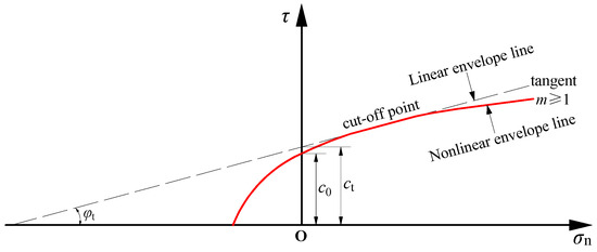
Figure 1.
The schematic diagram of the nonlinear Mohr–Coulomb failure criterion.
When m ≠ 1, differentiate σn:
Simplified:
Assuming that the tangent point coordinates (σn0, τ0), the tangent equation is as follows:
where τ0 = c0 (1 + σn0/σt)1/m.
Substitute the derivative into the tangent equation:
Simplified:
Further simplification yields the tangent Equation of (7) as follows:
where ct is the intercept of the tangent Equation (8); tanφt is the slope of the tangent Equation (8), which can be obtained using the slope formula.
Combining (7), (8), and (9) yields the following:
Using strength reduction technology [28], the slope safety factor Fs is incorporated to bring it to a critical limit equilibrium state [29]. After strength reduction, the strength index of the rock and soil material is as follows:
2.3. Dynamic Stability Pseudo-Static Analysis Method
Currently, the pseudo-static method is a commonly used simplified research method for seismic loads. This method decomposes seismic forces into two static forces in the horizontal and vertical directions, represented by khW and kvW. W is the weight of the sliding soil, while the horizontal dynamic influence equivalent static force and the numerical dynamic influence equivalent static force act on a rigid body particle, represented by coefficients kh and kv, respectively, as shown in Equation (12):
where kh is the horizontal seismic acceleration coefficient, kv is the vertical seismic acceleration coefficient, and λ is the seismic effect ratio coefficient of kv relative to kh.
kv = λkh
3. Derivation of the Safety Factor for Slopes Under the Combined Support of Anti-Slip Piles and Reinforced Soil
3.1. Destruction Mode
The research findings of Chen [26], Donald [30], and Dawson et al. [31] have shown that the shape of the failure surface of a simple homogeneous slope is similar to a logarithmic spiral. Hence, this paper considers the failure surface of a slope under the combined support of anti-slip piles and reinforced soil to adopt a logarithmic spiral rotation mechanism passing through the toe of the slope as the upper limit analysis model for slope stability, as shown in Figure 2.
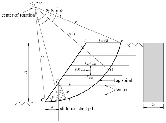
Figure 2.
The schematic diagram of the upper limit analysis of slope stability under the action of combined anti-slip piles and reinforced soil support.
Angular parameters such as β, θ0, θ, and θh, and length parameters such as L, r0, r(θ), and rh are all variable parameters related to the slope failure mode. ω represents the rotational angular velocity. The logarithmic spiral equation [24] is as follows:
where r is the polar radius associated with θ; θ0 is the angular parameter of the spiral rotation mechanism; r0 is the polar radius when θ = θ0; φt is the internal friction angle of the soil.
Based on the geometric relationship of the spiral line failure surface, the equations for r0, H, and L are established as follows:
To facilitate slope stability analysis, the layered reinforcement is assumed to form a uniform continuous model (as shown in Figure 2), where k0 represents the average tensile strength of the reinforcement within the slope. Bending effects are neglected, and the reinforcement is subjected solely to tensile stress. The reinforcement density kt is the tensile strength of the reinforcement per unit thickness within the slope, expressed by the following equation [32]:
where T is the tensile strength of the reinforcing materials per unit width; s is the vertical spacing of the reinforcing materials. In the uniformly distributed reinforcing material model, s = H/n, where n is the number of reinforcing material layers.
For the uniform reinforcement pattern:
where H is the slope height (m); L is the length of AB (m); β is the slope angle (°).
3.2. Energy Consumption Calculation
Energy consumption analysis consists of two parts: external work and internal energy loss. External work includes gravitational work and quasi-static seismic effect work, while internal energy loss includes energy loss at the soil interface, energy loss within the reinforcement, and work performed by the anti-sliding pile resistance.
3.2.1. Gravitational Work
Assuming that the power achieved by gravity in the OBC, OBA, and OAC zones is W1, W2, and W3, the power achieved by gravity in the ABC zone is Wsoil:
where γ is the unit weight of rock and soil (kN/m3); r0 is the length of OB; ω is the angular velocity of rotation; and the functional expressions of f1, f2, and f3 related to θ0, θh, and φ [29] are as follows:
3.2.2. Static Seismic Effect Work
(1) The horizontal seismic force work power is as follows:
(2) The vertical seismic force work power is the following:
where functions f4, f5, and f6 are functions related to θh, θ0, φ, and β, and their expressions [33] are as follows:
3.2.3. Internal Energy Loss Power
(1) The energy dissipation power on the soil cross-section is the following:
(2) The energy dissipation power on the reinforcement is as follows:
where functions f8, f9, and f10 are functions related to θh, θ0, and φ, and their expressions [24] are as follows:
3.2.4. Anti-Slip Piles Resistance Work
The distribution of effective soil pressure on the side of the pile plays a crucial role in the design of anti-slide piles. This paper follows the recommendations of scholars such as Liu X.Y. [34] and Han M. [35], adopting a distribution pattern where the effective soil pressure on the side of the pile is parallel to the tangent direction of the slip plane. Assume that F represents the effective anti-slide force on the side of the anti-slide piles, and a denotes the horizontal distance between the anti-slide piles and the toe of the slope. The intersection points of the anti-slide piles with the slope surface and the failure slip plane are denoted as F and E, respectively. The angle corresponding to point E in polar coordinates is θE, and the length between points F and E represents the pile length h of the anti-slide piles within the failure plane. The anti-slide piles are located on the slope surface, and based on geometric relationships, the following can be derived:
Since xF = xE, in the polar coordinate system:
Accordingly, from Equations (34) and (36), it can be seen that θE can be expressed in terms of θ0, φt, β, H, a, L, and r0:
For the case where the effective soil pressure on the pile side is parallel to the tangent direction of the slip plane, the external work performed by the effective anti-slip force F provided by the anti-slip piles and the corresponding bending moment M is given by the following [36]:
where mE is an empirical coefficient depending on the distribution pattern of the effective soil pressure on the pile side. This paper adopts a linear triangular distribution model, with mE = 1/3 selected in reference [37].
3.3. Slope Stability Coefficient
According to the principle of conservation of internal and external energy, the power exerted by external loads is equal to the internal dissipation power. The shear strength parameters φt and ct of the soil are calculated using Equation (11) to determine the strength reduction, and the critical stability height is set equal to the original slope height. The safety factor calculation formula for the reinforced-soil slope is as follows:
From Equation (11), φf is a function of Fs, and the internal friction angle φ in Equation (39) is φf = arctan(tanφ/Fs); then, the functional expression of the safety factor Fs is actually an implicit function with respect to the unknown quantities θh, θ0, φf, and β. As a result, Fs can be treated as the objective function, and Equation (39) can be optimized and iterated using MATLAB R2022a software to ultimately obtain the optimal upper bound solution for the safety factor Fs.
4. Comparison of Calculation Examples
4.1. Comparison of Slope Safety Factors Under Proposed Static Seismic Effects
Based on the strength reduction method, this paper compares and analyzes the slope safety factor Fs calculated using the energy dissipation method with the results obtained by Deng D.P. et al. [38] using the limit equilibrium method. The comparison results are shown in Table 1. The error between the results of this paper and those in [38] is no more than 3.20%, which verifies the accuracy of the calculation method used in this paper.

Table 1.
Comparison of slope safety factors Fs under seismic loading effects.
4.2. Comparison of Critical Heights of Reinforced Earth Slopes
The results of this study were compared with the critical height Hcr of uniformly reinforced-soil slopes calculated by Cui X.Z. et al. [39]. The research method used in this study fully considered the energy loss rate when the reinforcement and soil are bonded together. The comparison results are shown in Table 2. The results of this study differed from the critical height obtained in [39] by only 0.43% to 8.46%, verifying the correctness of the theoretical derivation and programming calculations in this study.
Table 2.
Comparison of critical heights of reinforced-soil slopes Hcr.
4.3. Comparison of Slope Safety Factors Under the Support of Anti-Slip Piles
The slope safety factors Fs calculated in this paper under the support of anti-slip piles were compared and analyzed with the calculation results of Tan H.H. et al. [37] and Zeng Y.L. et al. [24]. The comparison results are shown in Table 3. The results show that the slope safety factor results in this paper differ from the calculated results in the existing literature by less than 5%, proving the reliability of the calculation method in this paper.
Table 3.
Comparison of slope safety factor Fs under the action of anti-slip-pile support.
4.4. Numerical Simulation Analysis of Safety Factor Comparison for Reinforced Earth Slopes
The safety factor Fs of the reinforced-soil slope obtained through numerical simulation analysis in this paper was compared with the numerical simulation results of Zeng Y.L. et al. [24]. The results are shown in Table 4. The results show that the slope safety factor results in this paper are close to the simulation results in the existing literature, which proves the reliability of the numerical simulation method.
Table 4.
Comparison of the safety factor of reinforced-soil slope under different working conditions.
5. Influencing Factor Parameters and Numerical Simulation Analysis
Soil parameters selected: slope height H = 13.5 m, slope angle β = 65°, soil unit weight γ = 18.5 kN/m3, cohesion c = 20 kPa, and internal friction angle φ = 25°.
Fan F.F. et al. [40] conducted a theoretical study on the stability analysis of three-dimensional anti-slide piles and reinforced slopes under seismic loads, focusing on horizontal seismic acceleration kh = 0.0–0.3 and proportional coefficient λ = −1.0–1.0; Li L.H. et al. [41] conducted model tests with reinforcing material tensile strength T = 1–45 kN/m and reinforcing material layers n = 0–6, verifying that reinforced soil has a significant stabilizing effect on slopes; Zhang F. et al. [42] selected reinforcement tensile strength T = 0–100 kN/m and analyzed the influence of three reinforcement lengths on the mechanical properties of reinforced-soil-retaining walls, indicating that reinforcement length has a significant impact on the maximum internal force of the reinforcement; Gu J. et al. [43] conducted numerical simulations to investigate the influence of geogrid length l = 6–9 m on slope safety factors, concluding that safety factors increase with length; Tan H.H. et al. [37] assumed an effective anti-slip force F = 500 kN/m on the side of the anti-slip piles and studied the impact of single pile positions ranging from 0 m to 26 m on slope stability. They found that as the anti-slip piles moved from the toe of the slope toward the slope crest, the safety factor first decreased and then increased; Zeng Y.L. et al. [24] set the length of the anti-slide piles to 12 m and analyzed the stability of slopes reinforced by a combination of anti-slide piles and geogrids. Based on the above research findings and combined with engineering requirements, this paper’s parameter analysis further expanded the range of key parameter values, with specific values shown in Table 5.
Table 5.
Value range of parameter analysis.
Horizontal seismic acceleration kh is taken as 0.1, 0.2, and 0.3, and the proportional coefficient λ is taken as 0.5. The stability of the slope under different conditions is analyzed under the combined support of anti-slide piles and reinforced soil.
5.1. Analysis of the Stability of Reinforced-Soil Slopes Under Seismic Effects
When considering seismic effects, the horizontal seismic acceleration coefficient kh = 0–0.3, and the proportional coefficient λ = 0.5. When the number of reinforcement layers n = 4 and the tensile strength of the reinforcement T = 50–90 kN/m, the safety factor of the reinforced-soil slope varies with different tensile strengths, as shown in Figure 3; when the tensile strength of the reinforcement T = 70 kN/m, and the number of reinforcement layers n = 3–7, the variation curve of the safety factor of the reinforced-soil slope under different reinforcement layer numbers is shown in Figure 4.
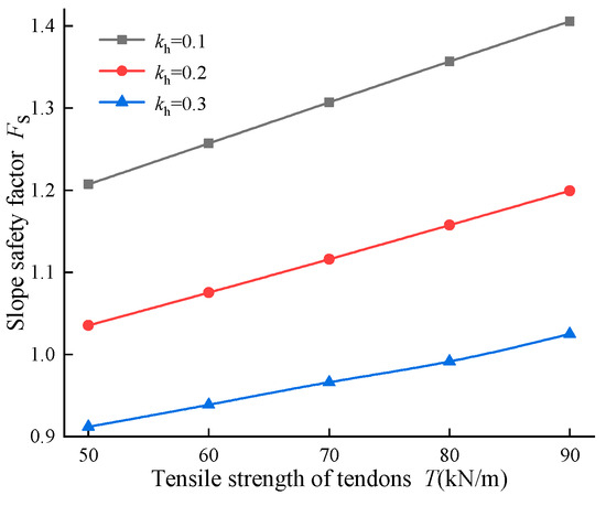
Figure 3.
The influence of tensile strength of reinforcement on the slope safety factor.
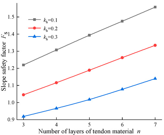
Figure 4.
The influence of reinforcement layers on the slope safety factor.
It can be seen from Figure 3 and Figure 4 that when kh increases from 0.1 to 0.3, the maximum reductions in the slope safety factor due to the tensile strength of the reinforcing material and the number of reinforcing layers are 27.06% and 26.81%, respectively. This suggests that as the horizontal seismic acceleration increases, the safety factor of the reinforced-soil slope decreases significantly, making it highly prone to instability. When kh = 0.1, increasing T from 50 kN/m to 90 kN/m and increasing n from three to seven layers results in respective increases in the safety factor of the reinforced-soil slope of 16.42% and 27.69%. This implies that as the tensile strength and number of layers of the reinforcing material increase, the stability of the slope is significantly improved; nevertheless, as kh increases, the maximum improvement in the safety factor of the reinforced-soil slope decreases from 16.42% to 12.39% and from 27.69% to 24.07%, respectively, indicating that the greater the seismic effect, the more significant the adverse impact on the stability of the reinforced-soil slope. Therefore, strong seismic effects significantly weaken the reinforcement effect of geotextiles, leading to a substantial decrease in the stability of reinforced-soil slopes and an increased likelihood of instability and failure. Seismic effects are an indispensable factor in actual engineering projects, and in regions prone to strong earthquakes, it is necessary to reasonably increase reinforcement parameters to ensure slope stability.
Setting kh = 0.1, λ = 0.5, reinforcement layer number n = 3–6, and reinforcement tensile strength T = 50–90 kN/m, the safety factor variation curves for reinforced-soil slopes under different tensile strengths and reinforcement layer numbers are shown in Figure 5.
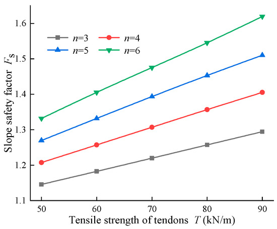
Figure 5.
The influence of tensile strength and the number of reinforcement layers on the slope safety factor.
As illustrated in Figure 5, the safety factor of reinforced-soil slopes increases significantly with higher tensile strength of the reinforcement and an increasing number of reinforcement layers. When T = 50 kN/m, increasing the n value from 3 to 6 only improves the safety factor of the reinforced-soil slope by 16.24%; nonetheless, when T = 90 kN/m, increasing n from 3 to 5 improves the safety factor by 16.66%, and increasing it to 6 further improves the safety factor by 25.10%. This demonstrates that enhancing the tensile strength of the reinforcing materials is more effective than increasing the number of reinforcing layers in improving slope stability. In consequence, in actual engineering projects, prioritizing the enhancement of the tensile strength of reinforcing materials is recommended to improve the slope stability.
5.2. Analysis of Slope Stability Under the Support of Anti-Slip Piles
For steep slopes, employing a single-reinforcement measure under seismic effects significantly affects stability, so anti-slide piles are added at the slope toe to enhance the slope safety factor.
When the horizontal distance between anti-slide piles and the slope toe a = 1.5 m, and the effective anti-slide force on the anti-slide piles F = 200–400 kN/m, and the pile length h = 3–11 m, the variation curves of the slope safety factor under different effective anti-slip forces and pile lengths are shown in Figure 6; when the pile length h = 5 m and the horizontal distance between anti-slide piles and the slope toe a = 1–3 m, the variation curves of the slope safety factor under different horizontal distances from the toe of the slope and different effective anti-slip forces of the anti-slip piles are shown in Figure 7. The effective anti-slide force on the anti-slide piles F = 250 kN/m, and the variation curves of the slope safety factor under different horizontal distances from the toe of the slope and different pile lengths are shown in Figure 8.
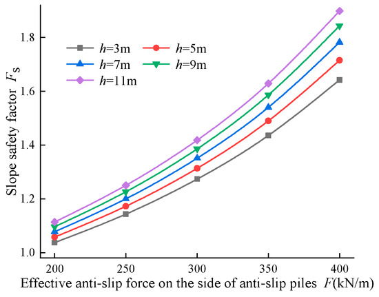
Figure 6.
The influence of effective slip resistance and pile length of slip-resistant piles on the slope safety factor.
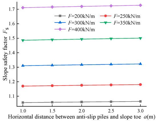
Figure 7.
The influence of horizontal distance from the toe and effective slip resistance of anti-slip piles on the slope safety factor.
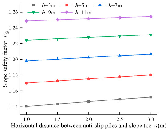
Figure 8.
The influence of horizontal distance from the slope toe and pile length on the slope safety factor.
As depicted in Figure 6, as the effective anti-slip force of the anti-slip piles increases and the pile length grows, the slope safety factor significantly improves, and stability is markedly enhanced. When the effective anti-slip force F of the anti-slip piles is 200 kN/m and 400 kN/m, respectively, and the pile length h increases from 3 m to 11 m, the slope safety factor increases by 7.38% and 15.6%, respectively, indicating that increasing the pile length is beneficial for improving the slope safety factor; when the pile length h of the anti-slip piles is 3 m and 11 m, respectively, the effective anti-slip force F increases from 200 kN/m to 400 kN/m, resulting in increases in the slope safety factor of 58.30% and 70.41%, respectively. This reveals that increasing the effective anti-slip force of the anti-slip piles significantly enhances slope stability, and the longer the pile length, the greater the increase in the slope safety factor and the more pronounced the reinforcement effect. Thus, in actual construction, if the slope is generally stable but has a low safety factor, longer piles can be used to appropriately increase the slope safety factor; conversely, for slopes with poor stability, anti-slip piles with a larger effective anti-slip force can be used to reinforce the slope and significantly enhance slope stability.
As depicted in Figure 7 and Figure 8, increasing the horizontal distance between the anti-slip piles and the toe of the slope improves the slope safety factor and enhances slope stability. Increasing the horizontal distance a from the anti-slide piles to the slope toe from 1.0 m to 3.0 m resulted in safety factor increases of 0.76% and 0.99% for pile forces F of 200 kN/m and 400 kN/m, respectively. These results demonstrate that enlarging the horizontal distance a enhances the overall slope stability. Furthermore, the magnitude of the safety factor improvement associated with increasing a was greater for the higher pile force (F = 400 kN/m) than for the lower value (F = 200 kN/m). Conversely, for pile lengths h of 3 m and 11 m, the corresponding safety factor increases were 1.03% and 0.44%. This reveals that the enhancement in safety factor achieved by increasing a is more pronounced for shorter pile lengths (h = 3 m) compared to longer ones (h = 11 m). When the horizontal distance between the anti-slip piles and the slope toe is a constant value, the slope safety factor significantly increases with the increase in effective anti-slip force. For example, when a = 2.0 m, and F increases from 200 kN/m to 400 kN/m, the slope safety factor increases by 62.18%, and the increase is most pronounced when F = 350–400 kN/m, with the safety factor reaching a maximum percentage increase of 15.12%. However, the increase in the slope safety factor slightly decreases with the increase in pile length. For example, when a = 1.0 m, h = 3–5 m, and h = 9–11 m, the slope safety factor decreases from an increase of 2.59% to an increase of 2%. Hence, when using anti-slide piles to reinforce slopes, the arrangement of the anti-slide piles also has a significant impact on slope stability. The optimal reinforcement position should be arranged in the middle to lower part of the slope.
5.3. Numerical Simulation Analysis of Slope Stability Under the Combined Support of Anti-Slip Piles and Reinforced Soil
To further investigate the stability of slopes under the combined support of anti-slip piles and reinforced soil, finite element numerical simulation software Optum G2 2023 was used to conduct a simulation analysis of steep embankment slopes.
The soil parameters selected are as follows: slope height H = 13.5 m, slope angle β = 65°, soil weight γ = 18.5 kN/m3, cohesion c = 20 kPa, and internal friction angle φ = 25°. The material parameters of the model are shown in Table 6. Through references [33], the horizontal seismic acceleration kh is taken as 0.1, and the proportional coefficient λ is taken as 0.5. The quasi-static seismic effects are simulated using fixed body loads, with units in acceleration (shown by the arrows in Figure 9). According to relevant studies [20,23,44], the slope is modeled using the Mohr–Coulomb material type, and the boundary conditions are selected as standard boundary conditions; that is, the left and right sides of the model are constrained by lateral displacement, and the bottom is constrained by both lateral and normal displacement. A uniformly distributed reinforcement grid is used within the slope, with a tensile strength of 70 kN/m, laid in layers at 1 m intervals, and a grid thickness of 5 mm.
Table 6.
Model material parameters.
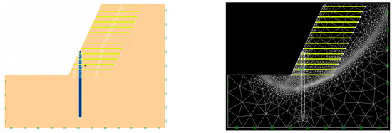
Figure 9.
Anti-slide piles and geogrid combined support slope layout and grid division diagram.
During model establishment, the strength reduction limit analysis method was used to determine the safety factor of the slope. The model adopted long-term time conditions, with 3000 and 5000 units, and set adaptive meshing and three iterations. The initial number of units was 1000, and the adaptive control variable was shear dissipation. The numerical model of the combined anti-slide piles and geogrid slope support system is shown in Figure 9.
The length of geogrids is one of the key parameters affecting the stability of reinforced-soil slopes. To investigate the relationship between the length of geogrids and the location of slope failure slip surfaces, four scenarios were set up, corresponding to geogrid lengths l of 6, 8, 10, and 12 m. The shear dissipation cloud maps and safety factor comparisons of reinforced-soil slope failure modes under different working conditions are shown in Figure 10.
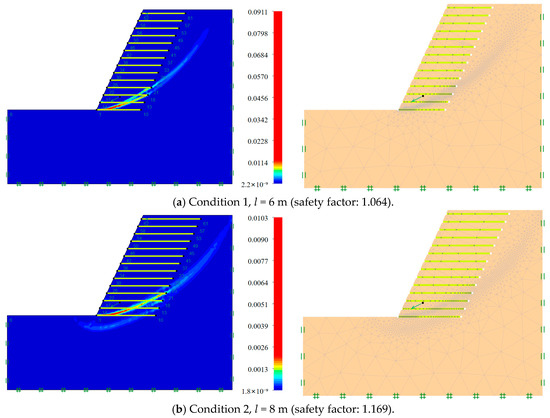
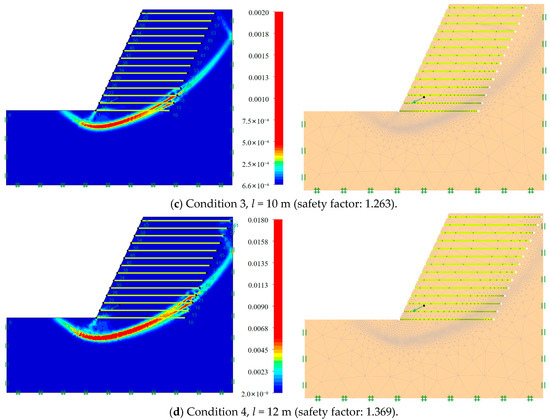
Figure 10.
Shear dissipation cloud diagram and grid division diagram of failure mode of reinforced-soil slope under different working conditions.
As presented in Figure 10, an increase in the length of the geogrid has a significant effect on the location of the slope failure slip plane. As the geogrid length increases from 6 m to 12 m, the failure surface of the slope progressively recedes backward, indicating that the confining and restraining effect of the geogrid on the slip surface strengthens with its increasing length.
As the length of the geogrid increases, the overall displacement of the slope shows a decreasing trend. In Conditions 1 and 2, the areas with larger displacements are primarily concentrated near the toe of the slope, and the range of slope face displacement is relatively large; whereas, in Conditions 3 and 4, the range of areas with larger displacements is significantly reduced, and the peak displacement values also decrease. This signifies that increasing the length of the geogrid effectively restricts the displacement of slope soil and enhances slope stability.
The safety factor of the slope also shows a gradual increase with the increase in the length of the geogrid; when the length of the geogrid is increased from 6 m to 12 m, the safety factor of the slope increases by 28.67%.
The improvement in slope safety factor is closely related to the rearward displacement of the slip plane, changes in the morphology of the slip plane, and a reduction in displacement. An increase in the length of the geogrid causes the slip plane to shift rearward, thereby reducing the downward torque on the soil at the slip plane. Furthermore, changes in the morphology of the slip plane (deepening) increase the contact area between the soil and the geogrid, resulting in stronger anti-slip force provided by the geogrid, thereby enhancing the slope’s anti-slip stability. Moreover, the reduction in displacement signifies that the deformation of the slope soil is restricted, further improving the overall stability of the slope. Hereby, the increase in geogrid length enhances the slope safety factor and stability through multiple mechanisms, including altering the position and morphology of the slip surface and restricting soil displacement.
As can be observed from Figure 10c,d, as the length of the geogrid approaches the right boundary of the numerical model, the slope failure mode exhibits upward reversal failure. Thus, the width of the model crest was altered to further investigate the influence of the model boundary on the numerical simulation analysis results, as shown in Figure 11.
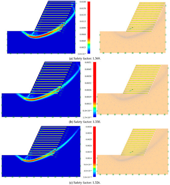
Figure 11.
Shear dissipation cloud diagram and grid division diagram of reinforced-soil slope failure mode under different slope top widths.
As can be seen in Figure 11, the potential slip plane morphology of the slope changes significantly with an increase in the crest width. Figure 11a depicts the slip plane exhibits an upward curvature near the right boundary of the model; while in Figure 11b,c, as the crest width increases, the failure surface gradually normalizes, the curvature disappears, and the failure surface becomes deeper and smoother, conforming to the typical logarithmic spiral shape. This denotes that the model boundary significantly influences the development of the failure surface, and increasing the crest width helps reduce boundary constraint effects; In addition, the safety factor of the slope is significantly affected by the width of the slope top. As the anti-bending phenomenon of the sliding surface weakens, the safety factor gradually decreases, indicating that a reasonable model size is crucial for obtaining reliable numerical simulation results.
The above analysis shows that for steep embankment slopes, using a single geogrid for support results in relatively low stability. For that reason, anti-slip piles are added within the slope body to enhance the slope safety factor. Four different conditions were set up. Conditions 5 and 6 correspond to the horizontal distance a between the anti-slip piles and the toe of the slope, being 2, 4, and 6 m, respectively, with all piles having a length of 12 m. Condition 8 corresponds to a being 6 m, with a pile length of 13 m. The shear dissipation cloud diagram and safety factor comparison of the failure mode of the combined support slope of anti-slip piles and geogrids under different working conditions are shown in Figure 12.
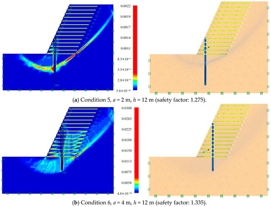
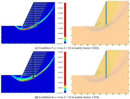
Figure 12.
Shear dissipation cloud diagram and grid division diagram of slope failure modes under different working conditions for anti-slip piles and geogrids combined support.
As indicated in Figure 12, compared to single geogrid support, the combined use of anti-slip piles and geogrids for slope support demonstrates significant advantages. Compared to Condition 2, which does not include anti-slip piles, the slope safety factors for Conditions 5–7 increased by 9.07%, 14.20%, and 4.53%, respectively. Meanwhile, when the anti-slip pile is positioned at the lower part of the slope (Condition 5) and the middle part (Condition 6), the safety factors are relatively high, especially when positioned in the middle, where the safety factor reaches its maximum value of 1.335. Nevertheless, when positioned at the upper part of the slope (Condition 7), the safety factor decreases, but by extending the pile length (Condition 8), the safety factor increases again. This establishes that the positioning and length of anti-slide piles are two interrelated factors. By reasonably positioning the piles and combining them with appropriate pile lengths, the slope safety factor can be maximized.
As indicated in Figure 12a–c, when the anti-slide pile is arranged at the lower part of the slope, the slip surface is obstructed near the piles, but there is still a large sliding area extending toward the middle of the slope; as the anti-slide pile is moved upward to the middle of the slope, the obstruction effect of the piles on the slip surface becomes more pronounced, and the range further decreases. When the pile is arranged in the upper part of the slope, the blocking effect of the sliding surface at the pile is relatively weakened, and there is a tendency to develop deeper into the slope. This establishes that the closer the anti-slide pile is positioned to the middle and lower sections of the slope, the more pronounced the blocking effect on the upper part of the slip surface, effectively limiting its upward development; when positioned at the upper section, the reinforcement effect of the anti-slide pile is relatively weakened. This also confirms that the optimal reinforcement position for anti-slide piles should be in the middle and lower sections of the slope.
Operating Conditions 7 and 8 represent whether the end of the anti-slip piles extends beyond the bottom layer of the geogrid. As shown in Figure 12c,d, increasing the pile length enhances the anti-slip pile’s ability to block the slip surface, making it difficult for the slip surface to continue developing toward the rear of the pile. The range of the slip surface further contracts near the pile. This indicates that increasing the pile length allows the anti-slip piles to penetrate deeper into the soil, enabling them to more effectively perform their anti-slip function, providing the slope with stronger anti-slip torque, and delaying the progression of slope failure.
6. Conclusions
- (1)
- Seismic effects have a significant adverse impact on slope stability. As the horizontal seismic acceleration kh increases, the slope safety factor Fs gradually decreases. When conducting slope stability assessments, horizontal seismic effects are an important factor that cannot be ignored. In areas prone to strong earthquakes, appropriate reinforcement measures should be considered to ensure slope stability. Additionally, compared to single anti-slide piles or geogrid support, the combined use of anti-slide piles and geogrids demonstrates a remarkable advantage in enhancing slope stability.
- (2)
- As the tensile strength T of the reinforcing materials and the number of layers n increase, the safety factor Fs of the reinforced-soil slope obviously improves. Enhancing the tensile strength of the reinforcing materials is more effective than increasing the number of layers in improving slope stability. In actual engineering projects, prioritizing the enhancement of the tensile strength of the reinforcing materials is recommended to improve the slope stability. Increasing the geosynthetic length by l produces quantifiable improvements in the safety factor Fs of reinforced slopes. A progressive extension of l reduces overall slope displacement magnitude, lowers displacement peaks, and induces backward recession of the failure surface. These collective mechanisms enhance the slope stability.
- (3)
- As the effective anti-slip force F and pile length h of the anti-slip piles increase, the slope safety factor Fs remarkably improves. Furthermore, the longer h is, the greater the increase in the slope safety factor due to F, and the more significant the reinforcement effect. In actual construction, when the slope safety factor is low but the slope is relatively stable, longer piles can be used to moderately increase the slope safety factor. Conversely, when the slope stability is poor, anti-slide piles with higher effective anti-slide force can be employed to reinforce the slope, thereby greatly enhancing slope stability.
- (4)
- Increasing the horizontal distance a between the anti-slip piles and the toe of the slope improves slope stability. The larger the value of F and the smaller the value of h, the greater the increase in the slope safety factor Fs when increasing the value of a. When a is a constant value, the slope safety factor increases significantly with an increase in F, particularly during the stage where F = 350–400 kN/m. However, the rate of increase in the slope safety factor decreases slightly as h increases. In actual engineering applications, the optimal reinforcement position for anti-slide piles should be located in the middle to lower part of the slope body.
- (5)
- The current article’s study of the upper limit analysis of the stability of steep slopes supported by anti-slip piles and reinforced soil is limited to homogeneous, idealized slopes. The next step of the research will focus on complex soil layers or geological conditions, extending the analysis to the stability of slopes under hydraulic coupling effects and non-homogeneous soil conditions, and exploring in-depth research in combination with actual engineering cases.
Author Contributions
Conceptualization, W.L.; Methodology, W.L. and G.X.; Software, G.X.; Validation, W.L. and G.X.; Formal analysis, G.X. and Z.T.; Investigation, Z.G. and H.W.; Resources, W.L. and J.C.; Data curation, J.C., Z.G. and H.W.; Writing—original draft, G.X.; Writing—review & editing, W.L. and Z.T.; Visualization, Z.T.; Supervision, W.L., Z.T. and J.C.; Project administration, W.L., G.X. and J.C.; Funding acquisition, W.L. and J.C. All authors have read and agreed to the published version of the manuscript.
Funding
Project (52268063) supported by the National Natural Science Foundation of China; Project (52108320) supported by the National Natural Science Foundation of China Youth; Project (20224BAB204063) supported by the Natural Science Foundation of Jiangxi Province; Project (YC2024-S393) supported by Special Funding Program for Graduate Student Innovation in Jiangxi Province.
Data Availability Statement
The original contributions presented in this study are included in the article. Further inquiries can be directed to the corresponding author.
Conflicts of Interest
Author Zhi Tao was employed by the company Hefei Housing Construction Apartment Section, China Railway Shanghai Group Co., Ltd. The remaining authors declare that the research was conducted in the absence of any commercial or financial relationships that could be construed as a potential conflict of interest.
References
- Li, S.L.; Qiu, C.; Huang, J.K.; Guo, X.P.; Hu, Y.C.; Mugahed, A.-S.Q.; Tan, J. Stability analysis of a high-steep dump slope under different rainfall conditions. Sustainability 2022, 14, 11148. [Google Scholar] [CrossRef]
- Ji, Z.M.; Chen, T.L.; Wu, F.Q.; Li, Z.H.; Niu, Q.H.; Wang, K.Y. Assessment and prevention on the potential rockfall hazard of high-steep rock slope: A case study of Zhongyuntai mountain in Lianyungang, China. Nat. Hazards 2023, 115, 2117–2139. [Google Scholar] [CrossRef]
- Zhang, F.; Qian, Z.H.; Jia, S.L.; Su, X. Stability analysis of locally reinforced cut-fill embankment in mountainous area. J. Hohai Univ. Nat. Sci. 2025, 1–10. Available online: http://kns.cnki.net/kcms/detail/32.1117.TV.20250527.1653.018.html (accessed on 15 July 2025).
- Santhosh Kumar, V.; Chandrasekaran, S.S. Impact Analysis of a Building Collapse Caused by a Rainfall-Induced Landslide in Kerala, India. Buildings 2022, 12, 1395. [Google Scholar] [CrossRef]
- Li, X.D.; Wang, P.; Wang, L.L.; Wang, H.J.; Chang, W.B.; Qian, Z.L. Influence of top building load on the slope stability under strong earthquakes. China Earthq. Eng. J. 2021, 43, 1220–1227. [Google Scholar]
- Luo, W.; Lv, X.; Xu, C.J.; Chen, J.Y.; Tao, Z. Nonlinear Energy Consumption Analysis of Cracked Slopes Stability Considering Hydraulic Effect. J. Chongqing Jiaotong Univ. Nat. Sci. 2024, 43, 26–34+53. [Google Scholar]
- Lin, Y.G.; Yang, C.S.; Xu, A.Y.; Ma, H.; Li, Y.D.; Wang, C.Z. Parameter Optimization Analysis of Buttressed Pile Foundation Beam Retaining Wall Under Seismic Action. Buildings 2025, 15, 1748. [Google Scholar] [CrossRef]
- Zhou, L.; Su, L.; Wang, Z.; Zhu, D.C.; Shi, W.; Ling, X.Z. Slope stability and effectiveness of treatment measures during earthquake. Sustainability 2023, 15, 5309. [Google Scholar] [CrossRef]
- Zucca, M.; Valente, M. On the limitations of decoupled approach for the seismic behaviour evaluation of shallow multi-propped underground structures embedded in granular soils. Eng. Struct. 2020, 211, 110497. [Google Scholar] [CrossRef]
- Yang, K.H.; Thuo, J.N.; Chen, J.W.; Liu, C.N. Failure investigation of a geosynthetic-reinforced soil slope subjected to rainfall. Geosynth. Int. 2019, 26, 42–65. [Google Scholar] [CrossRef]
- Zhang, C.Y.; Yin, Y.P.; Yan, H.; Zhu, S.N.; Li, B.; Hou, X.F.; Yang, Y.T. Centrifuge modeling of multi-row stabilizing piles reinforced reservoir landslide with different row spacings. Landslides 2023, 20, 559–577. [Google Scholar] [CrossRef]
- Yang, G.; Wu, Z.L.; Zhang, L.; Hou, J.F.; Tong, S.; Liu, F.; Zheng, Y. A Study on the Deformation Mechanism of a Landslide Reinforced with an Anti-Slip Pile Under the Effect of Reservoir Water Level Decline. Water 2025, 17, 1390. [Google Scholar] [CrossRef]
- Zhang, W.P.; Li, D.D.; Zeng, G.H.; Zhang, S.H.; Cui, M.X. Upper Bound Method for Reinforced Soil Slopes under Nonlinear Mohr-Coulomb Yield Condition. J. Yangtze River Sci. Res. Inst. 2020, 37, 108–114. [Google Scholar]
- Xu, P.; Zhong, Y.; Ma, H.D.; Chen, L.F.; Li, T.; Yang, G.Q.; Liang, X.M. Upper Bound Analysis of Bearing Capacity of Reinforced Soil Retaining Walls under Strip Footing Load. J. Railw. Eng. Soc. 2023, 40, 14–19. [Google Scholar]
- Gao, Y.C.; Zhao, Y.; Xu, T.Y.; Xu, J.L. Stability analysis of ultra-high and steep reinforced soil fills slopes based on strength reduction. Arch. Civ. Eng. 2024, 70, 417–430. [Google Scholar] [CrossRef]
- Wang, Z.; Sun, Z.B.; Yang, S.Y.; Nie, X.P.; Tan, X.H. Seismic stability analysis of three-dimensional reinforced slope based on pseudo-dynamic method. J. Hefei Univ. Technol. Nat. Sci. 2024, 47, 1288–1296. [Google Scholar]
- Deng, W.T.; Ding, X.M.; Yang, C.W.; Ou, Q.; Wang, C.Y.; Cao, G.W.; Xin, Y.W. Seismic response of high-filled reinforced embankment supported by pile and slab structure on slope terrain. Transp. Geotech. 2025, 50, 101475. [Google Scholar] [CrossRef]
- Fan, K.W.; Zou, W.L.; Zhang, P.; Wang, X.Q.; Shen, Y. Laboratory investigation and theoretical analysis of lateral pressure exerted by expansive soils on retaining walls with expanded polystyrene geofoam block upon water infiltration. Geotext. Geomembr. 2024, 52, 332–341. [Google Scholar] [CrossRef]
- Fan, K.W.; Shen, Y.; Han, Z.; Zou, W.L.; Liu, S.H.; Chen, Y.P.H. Impact of incorporating waste tire rubber particles into granular inclusion on reducing lateral swelling pressures of expansive soil against concrete retaining walls. Constr. Build. Mater. 2024, 457, 139462. [Google Scholar] [CrossRef]
- Cao, W.Z.; Zheng, J.J.; Xue, P.P. Development of combined retaining structure composed of anti-slide pile and reinforced earth retaining wall. J. Cent. South Univ. Sci. Technol. 2019, 50, 118–129. [Google Scholar]
- Ma, N.; Wu, H.G.; Ma, H.M.; Wu, X.Y.; Wang, G.H. Examining dynamic soil pressures and the effectiveness of different pile structures inside reinforced slopes using shaking table tests. Soil Dyn. Earthq. Eng. 2019, 116, 293–303. [Google Scholar] [CrossRef]
- Huang, Y.; Xu, X.; Mao, W. Numerical performance assessment of slope reinforcement using a pile-anchor structure under seismic loading. Soil Dyn. Earthq. Eng. 2020, 129, 105963. [Google Scholar] [CrossRef]
- Ren, Y.; Li, T.B.; Yang, L.; Wei, D.Q.; Tang, J.L. Stability analysis of ultra-high-steep reinforced soil-filled slopes based on centrifugal model tests and numerical calculation. Chin. J. Geotech. Eng. 2022, 44, 836–844. [Google Scholar]
- Zeng, Y.L.; Jin, B.; Wang, Q.S.; Guo, W.Q.; Chen, S.Q. Stability analysis of slope reinforced by anti-slide pile-reinforced soil based on limit theory. J. Railw. Sci. Eng. 2023, 20, 3362–3372. [Google Scholar]
- Wang, P.Y.; Lv, R.T.; Miao, J.W.; Zhang, C.L. Dynamic Response Characteristics and Damage Identification of Pile Body of Gravel Soil Slope Strengthened by Anti-slide Pile in Strong Earthquake Area: Take Jiuzhaigou Double-line Bridge of Sichuan-Qing Railway as an Example. Sci. Technol. Eng. 2024, 24, 10910–10920. [Google Scholar]
- Chen, W.F. Limit Analysis and Soil Plasticity; Elsevier: Amsterdam, The Netherlands, 1975. [Google Scholar]
- Luo, W.; Lv, X.; Xu, C.J.; Chen, J.Y.; Tao, Z.; Jiang, Z.Y. Nonlinear energy consumption analysis of multi-stage slope stability subjected to seismic effect and surcharge. Sci. Sin. Technol. 2024, 54, 1625–1636. [Google Scholar] [CrossRef]
- Lyness, J.F.; Owen, D.R.J.; Zienkiewicz, O.C. The finite element analysis of engineering systems governed by a non-linear quasi-harmonic equation. Comput. Struct. 1975, 5, 65–79. [Google Scholar] [CrossRef]
- Chen, Z.Y. Limit Analysis for the Classic Problems of Soil Mechanics. Chin. J. Geotech. Eng. 2002, 24, 1–11. [Google Scholar]
- Donald, I.B.; Chen, Z. Slope stability analysis by the upper bound approach fundamentals and methods. Can. Geotech. J. 1997, 34, 853–862. [Google Scholar] [CrossRef]
- Dawson, E.M.; Roth, W.H.; Drescher, A. Slope stability analysis by strength reduction. Geotechnique 1999, 49, 835–840. [Google Scholar] [CrossRef]
- Shi, T.F.; Zhao, L.H. Upper-bound stability limit analysis of reinforcement slope based on strengh reduction technique. J. Railw. Sci. Eng. 2011, 8, 40–46. [Google Scholar]
- Luo, W.; Liu, S.R.; Xu, C.J.; Chen, J.Y.; Lv, X. Upper-bound Limit Analysis of Seismic Quasi-static Stability of Multi-stage Slopes. Technol. Earthq. Disaster Prev. 2024, 19, 810–820. [Google Scholar]
- Liu, X.Y.; Cai, G.J.; Liu, L.L.; Zhou, Z.J. Investigation of internal force of anti-slide pile on landslides considering the actual distribution of soil resistance acting on anti-slide piles. Nat. Hazards 2020, 102, 1369–1392. [Google Scholar] [CrossRef]
- Han, M.; Li, Z.; Jia, J.Q.; Zhu, Z.G.; Liu, L.L. Estimation of internal force of stabilizing piles on landslides considering nonlinear landslide thrust and soil resistance. Bull. Eng. Geol. Environ. 2023, 82, 285. [Google Scholar] [CrossRef]
- Deng, B.; Xiao, Y.Q.; Yang, M.H.; Wang, D.X. Upper limit analysis of the stability of soil slopes reinforced by anti-slide piles under the fluctuation of groundwater level. J. Harbin Eng. Univ. 2025, 46, 710–719. [Google Scholar]
- Tan, H.H.; Zhao, L.H.; Li, L.; Luo, Q. Energy analysis method for pre-reinforcing slopes with anti-slide piles. Rock Soil Mech. 2011, 32 (Suppl. 2), 190–197. [Google Scholar]
- Deng, D.P.; Li, L.; Zhao, L.H. Research on quasi-static method of slope stability analysis during earthquake. J. Cent. South Univ. Sci. Technol. 2014, 45, 3578–3588. [Google Scholar]
- Cui, X.Z.; Tao, Z.Y.; Shang, Q.S.; Feng, H.B. Limit Analysis of Critical Heights of Reinforced Soil Slope. China J. Highw. Transp. 2007, 20, 1–6. [Google Scholar]
- Fan, F.F.; Li, J.; Ye, M.; Zhang, F. Three Dimensional Seismic Stability of Earth Slopes Reinforced with Piles. J. Disaster Prev. Mitig. Eng. 2021, 41, 394–402. [Google Scholar]
- Li, L.H.; Cao, Y.; Liu, J.Q.; Xiao, H.L.; Zhang, D.F.; Liu, Y.M. Experimental Study on Load Bearing Performance of Stone Columns under Different Reinforcement Methods. Chin. J. Rock Mech. Eng. 2023, 42, 3085–3094. [Google Scholar]
- Zhang, F.; Wen, Y.P.; Chen, Y.B.; Jia, S.L. Analytical method to determine reinforcement loads ofgeosynthetic-reinforced retaining wall. J. Cent. South Univ. Sci. Technol. 2021, 52, 4238–4251. [Google Scholar]
- Gu, J.; Zhang, M.X. Stability analysis of reinforced slopes based onstrength reduction theory. J. Shanghai Univ. Nat. Sci. 2019, 25, 990–1002. [Google Scholar]
- Peng, W.Z.; Zhao, M.H.; Xiao, Y.; Yang, C.W. Stability Analysis of Anti-slide Pile Reinforced Slope and Determination of Optimal Pile Position. J. Hunan Univ. Nat. Sci. 2020, 47, 23–30. [Google Scholar]


Disclaimer/Publisher’s Note: The statements, opinions and data contained in all publications are solely those of the individual author(s) and contributor(s) and not of MDPI and/or the editor(s). MDPI and/or the editor(s) disclaim responsibility for any injury to people or property resulting from any ideas, methods, instructions or products referred to in the content. |
© 2025 by the authors. Licensee MDPI, Basel, Switzerland. This article is an open access article distributed under the terms and conditions of the Creative Commons Attribution (CC BY) license (https://creativecommons.org/licenses/by/4.0/).