Article

Performance Limits of Hydraulic-Binder Stabilization for Dredged Sediments: Comparative Case Studies

1
Centre d’Etudes Génie Civil et Environnemental—CEGCE, 76530 Rouen, France
2
IMT Nord Europe, Centre for Materials and Processes, Université de Lille, LGCgE, 59500 Douai, France
3
Faculty of Engineering, Østfold University College, 1757 Halden, Norway
4
Department of Built Environment, OsloMet—Oslo Metropolitan University, 0130 Oslo, Norway
*
Author to whom correspondence should be addressed.
Buildings 2025, 15(14), 2484; https://doi.org/10.3390/buildings15142484
Submission received: 15 June 2025 / Revised: 5 July 2025 / Accepted: 8 July 2025 / Published: 15 July 2025
(This article belongs to the Collection Advanced Concrete Materials in Construction)

Abstract

Maintenance dredging produces large volumes of fine sediments that are commonly discarded, despite increasing pressure for beneficial reuse. Lime–cement stabilization offers one pathway, yet field performance is highly variable. This study juxtaposes two French marine dredged sediments—DS-F (low plasticity, organic matter (OM) ≈ 2 wt.%) and DS-M (high plasticity, OM ≈ 18 wt.%)—treated with practical hydraulic road binder (HRB) dosages. This is the first French study that directly contrasts two different DS types under identical HRB treatment and proposes practical boundary thresholds. Physical indexes (particle size, methylene-blue value, Atterberg limits, OM) were measured; mixtures were compacted (Modified Proctor) and tested for immediate bearing index (IBI). IBI, unconfined compressive strength, indirect tensile strength, and elastic modulus were determined. DS-F reached IBI ≈ 90–125%, UCS ≈ 4.7–5.9 MPa, and ITS ≈ 0.40–0.47 MPa with only 6–8 wt.% HRB, satisfying LCPC-SETRA class S2–S3 requirements for road subgrades. DS-M never exceeded IBI ≈ 8%, despite 3 wt.% lime + 6 wt.% cement. A decision matrix distilled from these cases and recent literature shows that successful stabilization requires MBV < 3 g/100 g, plastic index < 25%, OM < 7 wt.%, and fine particles < 35%. These thresholds permit rapid screening of dredged lots before costly treatment. Highlighting both positive and negative evidence clarifies the realistic performance envelope of soil–cement reuse and supports circular-economy management of DS.

1. Introduction

Dredged sediments (DS) are unavoidably generated from port and waterway maintenance, with hundreds of millions of cubic meters excavated annually worldwide [1,2,3]. Traditionally, these sediments have been disposed in confined facilities, landfills, or open water, but regulatory frameworks (e.g., the OSPAR Convention and EU Directives) now discourage open water dumping and encourage beneficial reuse [4,5,6]. Yet field pilots show that even high-organic matter (OM) clays can become subgrade once binder dose and dewatering are optimized [7,8,9]. There is growing interest in repurposing DS in civil engineering applications as a means of promoting sustainability and the circular economy. Reuse in infrastructure can conserve natural resources and reduce disposal costs [10,11,12,13,14].
However, raw DS often exhibit poor geotechnical properties that limit their direct use. They tend to have high water content (often above the liquid limit), significant fines, and low strength (e.g., undrained shear strength < 50 kPa). As a result, untreated DS usually fail to meet typical requirements for structural fill in roadway construction, such as liquid limit (LL) < 45, plasticity index (PI) < 20, minimum unconfined compressive strength > 0.25 MPa, or California Bearing Ratio (CBR) > 8. Soil stabilization is a well-established approach to improve these properties [15,16,17]. Traditional stabilizers like lime, cement, fly ash (FA), or other hydraulic binders can reduce moisture sensitivity and significantly increase the strength and bearing capacity of fine-grained soils and sediments [16,18,19]. Numerous studies have demonstrated that DS, when treated with cementitious binders, develop higher strength and stiffness, enabling their use in embankments and road layers. For example, it was proved that dredged silt stabilized with Portland cement and FA achieved substantial gains in unconfined compressive strength (UCS), CBR, and resilient modulus, making it suitable for pavement subbase [20]; the stabilized DS was also found to be more economical than conventional materials. Other researchers have reported similar improvements using various additives, including lime and even novel agents like enzymes or alkali activators [21,22,23].
Road construction relies heavily on quarried aggregates, yet DS—once dewatered and stabilized—can substitute a sizeable share of this non-renewable feedstock [24]. Pavements are built as a stack of four functional layers: (1) compacted subgrade, (2) subbase, (3) base (capping), and (4) surface courses (Figure 1). Most published work on dredged-material reuse targets the lower, high-volume layers where performance requirements are modest; here sediments can simply replace bulk fill after lime- or cement treatment. Far fewer studies tackle the base or surface courses, although recent research shows that processed DS can partially replace natural sand or fines in asphalt and binder mixes. For large-scale uptake, technical suitability must be matched by socio-economic viability—binder cost, local availability of DS, and regulatory acceptance ultimately govern whether sediments become a mainstream road material.
Road construction offers a promising outlet for reused DS, provided the material can be upgraded to meet technical standards. In France, the GTR (Guide Technique pour les Remblais et Couches de Forme) classification is used to assess soils for earthworks. Subgrade (platform) materials must have adequate bearing capacity and durability: e.g., an immediate bearing index (IBI or CBR% immediate) above 25–35%, depending on layer function, a UCS > 1 MPa to support construction traffic, and sufficient tensile strength and stiffness for long-term performance. Stabilization can enable clayey or silty DS to reach these criteria by inducing cementation reactions that bind particles and fill pores. Nevertheless, optimal binder content must be determined to balance performance with cost and potential environmental impacts (e.g., leaching of any contaminant).
This study tests the hypothesis that a low-plasticity, low-OM sediment can achieve LCPC-SETRA Class S2–S3 performance with ≤8 wt.% HRB (hydraulic road binder), whereas another high-plasticity, high-OM sediment will remain below roadworthiness thresholds even with combined lime–cement treatment.

2. Research Significance

The successful reuse of DS in road construction would have significant environmental and economic benefits. DS are often abundant local resources that currently pose disposal challenges. Valorizing these materials as construction soil can reduce the need for quarrying natural sand or gravel and minimize landfill volumes. This aligns with sustainable development goals by closing the loop in material flows (from waterway waste to useful fill) and lowering the carbon footprint associated with material transport and processing. This study therefore compares two contrasting DS under identical laboratory protocols. It investigates their recovery as a road platform material through binder stabilization. The DS studied, collected from maintenance dredging operations, were characterized and classified according to GTR to evaluate their baseline suitability. A series of laboratory tests were conducted on the raw and treated DS to (1) measure improvements in compaction behavior and IBI, and (2) determine the mechanical performance (compressive and tensile strength, modulus) of the stabilized material over time. The results are discussed considering French road material standards and compared with findings from the literature to assess the feasibility of using stabilized DS in road subgrades or foundation layers. This study also contributes to the knowledge base on soil stabilization, demonstrating that even challenging materials (high silt/clay content, moderate OM, salt content, etc.) can be engineered to meet technical specifications. Ultimately, this work supports a more sustainable dredging practice where DS are not merely disposed of, but are integrated into civil engineering works, fostering innovation in the recycling of geomaterials.

3. Materials and Methods

3.1. Dredged Sediments

The DS investigated (denoted DS-F) were marine DS sourced from the Dunkirk Port (Dunkirk, France). After collection, the wet DS were air-dried and then oven-dried at 40–50 °C to facilitate handling and testing. The dried bulk material was lightly crushed and passed through a 20 mm sieve to remove coarse debris (shells, pebbles, etc.), yielding fine-grained soil (Figure 2). A second batch, hereafter DS-M, was obtained from a low-energy harbor pocket. The wet sludge was vacuum-filtered until self-supporting, then oven-dried at 40 °C, ground < 20 mm, and stored in airtight drums prior to testing.
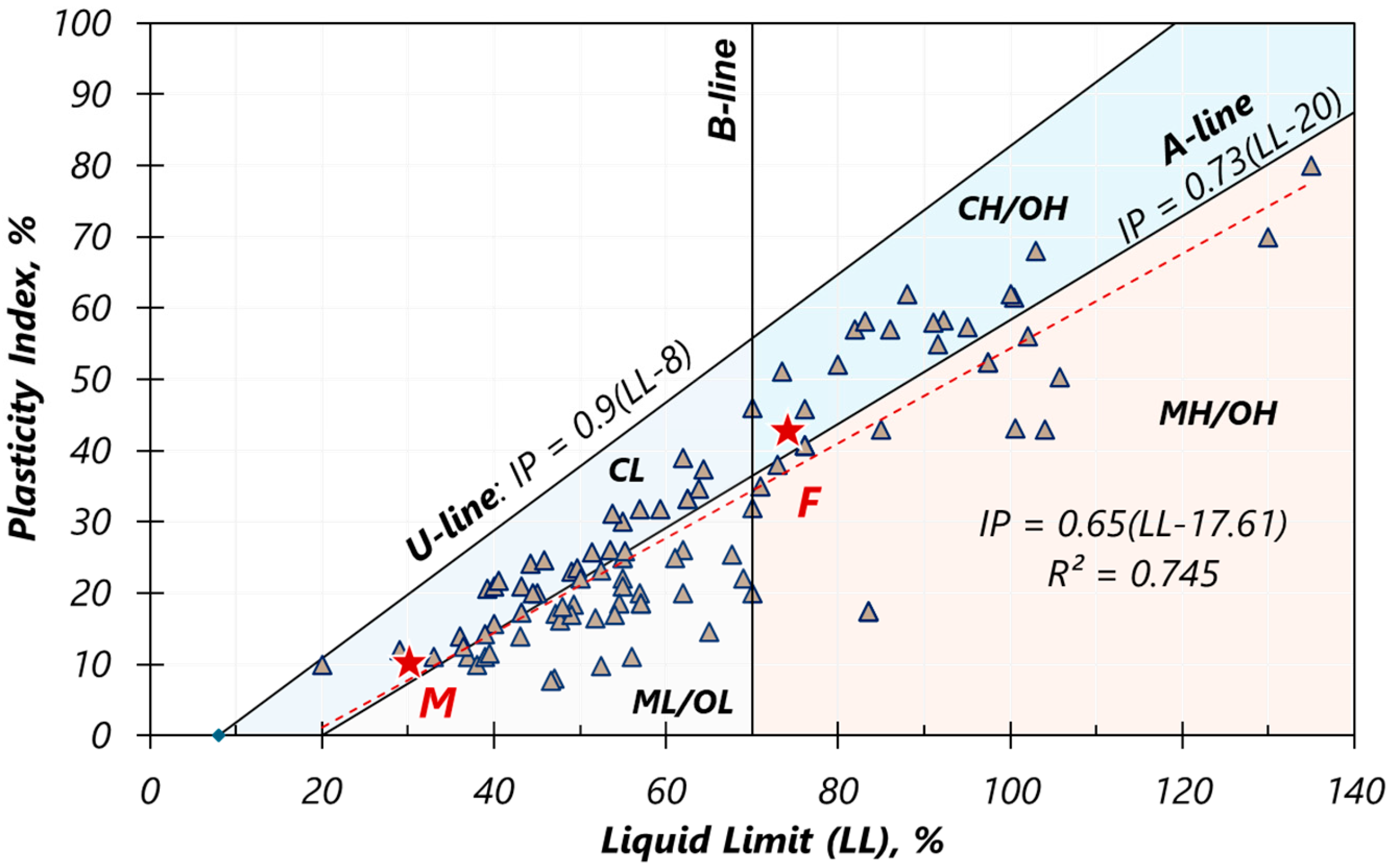
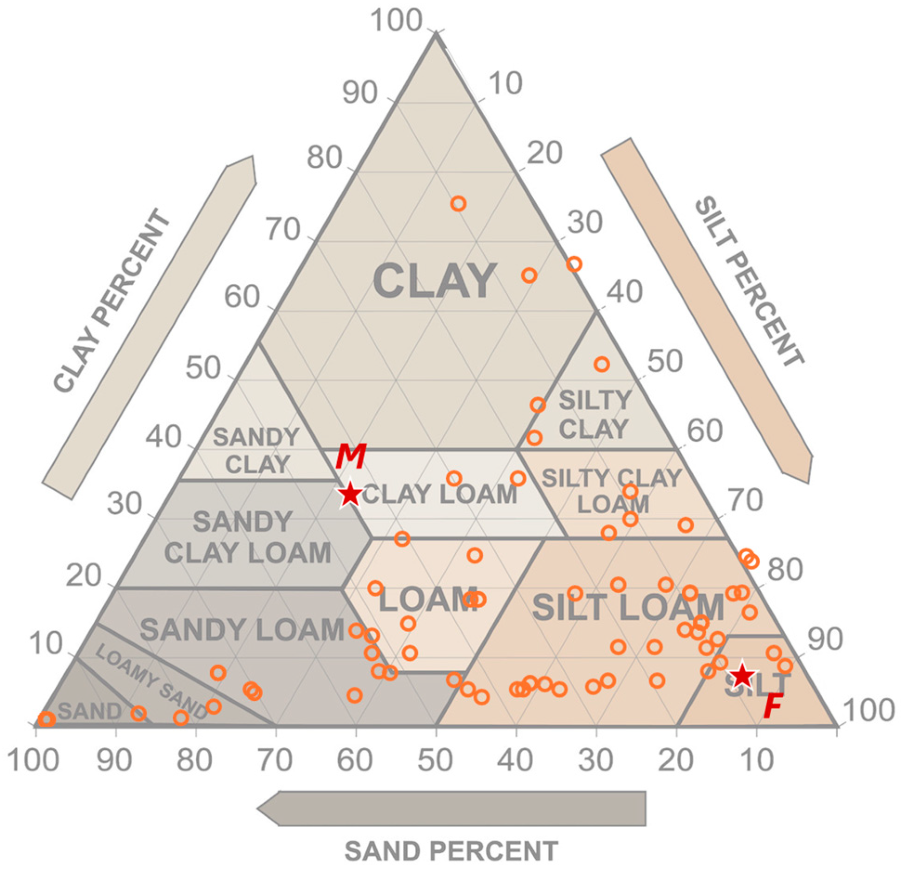
Table 1, alongside Figure 3 and Figure 4, contrasts the key index properties of the two DS and immediately explains why their geotechnical behavior—and ultimately their response to binder treatment—diverge so sharply.
DS-M was recovered as a true fluid mud: Its natural water content (≈256%) is more than ten times that of DS-F (15.9%), placing it well above its LL (76%). In the field, such a slurry cannot be compacted until it is at least partially de-watered or blended with drier borrow material. The grain-size distribution reinforces this assessment: 80% of DS-M particles are finer than 80 µm, whereas DS-F contains only 17% fines and is therefore amenable to immediate mechanical compaction. Organic matter loss on ignition corroborates the textural picture. With 17.1% OM, DS-M falls into the organic silt domain; humic acids and fulvates present at this level are known to consume Ca(OH)2 and retard the formation of cementitious hydrates, thereby raising the “lime-fixation point” [96] and prolonging setting times. DS-F, by contrast, contains just 1.5% OM—low enough that binder hydration proceeds unhindered. Both materials exhibit moderate methylene-blue values (MBV ≈ 2 g/100 g), but the engineering meaning of that number changes once fine content is considered. For DS-M, the combination of high MBV plus very high fines signals a large specific surface area and strong water affinity; for DS-F, the same MBV is diluted by a sand matrix and thus reflects only modest clay activity. The lower specific gravity of DS-M (2.35 g/cm3) is likewise consistent with its elevated organic fraction and saline precipitates, and it limits the maximum dry unit weight that can be achieved even under optimal compaction. Plasticity parameters complete the picture: DS-M displays a LL of 76% and a PI of 41%, classifying it as a CH/MH soil with very high compressibility and shrink–swell potential; DS-F, with LL = 30% and PI = 10%, plots firmly in the low-plasticity ML zone. According to the GTR guide, the raw DS-M is designated subclass A1hF12 and must be pretreated before any earthwork, whereas DS-F is subclass B5 and can be rendered roadworthy with conventional lime–cement stabilization.
In summary, DS-F satisfies—or is close to—the four empirical thresholds that predict economic stabilization (MBV < 3 g/100 g; PI < 25%; OM < 7 wt.%; fines < 35%). DS-M fails three of these four criteria, explaining why the modest 3% lime + 6% cement dosage was insufficient to raise its IBI above 8%. The data therefore illustrate the practical value of these screening limits: they flag, at desk-study stage, which dredged lots can enter a direct soil–cement workflow and which require higher-energy valorization routes.

3.2. Sample Preparation and Compaction Testing

To improve the sediment’s properties, a commercial lime–cement blend HRB was used (ROLAC®645), formulated for soil stabilization. Based on preliminary trials (binder dosage of 2% to 10%), binder dosages of 6% and 8% by dry weight (wt.%) were adopted for this study. These rates were chosen to represent a moderate and a somewhat higher stabilization level, within typical ranges for soil improvement projects (5–10%). For comparison, untreated sediment (0% binder) was also tested. Prior to mixing, the dried sediments were cooled to ambient temperature and their moisture content adjusted. The binder was added to the sediments and mixed thoroughly for several minutes until a uniform mixture was obtained. After an initial mellowing period (~10 min), the mixture was deemed ready for compaction or specimen preparation. For DS-M, a lime–cement blend (3 wt.% quicklime + 6 wt.% CEM I 52.5) was selected in accordance with the French NF P 98-114-3 protocol for highly plastic fines.
A series of laboratory tests were carried out to evaluate both the immediate bearing capacity and the longer-term mechanical strength of the raw and treated sediments. Table 2 summarizes the experimental testing. First, Modified Proctor compaction tests were performed to determine the optimum water content (OWC) and maximum dry density (MDD) for each formulation (0%, 6%, and 8% binder). For each mixture, several specimens were compacted at varying moisture contents around the expected optimum. After compaction, the wet density of each specimen was calculated, then converted to dry density knowing the moisture content.
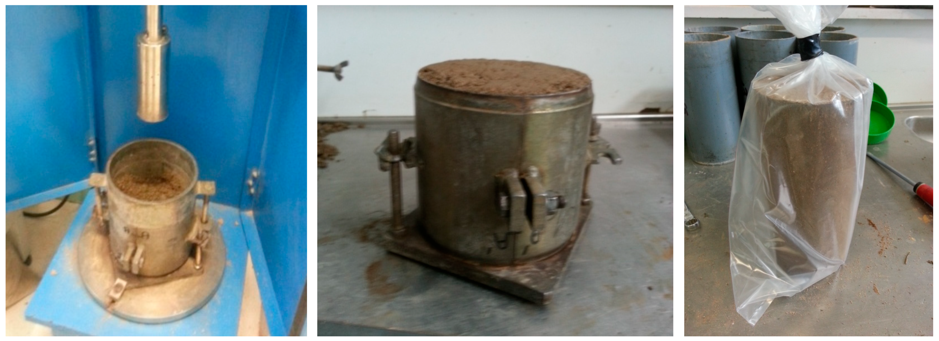
Immediately following each Proctor compaction, an IBI test was conducted on the same specimen (in the Proctor mold) according to NF P94-078 [97]. The IBI (also known as Immediate CBR) measures the penetration resistance of a standard piston (Ø 50 mm) driven into the compacted soil. Two readings of force are taken at 2.5 mm and 5.0 mm penetration, and the larger of the corresponding indices (scaled relative to standard pressures) is reported as the IBI%. This test simulates the ability of the compacted soil to support construction equipment shortly after compaction. Identical Proctor-IBI campaigns were run on the M-0 and M-LC mixes. Figure 5 presents the preparation of the samples. All immersion curing was carried out in tap water in accordance with NF P 94-100, which specifies potable water for soil–binder specimens.

3.3. Specimen Preparation for Strength Testing

To evaluate the mechanical performance over time, cylindrical specimens of the sediment–binder mixtures were prepared and cured under controlled conditions (Table 2). The material was mixed at its optimum water content for each binder dosage, then compacted using static compression in a mold (NF P98-230-2). The static compaction apparatus slowly presses the material into the mold to achieve a dense, uniform sample. Curing regimes followed French standard recommendations (NF P94-100) to simulate field curing (Table 2). Because the M-LC mix never exceeded IBI = 8%, no cylindrical specimens were produced for UCS/ITS measurements.

3.4. Mechanical Tests and Criteria

UCS tests were performed at ages of 7, 14, 28, 60, and 90 days on triplicate specimens for each mix. UCS (noted Rc) is the peak axial stress attained when loading the cylinder in simple compression at a constant strain rate. This test indicates the material’s load-bearing capacity and is used to judge when the treated layer can support traffic. A UCS ≥ 1.0 MPa at 7- or 28-d is generally deemed sufficient for heavy construction equipment to safely drive on the layer without failure. In this study, the 28-d UCS values for the 6% and 8% binder mixtures were of primary interest (as 28-d is a common reference age for design). Additionally, immersion tests were conducted on some 60-d specimens: a set of samples cured normally for 28-d was subsequently immersed in water at 20 °C for another 32 days before UCS testing at 60-d. The compressive strength of these soaked samples (Rci60) was compared to that of companion samples cured 60 days in air (Rc60). This ratio Rci60/Rc60 evaluates the water resistance of the treated soil. According to criteria, a ratio above 0.8 (for soils with low plasticity like this one) is considered satisfactory (i.e., the material retains at least 80% of its strength upon prolonged saturation).
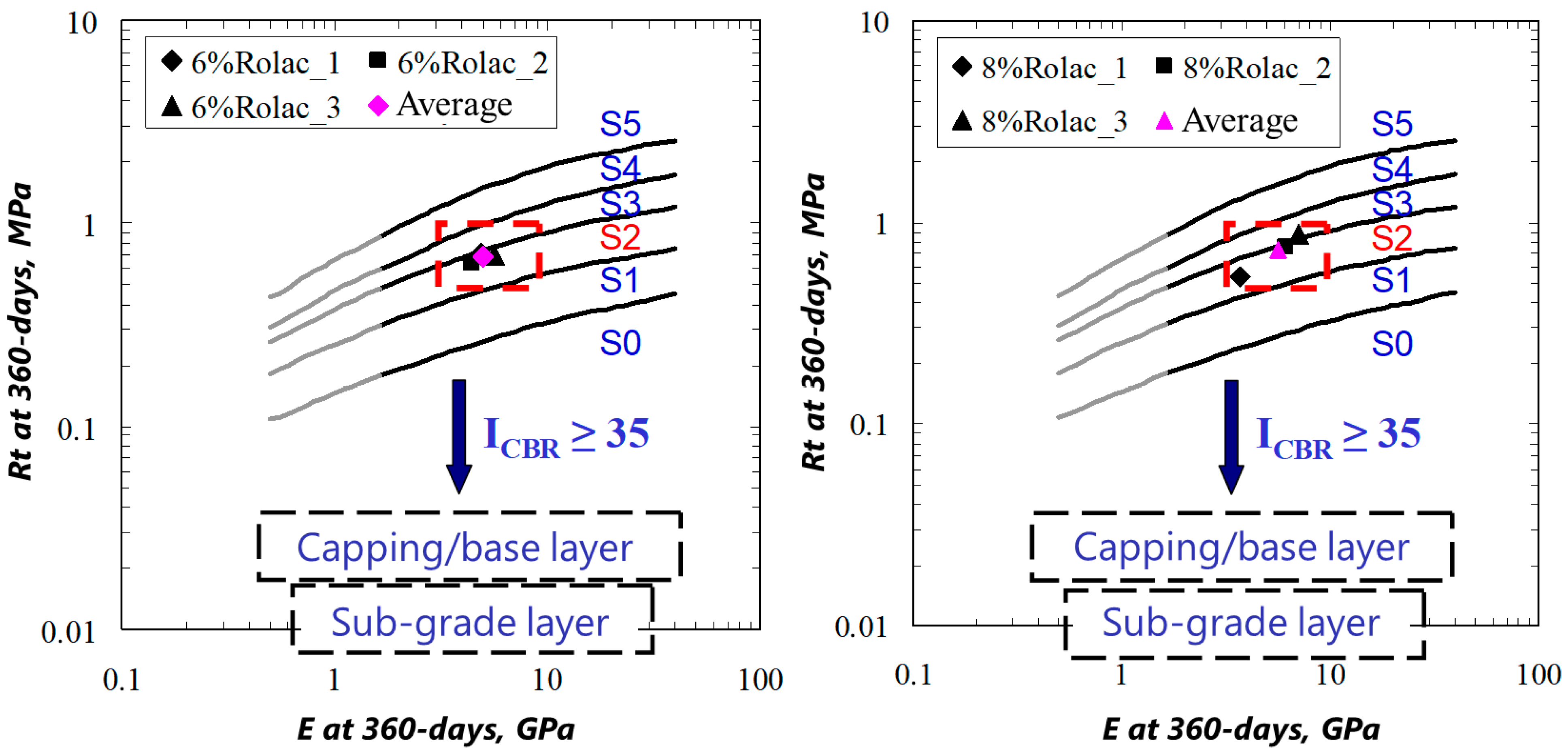
Indirect tensile strength (ITS) tests (also known as Brazilian splitting tests) were performed at 28-d. The ITS Rt is calculated from the peak load. The ITS is an important parameter for long-term performance, as it correlates with the material’s resistance to cracking and fatigue under traffic loads. French design methods classify treated soils into mechanical classes based on 90-d (or 180-d) tensile strength and elastic modulus. In this study, due to time constraints, ITS at 28-d was measured and then projected the 90-d and 360-d values using empirical growth factors from the literature (for similar cement-treated soils). Specifically, factors of E28/E360 and E90/E360 were used to estimate the 360-d elastic modulus, and a similar approach for tensile strength (assuming most gain occurs by 90-d). These estimates allow us to position the material on the standard design classification chart (plot of tensile strength vs. modulus) for road subgrades.
Finally, qualitative frost resistance was considered. The treated soil is deemed frost-resistant if its ITS at the time of the first frost exceeds 0.25 MPa. In many cases, this simply means ensuring a certain curing time before winter; in this case, even at 28-d, the measured tensile strengths were expected to surpass 0.25 MPa, indicating that the material would not be overly susceptible to freeze-thaw damage. (Formal freeze–thaw cycle tests were not conducted in this study due to time limits).

4. Results and Discussion

4.1. Compaction Behavior and Immediate Bearing Capacity

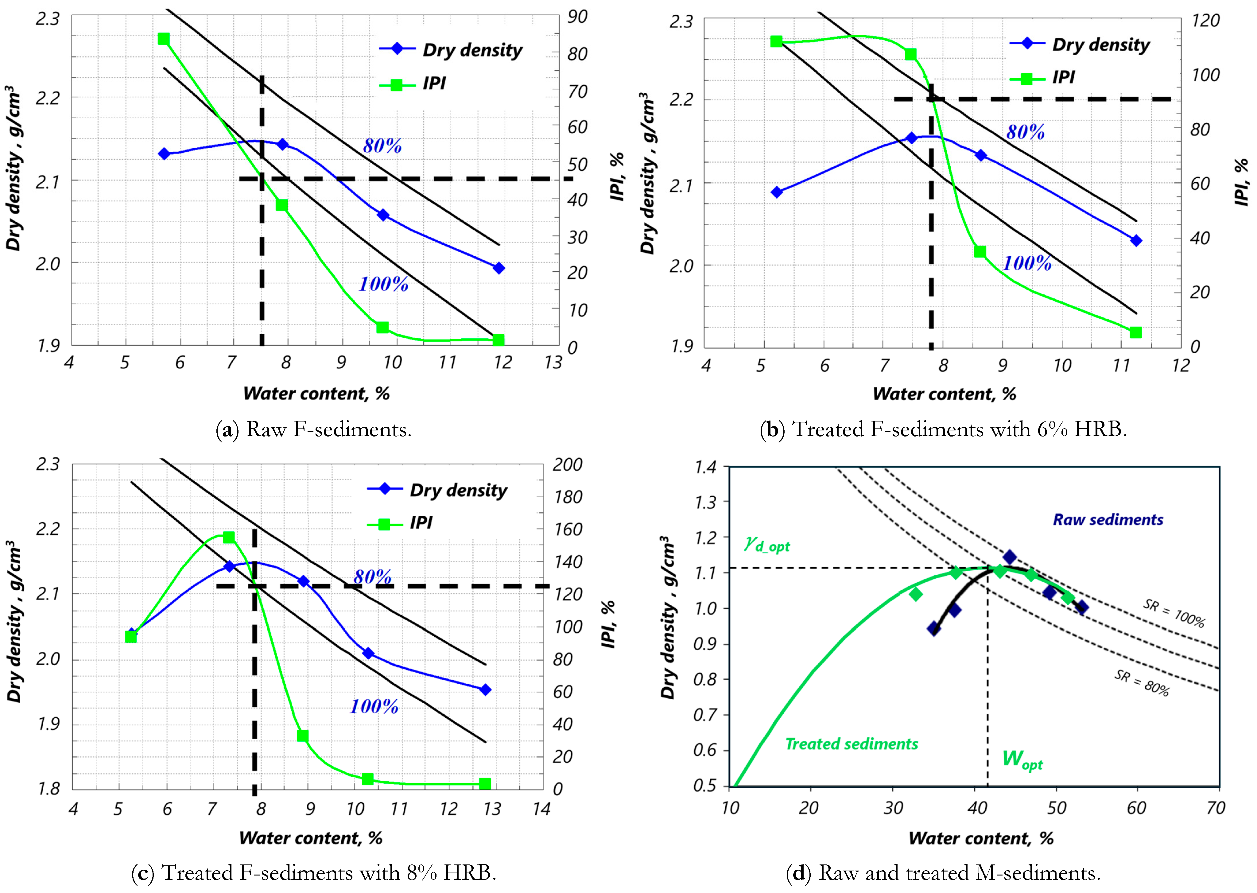
The Proctor test results (Figure 6 and Table 3) demonstrated that the untreated DS-F (F-0) has a relatively high maximum dry density (around 2.15 g/cm3) at a low optimum moisture (~7.5%). This reflects the granular nature of the DS (dominantly sand–silt). The IBI of 45% for F-0, while not extremely low, suggests that, in its compact state, the material is on the borderline of suitability for a foundation layer (which usually requires IBI ≥ 35%). It would not be adequate as a base layer without improvement, since base layers often demand higher bearing ratios (e.g., CBR > 60%). The water sensitivity of the raw DS is also a concern—as a fine-grained material with some silt and clay, if it became wetter than OWC, its strength could drop rapidly.
Because every specimen was compacted at identical Modified Proctor effort, differences in dry density stem solely from water-content variation rather than compactive method. On the dry side of optimum (w < wopt.), the mix remains partly unsaturated; matric suction already provides 10 kPa of apparent cohesion, so adding binder raises IBI only modestly. On the wet side (w > wopt.), suction is negligible, and the untreated soil is weak; the extra water disperses the HRB particles, accelerates C-S-H precipitation, and rapidly bridges pores, giving a much steeper IBI increase even though ρd is slightly lower. This asymmetry—suction-dominated versus hydration-dominated behavior—explains why the “dry” branch of each curve is flatter than the “wet” branch.
Upon the addition of the HRB binder, there were notable changes. The F-6 mixture showed a slight increase in optimum moisture to 7.8% and essentially the same MDD (2.155 g/cm3). The IBI doubled to ~90%, indicating a major gain in early strength. This can be attributed to the formation of cementitious bonds (cement/lime hydration products), which provide cohesion and bonding between particles even before long-term curing. The F-8 mixture had a similar compaction curve (OWC 7.9%, MDD 2.148 g/cm3) and achieved an even higher IBI of ~125%. The fact that an 8% binder yields IBI > 100% (where 100% is roughly equivalent to a well-graded crushed rock based on the CBR scale) is remarkable—it suggests the treated sediment, immediately after compaction, behaves almost like a cement-stabilized granular base. This exceeds typical requirements for subgrade layers by a large margin. In practice, using more binders (8%) provides a greater factor of safety in bearing capacity, which might be beneficial if the material is expected to support construction traffic very soon after treatment or under poor weather. However, from an economic standpoint, the 6% binder already brought the IBI to 90%, well above the needed threshold. The marginal benefit of the extra 2% binder (in terms of IBI) might not justify the extra cost unless particularly high early strength is required. For most applications, achieving IBI ~90% is sufficient for a robust subgrade.
It should be noted that these IBI tests were conducted at optimal moisture content. In the field, if the sediments are wetter than optimal during compaction, the immediate bearing will be lower. One advantage of binder treatment is that it often broadens the workable moisture range—the IBI remains relatively high even if the moisture is a few percentage points above optimum because the binder can consume some water and maintain strength. The compaction curves indicate that at 90% saturation (slightly wet of optimum), the treated soils still had high dry density and likely good bearing. Conversely, if the soil is too dry, compaction is less efficient. In this study, moisture was controlled to near-optimum values for consistency.
The raw DS-M (Figure 6d) exhibits an extremely flat compaction curve with MDD ≈ 1.15 g/cm3 at OWC ≈ 44%. Its IBI is only 5%, confirming that very soft behavior persists even at optimum density. Lime–cement treatment raises IBI to 8% but fails to reach the 25% minimum; maximum dry density even decreases slightly to 1.09 g/cm3, indicating that binder hydration water further dilutes the skeleton.

4.2. Strength Development and Criteria Compliance

UCS results at 28-d highlight the effectiveness of stabilization (Figure 7). No UCS or ITS curves are reported for DS-M because neither the untreated nor the lime–cement mixture met the prerequisite IBI ≥ 25% for strength testing (Appendix A). The untreated DS was too soft to yield a meaningful UCS value (it would likely crumble at very low stress). In contrast, the 6% binder mix (F-6) reached an average UCS of about 4.7 MPa in 28-d (with individual tests ranging from 4.6 to 4.8 MPa). The 8% binder mix (F-8) achieved about 5.9 MPa at 28-d. These strengths are on par with or higher than typical cement-treated soils (for instance, a clay soil stabilized with 4–5% cement might reach 1–2 MPa at 28-d; here, DS are sandy silt with higher binder content, yielding >4 MPa). Notably, both mixes easily exceed the 1.0 MPa threshold needed for trafficability. In fact, even at 7-d, the UCS of F-6 and F-8 already surpassed 1 MPa (values at 7-d and 14-d were around 1.5–3 MPa, increasing with time). This indicates that a treated layer could be open to construction traffic within one week of stabilization, satisfying project scheduling needs.
The effect of curing time was apparent: strengths climbed between 7- and 28-d as hydration progressed. Beyond 28-d, further increases were observed at 60- and 90-d, though at a slower rate (e.g., UCS at 90-d for F-8 was in the range of 7–8 MPa). These gains align with the continued formation of cement hydration products (C–S–H, ettringite, etc.), which densify the matrix. The presence of quicklime in the binder also triggers pozzolanic reactions with clay fractions over time, contributing to later strength growth (though the sediment’s clay content is limited).
The immersion tests provided insight into the material’s durability against water. After 60-d, the ratio of Rci60/Rc60 was determined for F-6 and F-8. Both mixes retained well above 80% of their strength upon water immersion, satisfying the insensitivity criterion for low-plasticity soils. In fact, F-6 showed a ~0.85–0.90 ratio and F-8 ~0.95, meaning almost no strength loss from saturation—a testament to the strong cementation bonds formed. This is critical for road applications because subgrades can become saturated (e.g., due to rainfall or high-water tables) and must maintain integrity.
The ITS results at 28-d were similarly encouraging. The average Brazilian tensile strength of F-6 at 28-d was about 0.35–0.40 MPa (after applying the 0.8 factor), whereas F-8 was slightly higher, around 0.45–0.50 MPa. These values exceed the 0.25 MPa frost resistance criterion, implying that even an early-winter frost would not cause cracking in a cured layer of this material. When extrapolated to 90-d and beyond, the ITS might approach ~0.5–0.6 MPa for F-6 and ~0.7 MPa for F-8 at full maturity (360 -days).
Correspondingly, the elastic modulus of the stabilized sediments was measured during the UCS tests (from stress–strain curves in the elastic range). At 28-d, the secant modulus at 50% UCS for F-6 was on the order of 800–1000 MPa, and for F-8, around 1200 MPa. By 90-d, estimated moduli were ~1500 MPa (F-6) and ~2000 MPa (F-8). These stiffness values place the material in a medium- to high-range for treated soils—much stiffer than natural clay or silt subgrades, though not as stiff as cement-treated crushed rock.
Using the 90-d equivalent tensile strength and modulus, the results were located on the LCPC design chart. Both the 6% and 8% mixes fall into the domain of classes 3–4 materials (the exact class depends on the boundary; roughly, F-6 is lower class 3, F-8 upper class 3, or approaching class 4). Since this classification was originally developed for either central plant-mixed or in situ-treated soils, a slight adjustment is made: In situ-treated materials are typically assigned to one class lower than plant-mixed of the same properties (due to expected variability). Even with that, F-6 would be class 2 and F-8 class 3 by in situ standards. In any case, the material meets the requirement for subgrade (≥class 1) and foundation (≥class 2) layers comfortably (see Table 4 for platform classes).
It is evident from the above that 6% binder stabilization was sufficient to satisfy all the technical criteria for using this DS in a road subgrade or even as a capping layer on soft ground. The 8% binder mix provided even higher performance margins. In practical terms, the choice between 6% and 8% would depend on project requirements: If a high-category road (with heavy traffic) is planned and one desired extra rigidity in the platform, 8% might be justified. Otherwise, 6% achieves the necessary outcomes with lower costs. It is also worth noting that excessive binders could lead to more brittle behavior; while the tests did not show any adverse effects at 8%, some studies caution that above a certain binder content, improvements plateau and shrinkage or cracking may increase. The results suggest 6–8% is within the optimal range for this material.
Under the 20 °C humid-air schedule adopted here, DS-F treated with 6% HRB attained UCS = 1.1 MPa and IBI ≈ 65% after just 7-d. French guidelines (LCPC/GTR, 2022) permit construction equipment and controlled site traffic on stabilized layers once UCS ≥ 1 MPa, provided a temporary 0.15 m granular mattress or geogrid is placed to spread tyre contact. Hence, for road-rehabilitation projects, the layer can normally be re-opened to site traffic within 7–10 days, while the full 28-d cure is only required before sealing and handing over to the public. Where even shorter delays are necessary, contractors routinely combine (i) lime pre-treatment to accelerate early stiffening or (ii) fabric-covered steam blankets (35–40 °C) that halve the time to reach 1 MPa in cool weather. These practices keep the proposed stabilization workflow compatible with phased-lane construction and live-traffic management on upgrade sites.

4.3. Comparison with Other Studies and Sustainability Aspects

The performance of the stabilized DS in this study is comparable to or better than results reported for similar materials in the literature. For instance, Wang et al. [40,41] treated Dunkirk harbor sediment with various binders and found UCS in the range of 1–5 MPa and stiffness up to ~1500 MPa, which aligns with the findings. Boutouil (1998) [98] also reported successful solidification of dredged mud into road base materials, though often requiring higher binder ratios for very soft, clay-rich sludges. The advantage in this case is the sediment’s moderate fine content and low organics, which make it inherently more responsive to solidification/stabilization.
Importantly, the reuse of this material in road construction would yield environmental benefits. Instead of transporting ~2 tons/m3 of DS to landfill (and possibly importing the same amount of quarry fill), the material can be processed on or near the site and returned to use on the road. This cuts down on waste and preserves natural aggregate resources. If scaled up, such practice contributes to the circular economy of construction materials. Economically, using DS can reduce material costs—Yoobanpot et al. [20] found a 1.5× cost advantage in Thailand, and while exact figures differ, savings can be expected, especially if disposal costs are high. There may also be indirect savings from avoiding social and environmental costs of dumping.
One must consider potential challenges as well. Contaminants in marine DS (e.g., heavy metals, hydrocarbons) need evaluation; stabilization can immobilize some contaminants, but leachate testing (e.g., per EN 12457) is recommended to ensure the material is environmentally sound for open use. In this case, the DS came from a relatively clean maintenance dredging (low OM content); oily odors or discoloration that might indicate contamination were not observed, and binder additions generally reduce leaching of metals by stabilization in the cementitious matrices. However, a full environmental characterization would be prudent before field implementation.
Furthermore, field pilot studies would be useful to confirm that the laboratory performance translates to in situ conditions. Factors like curing in colder temperatures, field mixing efficiency, and traffic loading over time should be verified. The laboratory curing at 20 °C and even the accelerated curing are idealized conditions. In situ, the gain of strength might be slower; thus, conservative curing periods (e.g., wait 2–3 weeks before heavy trafficking) might be applied in practice for safety.
Overall, this study’s results support the feasibility of recovering DS as a construction material. Not only does the stabilized DS meet the necessary criteria, but it does so with moderate binder content and conventional techniques. This implies that many ports or coastal projects could adopt similar methods to reduce the footprint of dredging operations. The concept aligns well with sustainable infrastructure development, transforming a dredging by-product into a useful input for roads and thereby closing a resource loop.

4.4. Field Realism, Economics and Constructability

  • Uniformity. Laboratory mixing yields near-perfect binder dispersion; field re-mixers are less efficient. The SETRA guide therefore applies a 0.8 in situ factor to lab UCS. For the 6% HRB mix (UCS at 28-d ≈ 4.7 MPa), the “design UCS” is 3.8 MPa—still above the 1 MPa trafficability threshold. Three UCS cores per 1000 m2 after 7-days are recommended to confirm compliance.
  • Cost-optimization. Material pricing (2025 French averages: HRB = 170 EUR/t, DS handling = 11 EUR/m3) shows that raising the dose from 6% to 8% increases layer cost by 18 EUR/m3 yet boosts IBI only from 90% to 125%. Designers should therefore select the lowest dose that clears LCPC Class S2 (IBI ≥ 80%, UCS ≥ 3 MPa) with a 10% margin.
  • Pavement response. Mechanistic–empirical analysis indicates that a subgrade modulus of 900 MPa under a 2800 MPa unbound base yields vertical surface deflection < 350 µm and IRI < 2.3 m/km after 20 years—well within French PF 3 limits. Ride comfort is therefore not jeopardized.
  • Site processing. Two French pilots processed 60,000 m3 and 85,000 m3 of DS by windrowing for 7–10 days (to w ≈ 15%) followed by trommel-screening (<20 mm) at ≈4000 m3/day. All-in processing cost was 2.3 EUR/m3, confirming feasibility for medium- to large-scale road-platform works.

5. Conclusions

This research demonstrated that DS can be effectively stabilized for reuse as a road subgrade material. The DS, initially classified as a silty soil of GTR subclass B5, had marginal bearing capacity in its natural state but responded very well to treatment with a lime–cement hydraulic binder. Key findings and conclusions include:
  • DS-M—despite 3% lime + 6% cement—remained far below the IBI threshold (max = 8%), demonstrating that highly plastic, organic-rich dredging falls outside the cost-effective application window for direct soil–cement stabilization.
  • Binder stabilization greatly enhanced the sediment’s properties: A 6–8% addition of road binder roughly doubled to tripled the IBI (from ~45% to >120%) and produced UCS above 4–5 MPa at 28-d. ITS also increased to ~0.4–0.5 MPa. These improvements satisfy all criteria for use in roadbed layers (subgrade or capping layers), including trafficability, water resistance, and frost durability.
  • The optimum binder content appears to be around 6%, balancing performance and economy. While an 8% binder yielded higher strength and IBI, the incremental benefit may not be necessary for typical subgrade applications. Even at 6%, the treated DS achieved mechanical class S2, meaning it can serve for foundation layers supporting pavements. The material can be classified as a PF3 platform when properly compacted to ~30 cm thickness, depending on the underlying soil support.
  • Comparison with standards and other studies confirms the validity of the approach. The treated DS meets French roadway standards (LCPC-SETRA) and is in line with international findings on soil–binder mixtures. It underscores that dredged fines can be turned into a construction asset with standard stabilization techniques. Minor variations in mix design (e.g., inclusion of FA or slag) could further optimize performance or cost if needed.
  • Sustainability impact: Reusing this DS in road construction would divert a substantial quantity of material from waste disposal. It reduces the demand for virgin borrow soils and the environmental disturbances associated with their extraction. Moreover, if the project site is near the dredging location, it cuts down on haulage distance, lowering carbon emissions. The successful application here advocates for the broader adoption of dredge material recycling in coastal regions.
  • Future considerations: Prior to field implementation, it is recommended to perform leaching tests to ensure that any contaminants in the DS are securely immobilized by the binder (meeting environmental regulations for reuse). Additionally, a field pilot section would be valuable to monitor the in situ compaction, curing, and performance under actual weather and loading conditions. Long-term monitoring would confirm the durability of the stabilized layer, especially through seasonal cycles.
In conclusion, this study provides a practical example of sustainable material management: challenging waste (marine DS) was transformed into a high-quality engineering material through stabilization. The approach supports both infrastructure development and environmental protection goals. With appropriate precautions and design, DS can be safely and effectively used in road construction, opening the door to more eco-friendly and circular practices in the construction industry.

Author Contributions

Conceptualization, A.Z.; methodology, A.Z.; validation, N.-E.A., S.P. and M.K.; formal analysis, A.Z.; investigation, A.Z.; resources, N.-E.A.; data curation, A.Z.; writing—original draft preparation, A.Z.; writing—review and editing, N.-E.A. and A.e.M.S.; visualization, A.Z. and A.e.M.S.; supervision, N.-E.A., S.P., and M.K.; project administration, N.-E.A., S.P., and M.K.; funding acquisition, N.-E.A., S.P., and M.K. All authors have read and agreed to the published version of the manuscript.

Funding

Safhi A. acknowledges the funds received via the EU-H2023 MSCA (101155413, UP-RISE). The authors’ views and opinions are their own and do not represent those of the European Union or its affiliated institutions.

Institutional Review Board Statement

Not applicable.

Informed Consent Statement

Not applicable.

Data Availability Statement

The original contributions presented in this study are included in the article. Further inquiries can be directed to the corresponding author.

Conflicts of Interest

The authors declare no conflicts of interest.

Appendix A. Failure Mechanisms for DS-M

The lime–cement blend (3 wt.% CaO + 6 wt.% CEM I) improved DS-M’s IBI only marginally (5% to 8%), leaving it far below the 25–35% threshold for road platforms. Four coupled mechanisms account for this failure:
  • High OM inhibition. DS-M contains 17 wt.% OM—more than twice the 7 wt.% limit above which lime fixation is notoriously difficult [46,85]. Humic and fulvic acids preferentially consume Ca(OH)2, preventing an early pH rise and delaying reactions. A stoichiometric estimate (0.8 g CaO per gram of organic carbon) indicates that ≈9 wt.% lime would be needed merely to neutralize the organic acids, three times the dose used here.
  • Excessive clay activity and surface area. Although its (MBV = 2.4 g/100 g) appears moderate, 80% of particles are finer than 80 µm. Converting MBV to specific surface (~50 m2/g) yields a binder-to-surface ratio of only 0.15 g binder m−2, compared with 0.46 g/m2 for DS-F. The limited Ca2+ supply could not satisfy the cation-exchange demand, so flocculation and particle bonding remained weak.
  • Dilutive w/b ratio. Even at the optimum moisture (≈44%), the paste w/b ratio exceeded 3.5. Hydration products thus formed as isolated nodules that did not percolate into a continuous skeleton, leaving the DS’s original structure essentially intact.
  • Low attainable dry density. The organic fraction lowers the specific gravity, capping the maximum dry density despite Modified-Proctor energy. The resulting loose matrix collapses readily under penetration, explaining the persistently low IBI.
Empirical dosage charts in NF P 98-114-3 predict that a clay-rich soil with PI > 35 and fines >70% would require 12–15 wt.% HRB or preliminary mechanical dewatering to achieve platform-class bearing. Hence, DS-M lies outside the economic window for direct soil–cement reuse and should instead be routed to higher-energy valorization pathways.

References

  1. Safhi, A.e.M.; Rivard, P.; Yahia, A.; Benzerzour, M.; Khayat, K.H. Valorization of Dredged Sediments in Self-Consolidating Concrete: Fresh, Hardened, and Microstructural Properties. J. Clean. Prod. 2020, 263, 121472. [Google Scholar] [CrossRef]
  2. Amar, M.; Benzerzour, M.; Kleib, J.; Abriak, N.-E. From Dredged Sediment to Supplementary Cementitious Material: Characterization, Treatment, and Reuse. Int. J. Sediment Res. 2021, 36, 92–109. [Google Scholar] [CrossRef]
  3. Safhi, A.e.M.; Mejjad, N.; El FadilI, H.; Bortali, M. Dredged Materials in Morocco: Current Practices, Policies, and Roadmap for Sustainable Management. Case Stud. Constr. Mater. 2024, 20, e03045. [Google Scholar] [CrossRef]
  4. Dorleon, G.; Rigaud, S.; Techer, I. Management of Dredged Marine Sediments in Southern France: Main Keys to Large-Scale Beneficial Re-Use. Environ. Sci. Pollut. Res. 2024, 1–24. [Google Scholar] [CrossRef] [PubMed]
  5. Crocetti, P.; González-Camejo, J.; Li, K.; Foglia, A.; Eusebi, A.L.; Fatone, F. An Overview of Operations and Processes for Circular Management of Dredged Sediments. Waste Manag. 2022, 146, 20–35. [Google Scholar] [CrossRef] [PubMed]
  6. Casper, S.T. Regulatory Frameworks for Sediment Management. In Sustainable Management of Sediment Resources; Sediment Management at the River Basin Scale; Owens, P.N., Ed.; Elsevier: Amsterdam, The Netherlands, 2008; Volume 4, pp. 55–81. [Google Scholar]
  7. Wang, Y.-S.; Lim, J.-Y.; Lim, S.; Lee, B.-S.; Lin, R.; Wang, X.-Y. Alternative Application of Wollastonite in Limestone Calcined Hwangtoh Clay Cement (LC3) Systems: Engineering Properties, Microanalysis and Resistance to Sulfuric Acid Attack. Constr. Build. Mater. 2025, 475, 141214. [Google Scholar] [CrossRef]
  8. Wang, Y.-S.; Meng, L.-Y.; Chen, L.; Wang, X.-Y. An Innovative Strategy for CO2 Conversion and Utilization: Semi-Wet Carbonation Pretreatment of Wollastonite to Prepare Carbon-Fixing Products and Produce LC3. Cem. Concr. Compos. 2025, 160, 106050. [Google Scholar] [CrossRef]
  9. Ma, J.; Sun, J.; Yu, Z.; Hou, G.; Xia, B. A Comprehensive Review of Dredged Marine Sediments -Multiple Roles of Utilization in Cement-Based Materials and Construction Products. Mar. Pollut. Bull. 2025, 217, 118079. [Google Scholar] [CrossRef]
  10. Safhi, A.E.M. Dredged Materials as Construction Resource—Up-to-Date Review. In Valorization of Dredged Sediments as Sustainable Construction Resources; CRC Press: Boca Raton, FL, USA, 2022; ISBN 978-1-00-331555-1. [Google Scholar]
  11. Bouchikhi, A.; Safhi, A.e.M.; Rivard, P.; Snellings, R.; Abriak, N.-E. Fluvial Sediments as SCMs: Characterization, Pozzolanic Performance, and Optimization of Equivalent Binder. J. Mater. Civ. Eng. 2022, 34, 04021430. [Google Scholar] [CrossRef]
  12. Bouchikhi, A.; Amar, M.; Arroug, L.; Safhi, A.e.M.; Haddaji, Y. Characterizing Nano-Indentation and Microstructural Properties of Mine Tailings-Based Geopolymers. Case Stud. Constr. Mater. 2024, 21, e03899. [Google Scholar] [CrossRef]
  13. Bouzar, B.; Mamindy-Pajany, Y.; Hurel, C. Innovative Reuse of Fly Ashes for Treatment of a Contaminated River Sediment: Synthesis of Layered Double Hydroxides (LDH) and Chemical Performance Assessments. Waste Biomass Valorization 2023, 14, 3923–3945. [Google Scholar] [CrossRef]
  14. Wan, X.; Ding, J.; Mou, C.; Wang, J.; Zhang, S. Alkali-Activated Red Mud in Stabilizing Marine Dredged Clay with Low Amount of Cement. Eur. J. Environ. Civ. Eng. 2023, 27, 4598–4612. [Google Scholar] [CrossRef]
  15. Chompoorat, T.; Thanawong, K.; Likitlersuang, S. Swell-Shrink Behaviour of Cement with Fly Ash-Stabilised Lakebed Sediment. Bull. Eng. Geol. Environ. 2021, 80, 2617–2628. [Google Scholar] [CrossRef]
  16. Chompoorat, T.; Likitlersuang, S.; Thepumong, T.; Tanapalungkorn, W.; Jamsawang, P.; Jongpradist, P. Solidification of Sediments Deposited in Reservoirs with Cement and Fly Ash for Road Construction. Int. J. Geosynth. Ground Eng. 2021, 7, 85. [Google Scholar] [CrossRef]
  17. Chompoorat, T.; Thepumong, T.; Taesinlapachai, S.; Likitlersuang, S. Repurposing of Stabilised Dredged Lakebed Sediment in Road Base Construction. J. Soils Sediments 2021, 21, 2719–2730. [Google Scholar] [CrossRef]
  18. Zentar, R.; Wang, H.; Wang, D. Comparative Study of Stabilization/Solidification of Dredged Sediments with Ordinary Portland Cement and Calcium Sulfo-Aluminate Cement in the Framework of Valorization in Road Construction Material. Constr. Build. Mater. 2021, 279, 122447. [Google Scholar] [CrossRef]
  19. Bazne, M.O.A.; Howard, I.L.; Vahedifard, F. Stabilized Very High–Moisture Dredged Soil: Relative Behavior of Portland-Limestone Cement and Ordinary Portland Cement. J. Mater. Civ. Eng. 2017, 29, 04017110. [Google Scholar] [CrossRef]
  20. Yoobanpot, N.; Jamsawang, P.; Poorahong, H.; Jongpradist, P.; Likitlersuang, S. Multiscale Laboratory Investigation of the Mechanical and Microstructural Properties of Dredged Sediments Stabilized with Cement and Fly Ash. Eng. Geol. 2020, 267, 105491. [Google Scholar] [CrossRef]
  21. Brahim, M.; Ndiaye, K.; Aggoun, S.; Maherzi, W. Valorization of Dredged Sediments in Manufacturing Compressed Earth Blocks Stabilized by Alkali-Activated Fly Ash Binder. Buildings 2022, 12, 419. [Google Scholar] [CrossRef]
  22. Wang, D.X.; Abriak, N.E.; Zentar, R.; Xu, W. Solidification/Stabilization of Dredged Marine Sediments for Road Construction. Environ. Technol. 2012, 33, 95–101. [Google Scholar] [CrossRef]
  23. Wareham, D.G.; Mackechnie, J.R. Solidification of New Zealand Harbor Sediments Using Cementitious Materials. J. Mater. Civ. Eng. 2006, 18, 311–315. [Google Scholar] [CrossRef]
  24. Segui, P.; Safhi, A.e.M.; Amrani, M.; Benzaazoua, M. Mining Wastes as Road Construction Material: A Review. Minerals 2023, 13, 90. [Google Scholar] [CrossRef]
  25. Safhi, A.E.M. (Ed.) Valorization of Dredged Sediments as Sustainable Construction Resources; CRC Press: Boca Raton, FL, USA, 2022; ISBN 978-1-00-331555-1. [Google Scholar]
  26. AFNOR NF P94-050 ; Sols: Reconnaissance et Essais–Détermination de La Teneur En Eau Pondérale Des Matériaux–Méthode Par Étuvage. Afnor Editions: La Plaine Saint-Denis, France, 1995.
  27. AFNOR XP P94-041; Soil: Investigation and Testing. Granulometric Description. Wet Sieving Method. Afnor Editions: La Plaine Saint-Denis, France, 1995.
  28. AFNOR XP P94-047; Soils: Investigation and Testing. Determination of the Organic Matter Content. Ignition Method. Afnor Editions: La Plaine Saint-Denis, France, 1998.
  29. AFNOR NF P94-068; Soils:Investigation and Testing. Measuring of the Methylene Blue Adsorption Capacity of à Rocky Soil. Determination of the Methylene Blue of à Soil by Means of the Stain Test. Afnor Editions: La Plaine Saint-Denis, France, 1998.
  30. AFNOR NF EN ISO 17892-3; Geotechnical Investigation and Testing—Laboratory Testing of Soil—Part 3: Determination of Particle Density. Afnor Editions: La Plaine Saint-Denis, France, 2015.
  31. ISO 17892-12; Geotechnical Investigation and Testing—Laboratory Testing of Soil—Part 12: Determination of Liquid and Plastic Limits. ISO: Geneva, Switzerland, 2018.
  32. Zhang, C.L.; Liu, Q.S.; Liu, J.B. Field Plate Load Tests on Dredged Sediment Dump Pond with Cement Solidified Crust Above. Adv. Mater. Res. 2011, 255–260, 2751–2755. [Google Scholar] [CrossRef]
  33. He, X.; Chen, Y.; Wan, Y.; Liu, L.; Xue, Q. Effect of Curing Stress on Compression Behavior of Cement-Treated Dredged Sediment. Int. J. Geomech. 2020, 20, 04020204. [Google Scholar] [CrossRef]
  34. Zentar, R.; Dubois, V.; Abriak, N.E. Mechanical Behaviour and Environmental Impacts of a Test Road Built with Marine Dredged Sediments. Resour. Conserv. Recycl. 2008, 52, 947–954. [Google Scholar] [CrossRef]
  35. Dubois, V.; Abriak, N.E.; Zentar, R.; Ballivy, G. The Use of Marine Sediments as a Pavement Base Material. Waste Manag. 2009, 29, 774–782. [Google Scholar] [CrossRef]
  36. Zentar, R.; Abriak, N.-E.; Dubois, V.; Miraoui, M. Beneficial Use of Dredged Sediments in Public Works. Environ. Technol. 2009, 30, 841–847. [Google Scholar] [CrossRef]
  37. Bourabah, M.A.; Abou-Bekr, N.; Taibi, S. Geotechnical Characterization of Dredging Sediments for Valorization in Road Embankments: Case of the Cheurfas Dam (Algeria). In Proceedings of the GeoFlorida 2010, American Society of Civil Engineers, Orlando, FL, USA, 15 February 2010; pp. 2212–2221. [Google Scholar]
  38. Miraoui, M.; Zentar, R.; Abriak, N.-E. Road Material Basis in Dredged Sediment and Basic Oxygen Furnace Steel Slag. Constr. Build. Mater. 2012, 30, 309–319. [Google Scholar] [CrossRef]
  39. Zentar, R.; Wang, D.; Abriak, N.E.; Benzerzour, M.; Chen, W. Utilization of Siliceous–Aluminous Fly Ash and Cement for Solidification of Marine Sediments. Constr. Build. Mater. 2012, 35, 856–863. [Google Scholar] [CrossRef]
  40. Wang, D.; Abriak, N.E.; Zentar, R. Strength and Deformation Properties of Dunkirk Marine Sediments Solidified with Cement, Lime and Fly Ash. Eng. Geol. 2013, 166, 90–99. [Google Scholar] [CrossRef]
  41. Wang, D.; Abriak, N.E.; Zentar, R. Co-Valorisation of Dunkirk Dredged Sediments and Siliceous–Aluminous Fly Ash Using Lime. Road Mater. Pavement Des. 2013, 14, 415–431. [Google Scholar] [CrossRef]
  42. Tang, I.Y.; Yan, D.Y.S.; Lo, I.M.C.; Liu, T. Pulverized Fuel Ash Solidification/Stabilization of Waste: Comparison between Beneficial Reuse of Contaminated Marine Mud and Sediment. J. Environ. Eng. Landsc. Manag. 2015, 23, 202–210. [Google Scholar] [CrossRef]
  43. Le Guern, M.; Dang, T.A.; Boutouil, M. Implementation and Experimental Monitoring of a Subgrade Road Layer Based on Treated Marine Sediments. J. Soils Sediments 2017, 17, 1815–1822. [Google Scholar] [CrossRef]
  44. Kasmi, A.; Abriak, N.-E.; Benzerzour, M.; Azrar, H. Environmental Impact and Mechanical Behavior Study of Experimental Road Made with River Sediments: Recycling of River Sediments in Road Construction. J. Mater. Cycles Waste Manag. 2017, 19, 1405–1414. [Google Scholar] [CrossRef]
  45. Maherzi, W.; Benzerzour, M.; Mamindy-Pajany, Y.; van Veen, E.; Boutouil, M.; Abriak, N.E. Beneficial Reuse of Brest-Harbor (France)-Dredged Sediment as Alternative Material in Road Building: Laboratory Investigations. Environ. Technol. 2018, 39, 566–580. [Google Scholar] [CrossRef]
  46. Serbah, B.; Abou-Bekr, N.; Bouchemella, S.; Eid, J.; Taibi, S. Dredged Sediments Valorisation in Compressed Earth Blocks: Suction and Water Content Effect on Their Mechanical Properties. Constr. Build. Mater. 2018, 158, 503–515. [Google Scholar] [CrossRef]
  47. Hamouche, F.; Zentar, R. Effects of Organic Matter on Mechanical Properties of Dredged Sediments for Beneficial Use in Road Construction. Environ. Technol. 2020, 41, 296–308. [Google Scholar] [CrossRef]
  48. Ho, T.-O.; Tsang, D.C.W.; Chen, W.-B.; Yin, J.-H. Evaluating the Environmental Impact of Contaminated Sediment Column Stabilized by Deep Cement Mixing. Chemosphere 2020, 261, 127755. [Google Scholar] [CrossRef]
  49. Furlan, A.P.; Razakamanantsoa, A.; Ranaivomanana, H.; Amiri, O.; Levacher, D.; Deneele, D. Effect of Fly Ash on Microstructural and Resistance Characteristics of Dredged Sediment Stabilized with Lime and Cement. Constr. Build. Mater. 2021, 272, 121637. [Google Scholar] [CrossRef]
  50. Mkahal, Z.; Mamindy-Pajany, Y.; Maherzii, W.; Abriak, N.-E. Recycling of Mineral Solid Wastes in Backfill Road Materials: Technical and Environmental Investigations. Waste Biomass Valorization 2021, 13, 667–687. [Google Scholar] [CrossRef]
  51. Slama, A.B.; Feki, N.; Levacher, D.; Zairi, M. Valorization of Harbor Dredged Sediment Activated with Blast Furnace Slag in Road Layers. Int. J. Sediment Res. 2021, 36, 127–135. [Google Scholar] [CrossRef]
  52. Tsuchida, T.; Porbaha, A.; Yamane, N. Development of a Geomaterial from Dredged Bay Mud. J. Mater. Civ. Eng. 2001, 13, 152–160. [Google Scholar] [CrossRef]
  53. Salehi, M.; Sivakugan, N. Effects of Lime-Clay Modification on the Consolidation Behavior of the Dredged Mud. J. Waterw. Port Coast. Ocean Eng. 2009, 135, 251–258. [Google Scholar] [CrossRef]
  54. Saussaye, L.; van Veen, E.; Rollinson, G.; Boutouil, M.; Andersen, J.; Coggan, J. Geotechnical and Mineralogical Characterisations of Marine-Dredged Sediments before and after Stabilisation to Optimise Their Use as a Road Material. Environ. Technol. 2017, 38, 3034–3046. [Google Scholar] [CrossRef]
  55. Wang, D.; Zentar, R.; Abriak, N.E. Temperature-Accelerated Strength Development in Stabilized Marine Soils as Road Construction Materials. J. Mater. Civ. Eng. 2017, 29, 04016281. [Google Scholar] [CrossRef]
  56. Maher, A.; Bennert, T.; Jafari, F.; Douglas, W.S.; Gucunski, N. Geotechnical Properties of Stabilized Dredged Material from New York-New Jersey Harbor. Transp. Res. Rec. 2004, 1874, 86–96. [Google Scholar] [CrossRef]
  57. Wang, D.X.; Wang, H.X.; Chen, W.Z. Reinforcement Mechanism of Cement/Lime-Fly Ash Treated Sediments as Road Construction Materials. Appl. Mech. Mater. 2011, 99–100, 924–927. [Google Scholar] [CrossRef]
  58. Zoubir, W.; Harichane, K.; Ghrici, M. Effect of Lime and Natural Pozzolana on Dredged Sludge Engineering Properties. Electron. J. Geotech. Eng. 2013, 18 C, 589–600. [Google Scholar]
  59. Azhar, A.; Chan, C.M. Strength Development in Cement Admixed Fine-Grained Dredged Marine Soils. Appl. Mech. Mater. 2015, 802, 272–276. [Google Scholar] [CrossRef]
  60. Larouci, A.; Yassine, S.; Laïd, L.; Amar, B. Improvement of the Mechanical Performance of Fergoug Dam Sediments Treated for Reuse in Road Engineering. MATEC Web Conf. 2018, 149, 01031. [Google Scholar] [CrossRef]
  61. Jamsawang, P.; Charoensil, S.; Namjan, T.; Jongpradist, P.; Likitlersuang, S. Mechanical and Microstructural Properties of Dredged Sediments Treated with Cement and Fly Ash for Use as Road Materials. Road Mater. Pavement Des. 2020, 22, 2498–2522. [Google Scholar] [CrossRef]
  62. Poorahong, H.; Wongvatana, N.; Jamsawang, P.; Lueprasert, K.; Tantayopin, K.; Chen, X.B. Unconfined Compressive and Splitting Tensile Strength of Dredged Sediments Stabilized with Cement and Fly Ash. Key Eng. Mater. 2020, 856, 367–375. [Google Scholar] [CrossRef]
  63. Larouci, A.; Senhadji, Y.; Laoufi, L.; Benazzouk, A. Valorisation of Natural Waste: Dam Sludge for Road Construction. NEPT 2020, 19, 1075–1083. [Google Scholar] [CrossRef]
  64. Gueffaf, N.; Rabehi, B.; Boumchedda, K. Recycling Dam Sediments for the Elaboration of Stabilized Blocks. Int. J. Eng. Res. Afr. 2020, 50, 131–144. [Google Scholar] [CrossRef]
  65. Cheng, X.; Chen, Y.; Chen, G.; Li, B. Characterization and Prediction for the Strength Development of Cement Stabilized Dredged Sediment. Mar. Georesources Geotechnol. 2021, 39, 1015–1024. [Google Scholar] [CrossRef]
  66. Lang, L.; Chen, B.; Li, D. Effect of Nano-Modification and Fiber-Reinforcement on Mechanical Behavior of Cement-Stabilized Dredged Sediment. Mar. Georesources Geotechnol. 2021, 40, 1–17. [Google Scholar] [CrossRef]
  67. Zhou, Y.; Cai, G.; Cheeseman, C.; Li, J.; Poon, C.S. Sewage Sludge Ash-Incorporated Stabilisation/Solidification for Recycling and Remediation of Marine Sediments. J. Environ. Manag. 2022, 301, 113877. [Google Scholar] [CrossRef]
  68. Grubb, D.G.; Malasavage, N.E.; Smith, C.J.; Chrysochoou, M. Stabilized Dredged Material. II: Geomechanical Behavior. J. Geotech. Geoenviron. Eng. 2010, 136, 1025–1036. [Google Scholar] [CrossRef]
  69. Kim, Y.T.; Ahn, J.; Han, W.J.; Gabr, M.A. Experimental Evaluation of Strength Characteristics of Stabilized Dredged Soil. J. Mater. Civ. Eng. 2010, 22, 539–544. [Google Scholar] [CrossRef]
  70. Kasmi, A.; Abriak, N.-E.; Benzerzour, M.; Azrar, H. Effect of Dewatering by the Addition of Flocculation Aid on Treated River Sediments for Valorization in Road Construction. Waste Biomass Valorization 2017, 8, 585–597. [Google Scholar] [CrossRef]
  71. Yu, H.; Yin, J.; Soleimanbeigi, A.; Likos, W.J. Effects of Curing Time and Fly Ash Content on Properties of Stabilized Dredged Material. J. Mater. Civ. Eng. 2017, 29, 04017199. [Google Scholar] [CrossRef]
  72. Zelleg, M.; Said, I.; Missaoui, A.; Lafhaj, Z.; Hamdi, E. Dredged Marine Sediment as Raw Material in Civil Engineering Applications. In Proceedings of the Contemporary Issues in Geoenvironmental Engineering, Sharm El Sheikh, Egypt, 15–19 July 2017; Singh, D.N., Galaa, A., Eds.; Springer International Publishing: Cham, Switzerland, 2018; pp. 407–418. [Google Scholar]
  73. Zelleg, M.; Said, I.; Hamdi, E.; Lafhaj, Z. Experimental Testing for Zarzis Port Sediments (Tunisia) in Road Materials. Geotech. Res. 2018, 5, 13–21. [Google Scholar] [CrossRef]
  74. Mohammad, S.; Akram, W.; Mirza, S.A. Geotechnical Characterization of Dredged Material and Effect of Lime Stabilisation on Its Strength Characteristics. Appl. Mech. Mater. 2018, 877, 289–293. [Google Scholar] [CrossRef]
  75. Smith, B.T.; Howard, I.L.; Vahedifard, F. Lightly Cemented Dredged Sediments for Sustainable Reuse. Environ. Geotech. 2018, 5, 324–335. [Google Scholar] [CrossRef]
  76. Nguyen, T.T.M.; Rabbanifar, S.; Brake, N.A.; Qian, Q.; Kibodeaux, K.; Crochet, H.E.; Oruji, S.; Whitt, R.; Farrow, J.; Belaire, B.; et al. Stabilization of Silty Clayey Dredged Material. J. Mater. Civ. Eng. 2018, 30, 04018199. [Google Scholar] [CrossRef]
  77. Lei, H.; Xu, Y.; Li, X.; Zheng, G.; Liu, G. Effects of Polyacrylamide on the Consolidation Behavior of Dredged Clay. J. Mater. Civ. Eng. 2018, 30, 04018022. [Google Scholar] [CrossRef]
  78. Huang, H.; Burns, S.E.; Kurtis, K.E. Beneficial Use of Savannah River Dredged Material in Large-Scale Geotechnical Applications. Jpn. Geotech. Soc. Spec. Publ. 2021, 9, 245–248. [Google Scholar] [CrossRef]
  79. Houlihan, M.; Bilgen, G.; Dayioglu, A.Y.; Aydilek, A.H. Geoenvironmental Evaluation of RCA-Stabilized Dredged Marine Sediments as Embankment Material. J. Mater. Civ. Eng. 2021, 33, 04020435. [Google Scholar] [CrossRef]
  80. Lang, L.; Chen, B. Stabilization of Dredged Sediment Using Activated Binary Cement Incorporating Nanoparticles. J. Mater. Civ. Eng. 2022, 34, 04021381. [Google Scholar] [CrossRef]
  81. Khayat, K.H.; Assaad, J.; Daczko, J. Comparison of Field-Oriented Test Methods to Assess Dynamic Stability of Self-Consolidating Concrete. Munic. J. 2004, 101, 13066. [Google Scholar] [CrossRef]
  82. Wang, D.; Xiao, J.; Gao, X. Strength Gain and Microstructure of Carbonated Reactive MgO-Fly Ash Solidified Sludge from East Lake, China. Eng. Geol. 2019, 251, 37–47. [Google Scholar] [CrossRef]
  83. El-Shinawi, A.; Kramarenko, V. Assessment of Stabilized Dredged Sediments Using Portland Cement for Geotechnical Engineering Applications along Hurghada Coast, Red Sea, Egypt. Asian J. Appl. Sci. 2015, 3, 819–830. [Google Scholar]
  84. Kang, G.; Tsuchida, T.; Tang, T.X.; Kalim, T.P. Consistency Measurement of Cement-Treated Marine Clay Using Fall Cone Test and Casagrande Liquid Limit Test. Soils Found. 2017, 57, 802–814. [Google Scholar] [CrossRef]
  85. Rosman, M.Z.; Chan, C.-M.; Anuar, N.M. Compressibility and Permeability of Solidified Dredged Marine Soils (DMS) with the Addition of Cement and/or Waste Granular Materials (WGM). J. Sci. Technol. 2018, 10, 13–20. [Google Scholar] [CrossRef]
  86. Liu, Y.; Ong, D.E.L.; Oh, E.; Liu, Z.; Hughes, R. Sustainable Cementitious Blends for Strength Enhancement of Dredged Mud in Queensland, Australia. Geotech. Res. 2022, 9, 65–82. [Google Scholar] [CrossRef]
  87. Silitonga, E.; Levacher, D.; Mezazigh, S. Utilization of Fly Ash for Stabilization of Marine Dredged Sediments. Eur. J. Environ. Civ. Eng. 2010, 14, 253–265. [Google Scholar] [CrossRef]
  88. Maherzi, W.; Abdelghani, F.B. Dredged Marine Sediments Geotechnical Characterisation for Their Reuse in Road Construction. Eng. J. 2014, 18, 27–37. [Google Scholar] [CrossRef]
  89. Wang, D.; Abriak, N.E.; Zentar, R. Dredged Marine Sediments Used as Novel Supply of Filling Materials for Road Construction. Mar. Georesources Geotechnol. 2017, 35, 472–480. [Google Scholar] [CrossRef]
  90. Silitonga, E. Experimental Research of Stabilization of Polluted Marine Dredged Sediments by Using Silica Fume. MATEC Web Conf. 2017, 138, 01017. [Google Scholar] [CrossRef]
  91. Fourvel, G.; Vidal-Beaudet, L.; Le Bocq, A.; Brochier, V.; Théry, F.; Landry, D.; Kumarasamy, T.; Cannavo, P. Early Structural Stability of Fine Dam Sediment in Soil Construction. J. Soils Sediments 2018, 18, 2647–2663. [Google Scholar] [CrossRef]
  92. Bellara, S.; Hidjeb, M.; Maherzi, W.; Mezazigh, S.; Senouci, A. Optimization of an Eco-Friendly Hydraulic Road Binders Comprising Clayey Dam Sediments and Ground Granulated Blast-Furnace Slag. Buildings 2021, 11, 443. [Google Scholar] [CrossRef]
  93. Jan, O.; Mir, B. Strength Behaviour of Cement Stabilised Dredged Soil. Int. J. Geosynth. Ground Eng. 2018, 4, 16. [Google Scholar] [CrossRef]
  94. Wang, D.; Zentar, R.; Abriak, N.E. Durability and Swelling of Solidified/Stabilized Dredged Marine Soils with Class-F Fly Ash, Cement, and Lime. J. Mater. Civ. Eng. 2018, 30, 04018013. [Google Scholar] [CrossRef]
  95. Li, J.; Zhou, Y.; Wang, Q.; Xue, Q.; Poon, C.S. Development of a Novel Binder Using Lime and Incinerated Sewage Sludge Ash to Stabilize and Solidify Contaminated Marine Sediments with High Water Content as a Fill Material. J. Mater. Civ. Eng. 2019, 31, 04019245. [Google Scholar] [CrossRef]
  96. Sherwood, P. Soil Stabilization with Cement and Lime; National Academies: Washington, DC, USA, 1993. [Google Scholar]
  97. AFNOR NF P94-078; Sols: Soils: Investigation and Tests. CBR After immersion. Immediate CBR. Immediate Bearing Ratio. Measurement on Sample Compacted in CBR Mould. Afnor Editions: La Plaine Saint-Denis, France, 1997.
  98. Boutouil, M.; Levacher, D. Traitement et Valorisation Des Vases de Dragages Par Solidification/Stabilisation: État de l’art. In Proceedings of the VI Journées Nationales Génie Civil- Génie Côtier, Caen, France, 17–19 May 2000; Editions Paralia: Nantes, France, 2000; pp. 367–375. [Google Scholar]
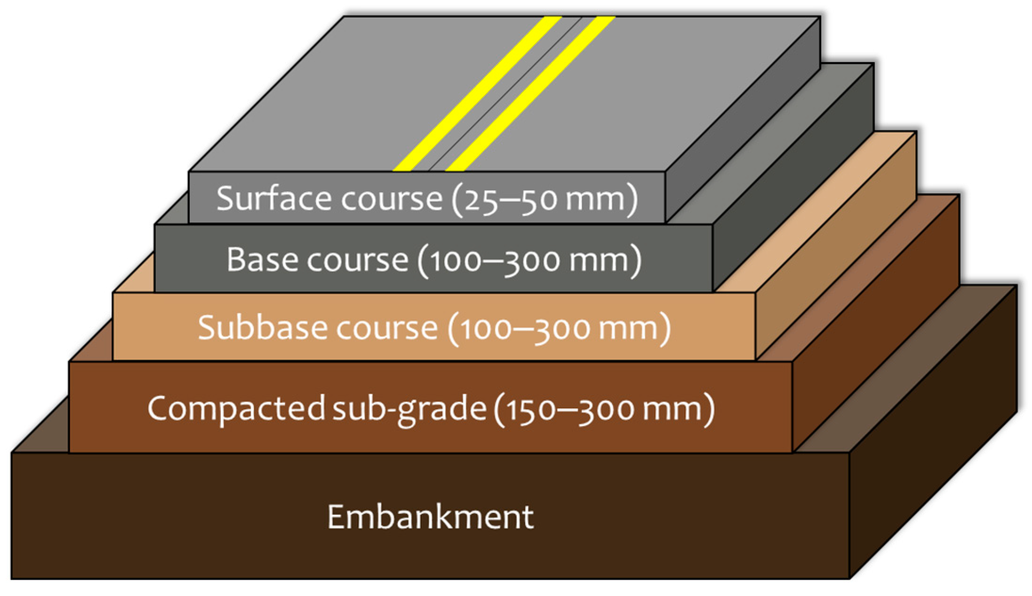
Figure 1. Typical flexible-pavement section showing layer nomenclature and thickness ranges [25].
Buildings 15 02484 g001
Figure 2. From left to right: Material for grinding and sieving dry sediments; grinding the sediments after oven drying using the roller; and sieving the sediments.
Buildings 15 02484 g002
Figure 3. Casagrande plasticity diagram of DS-F and DS-M (red stars), superposed with the results of 98 DS (grey triangles) from 63 papers [16,17,18,19,20,22,23,26,27,28,29,30,31,32,33,34,35,36,37,38,39,40,41,42,43,44,45,46,47,48,49,50,51,52,53,54,55,56,57,58,59,60,61,62,63,64,65,66,67,68,69,70,71,72,73,74,75,76,77,78,79,80,81]. Legend: C: Clay, M: Silt, O: Organic, H: High plasticity, L: Low plasticity. Adapted from Safhi [25].
Buildings 15 02484 g003
Figure 4. Classification of DS-F and DS-M (red stars) superposed with 74 DS (circles) in sand–silt–clay triangular diagram from 44 papers [18,19,22,23,32,33,34,35,36,37,38,39,40,41,42,43,44,45,46,47,48,49,50,51,52,53,54,55,72,73,76,77,81,82,83,84,85,86,87,88,89,90,91,92,93,94,95]. Adapted from Safhi [25].
Buildings 15 02484 g004
Figure 5. From left to right: automatic Proctor-CBR compactor with modified tamper; CBR mold after compaction, removal of the collar and leveling the surface; demolded specimen ready for storing.
Buildings 15 02484 g005
Figure 6. Variation of dry density and IBI with water content for raw and stabilized DS.
Buildings 15 02484 g006
Figure 7. Elastic modulus and traction resistance results at 360 days: left—sediments treated with 6% HRB; right—sediments treated with 8% HRB.
Buildings 15 02484 g007
Table 1. Physical properties and classification of the DS (raw soil).
PropertyStandardDS-MDS-F
Water content (%)NF P94-050 [26]25615.9
Fines < 80 µm (%)XP P94-041 [27]8017
OM at 450 °C (%)XP P94-047 [28]17.11.5
MBV (g/100 g)NF P94–068 [29]2.42.0
Specific gravity (g/cm)ISO 17892-3 [30]2.352.67
LL (%)ISO 17892-12 [31]7630
PI (%)ISO 17892-12 [31]4110
Table 2. Testing matrix and experimental conditions. All specimens were stored double-sealed in plastic film between steps to prevent moisture loss. They were stored in a curing room at 20 ± 2 °C.
TestModified-Proctor Compaction and IBIUCS and Tangent Modulus EBrazilian ITSImmersion Durability Ratio
Mixes/Binder dosage F-0, F-6, and F-8;
M-0, M-LC
F-6, F-8 only (DS-F)F-6, F-8 onlyF-6, F-8
Specimen geometry and preparation152 Ø 126 mm in CBR/Proctor mold; mixed to target moistureCylinders 50 Ø 100 mm; static press compaction to ρdmaxDiscs 50 Ø 50 mm sawn from UCS cylindersSame UCS cylinders
Compaction/mold energy2.7 MJ/m3 (56 blows × 2.5 kg rammer)Static press ≈ 10 MPa
Curing regime before testnone (IBI measured immediately after compaction, sample still in mold)4-d humid air (20 °C, RH > 90%) → 7-d water (40 °C) → humid air (20 °C) until test; additional set 32-d water immersion for 60-d “soaked” UCSSame as UCS (air + water curing)28-d humid air → 32-d water (20 °C)
Test ages (days)07, 14, 28, 60, and 902860
Loading ratePenetration 1.27 mm/minAxial strain ≈ 1%/minDiametral load 0.5 mm/minAxial strain ≈ 1%/min
Replicates (n)3333
Reference standardNF P94-093 (compaction)
NF P94-078 (IBI)
NF P94-251-1 (loading)
NF P94-100 (curing)
NF P98-232-3NF P94-100
Table 3. Proctor testing results.
PropertyStandardDS-MDS-F
F-02.1477.545.3
F-62.1557.890.1
F-82.1487.9124.6
M-01.150445.0
M-LC1.090448.0
Table 4. Comparison of achieved properties with typical requirements for road layers (from LCPC-SETRA guidelines).
CriterionRequirement (Subgrade/Foundation)Achieved (F-6/F-8)
Immediate bearing index (IBI)≥25% (subgrade); ≥35% (foundation)90%/125% (conform)
UCS at 7–28 days≥1.0 MPa (to allow construction traffic)4.7 MPa/5.9 MPa (conform)
Immersion strength ratio 60-d≥0.8~0.9/~0.95 (conform)
Indirect tensile Rt (28 d)≥0.25 MPa (for frost resistance)~0.4/~0.5 MPa (conform)
Class (tensile strength and modulus≥S1 for subgrade; ≥S2 for foundationS2/S2–S3 (conform)
Platform class outcomePF2–PF3 (depending on roadbed support)PF3–PF4 (with 30–40 cm layer)
Disclaimer/Publisher’s Note: The statements, opinions and data contained in all publications are solely those of the individual author(s) and contributor(s) and not of MDPI and/or the editor(s). MDPI and/or the editor(s) disclaim responsibility for any injury to people or property resulting from any ideas, methods, instructions or products referred to in the content.