Abstract
Aiming at the shortcomings of traditional contact cable force monitoring technology in accuracy, efficiency, and applicability, an assessment method based on microwave radar measurements is proposed to measure a sloping cable with a damper for lengths greater than 200 m in this study. A formula for calculating the cable-stayed force with a damper is derived, and an intelligent cable force monitoring platform is developed based on cloud technology. Based on the Chongqing Nanjimen Railway Bridge, a real bridge test was carried out. It was indicated that the microwave radar method could be used to freely adjust the measurement angle and possessed high applicability and penetration. It significantly improved the measurement accuracy and efficiency of cables with a damper for lengths greater than 200 m. It has good application value for the solution of the problems of complicated operation and high costs in the monitoring of cables with a damper. The formula for calculating the cable force with a damper was proven to be reliable and accurate when compared to the results of direct calculation and the equivalent cable length method. It was able to significantly reduce the calculation error of the cable force caused by the influence of the damper. Additionally, the intelligent cable force monitoring platform was utilized to enhance the level of digitization, providing technical support for the scientific management and maintenance of bridges.
1. Introduction
The cable is a vital component of a cable-stayed bridge, as it directly impacts the bridge’s load-bearing capacity, shape, and structural safety [1,2,3]. Accurate measurement of the cable force and its variations is crucial for various purposes, including construction control, health monitoring, safety assessment, and damage diagnosis of cable-stayed bridges [4].
Currently, there are four common methods for cable force monitoring: the tension jack method, pressure sensor method, vibration frequency method, and magnetic flux method [5,6,7]. However, each method has its limitations and advantages. The tension jack method [8,9] is primarily used during the tensioning process, but it cannot provide continuous monitoring of the cable force once a bridge is constructed. The pressure sensor method [10] offers high measurement accuracy and simplicity of operation. However, a pressure sensor needs to be embedded during the cable’s construction stage, and if the sensor is damaged, it cannot be easily replaced. The magnetic flux method [11] has limitations in terms of measurement efficiency and applicability, and it is still in a critical stage of research and development. When using the vibration frequency method [12,13] to measure a cable-stayed cable with a damper, the vibration sensor is more susceptible to the influence of the damper. Thus, a specific operating platform or measurement technique is often required for the accurate identification of the natural vibration frequency of the cable-stayed cable.
Traditional cable force measurement methods have some disadvantages, such as their limited range, low efficiency, insufficient accuracy, and applicability under certain conditions. Therefore, the development of a convenient and efficient cable force measurement method is of great practical significance for the development of long-span bridges. In view of the methods of cable force measurement, scholars have conducted much related research. Jo, Hyeon Cheol et al. [14] proposed a tension and tension range evaluation method based on multiple digital images that was able to obtain the cable force more economically and efficiently than traditional methods could. Xiaofeng Liu et al. [15] proposed a vibration-based elastic–magnetic (VBEM) method that had a good ability to identify the natural frequencies of each order of steel strand. Hongbo Liu [16] conducted dynamic response tests on closed cables and high vanadium cables under prestress and proposed a deep learning model that could intelligently identify the cable force for construction based on test data. Wen-Hwa Wu et al. [17] considered the specific arrangement of the boundary constraints of a suspender of an arch bridge and were able to simply determine the tension of the suspender by concentrating multiple measurements at one end. Marco Bonopera et al. [18] studied the free transverse vibration of a post-reinforced thin-walled steel box girder and found that the dynamic force of the beam largely depended on the contact between the cable and the surrounding section.
There are two common methods for calculating the cable-stayed force with a damper (length ≥ 200 m): the equivalent cable length method and the energy method [19,20,21]. Xiongjun He et al. [19] used the finite-element equivalent cable length instead of the calculated cable length in the traditional vibration frequency method to measure the cable force, which effectively improved the accuracy of the cable force test. Shenghua Tang et al. [20] constructed a formula for calculating the equivalent cable length based on the differential equation of cable vibration and the energy principle. Based on the derivation of cable force formulas under different constraint conditions with the energy method, Xianyu Wang et al. [21] conducted a systematic analysis from three perspectives: the optimization of the cable force at the boom design stage, the measured cable force at the bridge completion stage, and the influence of the cable force on the bending stiffness at the operation stage. Gong Junh [22] took a concrete cable-stayed bridge with a main span containing a 260 m high-speed railway as an example, and they designed the bridge structure according to the functional needs and site conditions; then, they established a three-dimensional finite-element model and adopted the minimum bending energy method and the influence matrix method to determine the reasonable construction state of the cable-stayed bridge. However, the equivalent cable length method only considers the damper as the anchoring section and reduces the length of the cable. It fails to effectively consider the influence of the damper. The energy method only considers the damping of the damper when studying the shape function of the cable, ignoring its stiffness. However, the damper has an equivalent stiffness K that affects the shape function of the cable. This results in an insufficient calculation of the cable force [23,24]. Thus, it is essential to adjust the shape function to align with reality and enhance the accuracy of calculations.
In summary, the field of cable force monitoring with a damper (length ≥ 200 m) presents a significant contradiction. Traditional cable force measurement methods are easily affected by the damper, resulting in low measurement accuracy, efficiency, and applicability. This limitation makes it difficult to meet actual engineering needs. Furthermore, the influence of the damper is not fully considered in the calculation of cable force, which requires improved accuracy. The emergence of big data cloud technology has opened up new opportunities for intelligent monitoring. An intelligent cable force monitoring platform that integrates monitoring, evaluation, and early warning [24] can reduce costs, increase efficiency, and provide technical support for the scientific management and maintenance of bridges.
This study utilizes microwave radar as a tool for detecting the vibration frequency of a cable. The energy method is modified to incorporate the presence of a damper, allowing for the description of the cable’s shape function. Then, a new formula for calculating the cable force with a damper is derived by combining the equivalent stiffness formula of the damper with the modified energy method. The data collected by the microwave radar are then uploaded to an intelligent cable force monitoring platform. The platform automatically processes, analyses, and stores the data, providing cable force monitoring values through the derived calculation formula. An evaluation and early warning system is implemented to assess the cable’s operational status, facilitating intelligent monitoring, evaluation, and early warning of the cable force. This approach provides a scientific basis for ensuring the safe operation of cables.
2. Working Principle
2.1. Microwave Radar Differential Interferometry Technique
Microwave radar differential interferometry [25,26,27,28] is a technique that captures the subtle vibrations of an object at different moments using microwave radar. This technique relies on the characteristics of microwaves, which can be absorbed, reflected, and projected. The phase sum of two observations of an inclined cable is obtained using the differential interferometry technique to determine its deformation over time. A working diagram of microwave radar (Figure 1) and the deformation calculation formula are presented below.
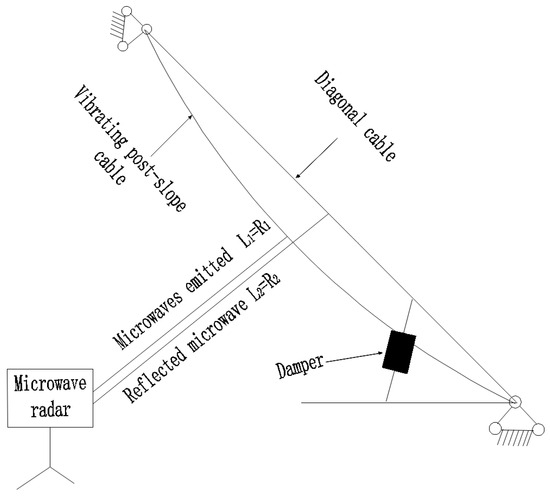
Figure 1.
Schematic diagram of the operation of microwave radar.
The sum of the two observations is used to obtain the phase:
The form variables can be expressed as follows:
2.2. Microwave Radar Frequency Conversion
After the microwave radar collects the time-domain signals of the two vibrations before and after the diagonal cable, the frequency-domain signals are obtained through a Fourier transformation: [29]. can be calculated with Equation (3):
where
—the deformation observation time;
—the frequency resolution, which is inversely proportional.
3. Calculation Formula for a Diagonal Cable with a Damper
3.1. Principle
Firstly, the mode function of the cable is determined, followed by the integration of its kinetic and potential energy over the entire length at a specific time. Then, based on the law of conservation of energy, the relationship between the cable force S and the angular frequency ω is established. Finally, the equation for the relationship between the cable force and frequency is derived by solving and simplifying the equations [30,31,32]. The equivalent stiffness K in the calculation formula can be eliminated by calculating different order frequencies. However, this approach increases the workload of monitoring and calculation. The damper’s information can typically be obtained through design data, field information, or the nameplate. By calculating the equivalent stiffness K based on the known information of the damper, the workload can be significantly reduced, the monitoring efficiency can be improved, and future tests can be facilitated. An equivalent stiffness calculation method was used to modify the existing energy calculation formula given that the damper information was available. It resulted in a more convenient, concise, and efficient formula for calculating cable force with dampers.
3.2. Boundary Conditions
Under the action of dampers, the cable boundary conditions become complicated. According to [33,34,35], the dynamic model was reasonably simplified in this research, and the damper was simplified as the equivalent stiffness K. The cable was connected to the bridge tower and the main beam through an anchor, and its boundary condition was between articulation and consolidation. However, when the cable reached a certain length, the boundary condition of articulation or solid connection had little influence on the calculation of the cable force. Therefore, this study assumes that the cable’s boundary conditions were hinged, so it was assumed that the boundary condition of the cable was articulation.
3.3. Calculation Process
According to [36], the sagging of a cable has little influence on high-order frequencies (4th and above). Therefore, this study took the fourth-order mode as an example for the calculation, without considering the influence of the cable’s dead weight, sagging, and out-of-plane vibration.
When a cable vibrates, the existence of a stagnation point significantly influences the vibration mode of the span with the damper, but it has little influence on the other spans. Consequently, it is assumed that the shape function of the other spans is still a sine function with only one constant difference, and the span with the damper is superimposed with an anti-symmetric higher-order term. Therefore, this study only corrected the calculation of this cross-shape function with the damper, as shown in Figure 2 below.
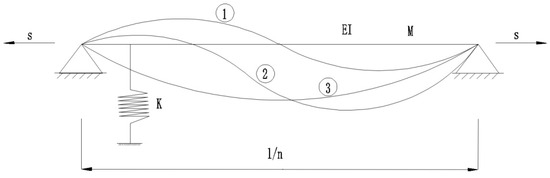
Figure 2.
Shape diagram of the diagonal cable (i = 4).
Here,
The shape function that is superimposed can be expressed as
where
A, B—constants to be determined;
—distance from the damper to the end.
The displacement of points on the diagonal cable at any instant t is described as follows:
The kinetic energy (T) and potential energy (V) of the lasso at any given moment (t) are determined as follows:
According to the law of conservation of energy, the maximum kinetic energy is equal to the maximum potential energy:
Finally, the force of the rope is obtained:
The term in Equation (9) is small and negligible compared to the other terms, so it can be simplified to
Compared with the direct calculation method, the modified energy method includes an additional term () in the calculation formula for the cable force with dampers, which increases the effect of the dampers.
According to the “Technical Regulations for Energy Dissipation and Shock Absorption in Buildings (JGJ297-2013)” [37], the equivalent stiffness K of the damper is calculated based on the parameter information.
where
K—the damper’s equivalent stiffness;
F—the damper’s maximum damping force;
x—the damper’s maximum stroke;
—the yield displacement;
—the post-yield stiffness ratio;
—the initial elastic stiffness of the damper.
By substituting Equations (11) and (12) into Equation (10), we obtain
When the flexural stiffness is disregarded, Equation (14) takes the following form:
3.4. Consideration of the Correction of Bending Stiffness
There is a correlation between the cable force S calculated with Equation (14) and the actual cable force S0, which can be corrected with the correlation coefficient ζ: S0 = ζS. For different cable lengths l, the relationship between the measured cable force and the actual cable force is nonlinear. Therefore, through the nonlinear fitting of the correlation coefficient, the functional relationship between the correlation coefficient ζ and the cable length l can be obtained [5].
4. Evaluation and Early Warning through Cable Monitoring Based on Cloud Technology
An intelligent cable force monitoring platform that integrated monitoring, evaluation, and early warning was established using big data cloud technology [38,39,40,41,42,43,44]. The platform used microwave radar as a sensor to collect cable vibration data, which were then transmitted to the data platform through an interface protocol. After processing and analyzing the data, the cable’s status was evaluated using an objective evaluation and early warning system, and corresponding management measures were provided. The platform comprised the following components and the structure of the intelligent cable force monitoring platform is shown in Figure 3:
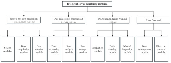
Figure 3.
Schematic structure of the intelligent cable force monitoring platform.
- Sensor and data acquisition and transmission system: First, microwave radar was used to collect the cable vibration data in real time, and then the data were transmitted to the processing, analysis, and storage system through a data acquisition module and data transmission module.
- Data processing, analysis, and storage system: After the data were transmitted to the platform, the calculation formula for the cable force with a damper was used to obtain the monitoring values for professional analysis.
- Evaluation and early warning system: After the monitoring values were obtained, the following evaluation mechanism was established according to the “Technical specification for operation monitoring of urban rail transit facilities Part 2: Bridges (GB/T 39559.2-2020) [S]” [45]:
—the monitoring value of the cable force;
—the corresponding theoretical calculated value of the cable force;
—the discount factor of the theoretical calculated value of the cable force, ∈ [0.95, 1.00].
After the evaluation system, the following determinations were made: (1) The status of the cable was normal according to the routine management; (2) there was a cable status warning, which should be analyzed through research and judgment to put forward solutions, including the need for special inspections, train speed limits, and other recommendations.
- 4.
- User front-end: Instructions were issued and data management functions were performed.
5. Engineering Applications
5.1. Project Overview
The Chongqing Nanjimen Railway Bridge is currently the world’s largest dedicated cable-stayed bridge for railway tracks. Its structural form is that of a five-span high- and low-tower double-cable-plane semi-floating system, and it has a span arrangement of 34.5 m + 180.5 m + 480 m + 215.5 m + 94.5 m. The main beams of the main bridge are all in the form of steel box composite beams, and the bridge tower is in the form of a portal bridge tower. The low bridge tower has a total height of 158 m, while the high bridge tower has a total height of 227 m. The diagonal cable used is a Φ 7.0 mm galvanized high-strength low-relaxation parallel-steel-wire HDPE-sheathed and finished cable, with a tensile strength of not less than 1770 MPa and a tensile elastic modulus of not less than 195,000 MPa. The cable-stayed steel wire is coated with zinc −5% aluminum/mixed rare earth alloy; the steel wire is arranged in a compact concentric twist, and the outermost steel wire is twisted at an angle of 3.5° with respect to the ground with a left turn. The outer layer of the cable is a high-density polyethylene sheath, and a double-helix coil pipe jacket is used to resist wind and rain vibrations. The high tower’s side has 27 pairs of permanent cables—NMC1–NMC27(north mid-span cable) and NSC1–NSC27 (north side-span cable)—while the low tower’s side has 16 pairs of diagonal cables: SSC1–SSC16 (south side-span cable) and SMC1–SMC16 (south mid-span cable). A linear viscous damper with a length greater than 200 m is installed at both ends of the diagonal cables and connected to the main beam. The bridge’s layout is shown in Figure 4, Figure 5, Figure 6, Figure 7, Figure 8 and Figure 9.
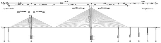
Figure 4.
Layout of the whole bridge (unit: cm).
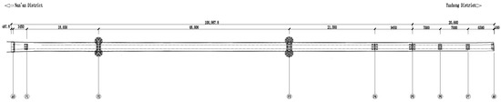
Figure 5.
General layout of the bridge (unit: cm).
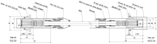
Figure 6.
Diagram of the diagonal cables’ construction.
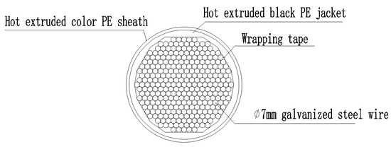
Figure 7.
Cross-sectional drawing of cables.
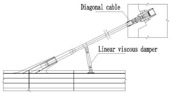
Figure 8.
Schematic diagram of the damper connection.
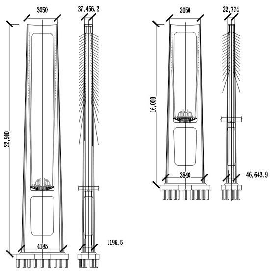
Figure 9.
Cross-sectional view of the main tower (unit: cm).
5.2. Health Monitoring System
5.2.1. System Overview
The long-term health monitoring of the Chongqing Nanjimen Railway Bridge includes load and environmental monitoring, overall static and dynamic response monitoring, and local response monitoring. The overall layout of the health monitoring points of the whole bridge and the sensor information are shown in Figure 10 and Table 1: ①: displacement of the expansion joint; ②: angle of the beam end; ③: video surveillance; ④: vertical deformation of the main beam; ⑤: main beam stress; ⑥: main beam temperature; ⑦: steel structure fatigue; ⑧: horizontal displacement of the pier top; ⑨: main beam vibration (transverse); ⑩: main beam vibration (longitudinal); ⑪: GNSS deformation system; ⑫: ship collision (lateral); ⑬: ship collision (vertical); ⑭: ship collision (longitudinal); ⑮: wind speed and direction; ⑯: temperature and humidity; ⑰: water level; ⑱: cable force monitoring; ⑲: rainfall; ⑳: main tower vibration (transverse); ㉑: main tower vibration (longitudinal); ㉒: main tower stress; ㉓: main tower temperature.
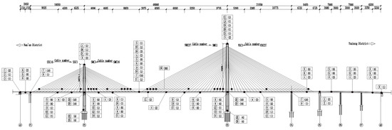
Figure 10.
General layout of the health monitoring points (unit: cm).

Table 1.
Health monitoring equipment information.
5.2.2. Microwave Radar Application
The microwave radar method, vibration frequency method, and pressure sensor method were used to measure SMC1, SMC16, NMC1, and NMC27 of the Chongqing Nanjimen Railway Bridge. The schematic diagrams of the field measurements are shown in Figure 11, and the test data are shown in Figure 12 and Table 2 and Table 3. The deviation rate of the cable force measured with the three test methods—namely, the vibration frequency method, pressure sensor method, and microwave radar method—was equivalent to the deviation ratio of the theoretical cable force: ; here, is the deviation rate of the cable force, S1 is the theoretical cable force, and S2 is the measured cable force.
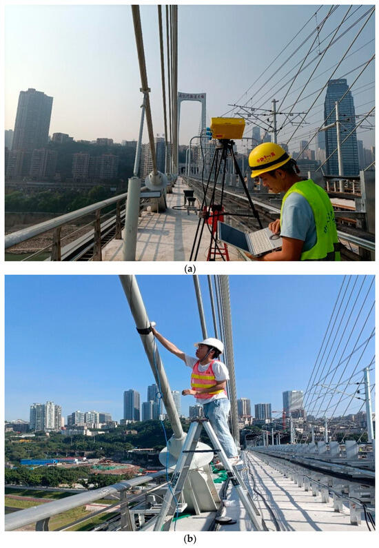
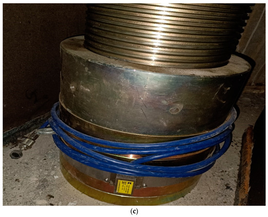
Figure 11.
Schematic diagram of the field measurements. (a) Microwave radar method. (b) Vibration frequency method. (c) Pressure transducer method.
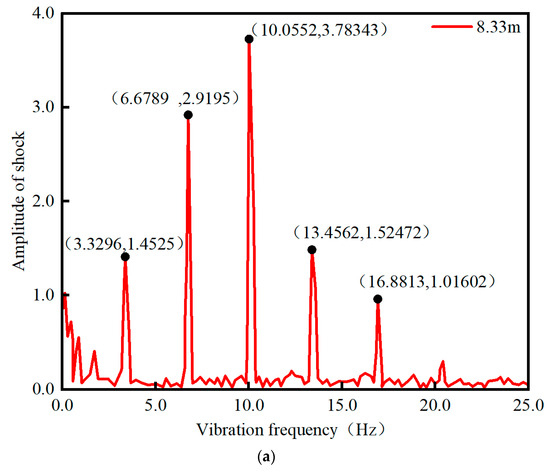
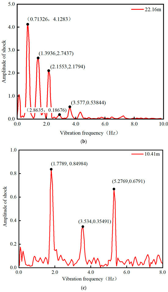
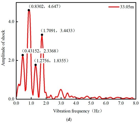
Figure 12.
Spectral diagram of the SMC1, NMC16, NMC1, and NMC27 cables. (a) Base frequency diagram for SMC1. (b) Base frequency diagram for SMC16. (c) Base frequency diagram for NMC1. (d) Base frequency diagram for NMC27.
Table 2.
Measurement results of the vibration frequency method, pressure transducer method, and microwave radar method for an inclined cable with a damper.
Table 3.
Measurement results of the vibration frequency method, pressure sensor method, and microwave radar method for an inclined cable without a damper.
Table 2 demonstrates that for the NMC27 cable with a damper longer than 200 m, the deviation rate of the force measured with microwave radar was only 0.6%. This rate was significantly lower than those of the vibration frequency and pressure sensor methods, indicating that the microwave radar method was highly accurate and reliable. Table 3 shows that the cables without dampers, namely, SMC1, SMC16, and NMC1, which had a length of less than 200 m, had a maximum deviation rate for the cable force of 3.1% when measured using the microwave radar method. This was lower than the deviation rates obtained using the vibration frequency method (6.6%) and the pressure sensor method (8.0%). The results confirmed the excellent applicability of the microwave radar method in meeting the required specifications.
In this study, three methods were applied to measure the cable force of a cable-stayed cable of the Chongqing Nanjimen Railway Bridge. The following were the results: Microwave radar can be used to directly set up freely adjustable equipment, and the cable force measurement can be completed by only two people. The vibration frequency is influenced by the damper, and a ladder needs to be set up. The pressure sensor method is more complex and requires embedding in advance for measurement. These two methods need 3–4 people to complete the work. The vibration frequency method and pressure sensor method do not support multi-target measurement, as only one cable can be measured at a time. In contrast, the microwave radar method can be used to measure the cable force of more than 10 cables simultaneously. This method is based on the principle of non-contact measurement, and it provides better stability and efficiency than contact measurement methods do. Additionally, it can penetrate the HDPE sheath, resulting in more accurate measurement results. Compared to traditional contact measurement methods, the microwave radar method offers significant advantages in terms of measurement accuracy and efficiency for stayed cables with dampers. Table 4 demonstrates that the microwave radar method has significant advantages over traditional contact measurement methods in terms of measurement accuracy and efficiency for an inclined cable with a damper.
Table 4.
Comparison of the advantages and disadvantages of the vibration frequency method, pressure sensor method, and microwave radar method.
5.2.3. GNSS Application
The Chongqing Nanjimen Railway Bridge relies on a GNSS deformation system to monitor the displacement of the main beam and bridge tower. The monitoring items include the transverse, longitudinal, and vertical spatial deformation data of the main beam, as well as the transverse, longitudinal, and vertical spatial deformation data of the top bridge tower. This system provides an important basis for the assessment of the state of the bridge structure. The on-site installation diagram is shown in Figure 13.
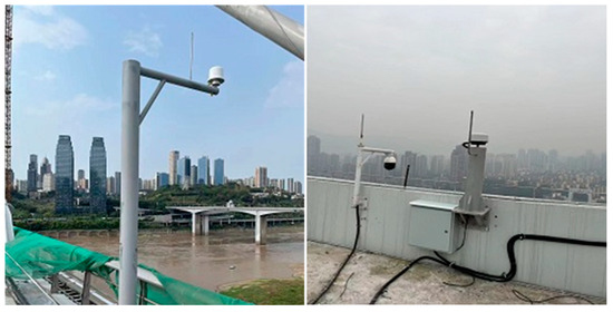
Figure 13.
Photo of the special GNSS antenna used in the field.
Based on the application of the GNSS deformation monitoring system, the maximum vertical deformation, transverse deformation, and longitudinal deformation of the main beam of the Chongqing Nanjimen Railway Bridge were monitored from 1 January 2023 to 31 December 2023. It was found that the deformation of the main beam at the measuring point was not abnormal within the theoretically calculated deformation envelope. The interval of the change in the vertical GNSS deformation of the upper 10 upstream sides of the main beam monitoring section was [−411.4, 88.6], and the amount of change was 500.0 mm.
5.2.4. Application of an Environmental Monitoring System
A temperature and humidity sensor was used to measure the changes in the ambient temperature of the bridge, and the changes in the wind speed and direction at the bridge site were measured with a wind speed and direction instrument, which provided a basis for the analysis of the working environment of the bridge and an evaluation of the driving safety. The ambient temperature measurement points were arranged at the closing section of the main span of the main bridge, and the wind speed and direction measurement points were arranged at the top of tower P3 and the closing section of the main span of the main bridge. The on-site installation diagram is shown in Figure 14 and Figure 15.
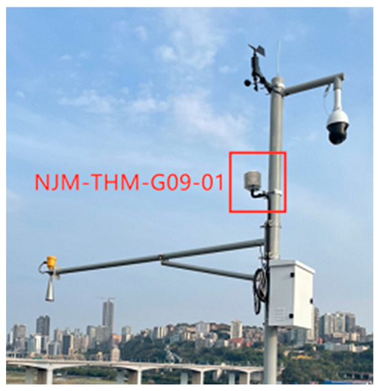
Figure 14.
Photo of the hygrograph site.
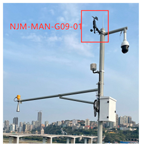
Figure 15.
Field photo of the anemometer.
Based on the ambient temperature monitoring system and the wind speed and direction monitoring system, the temperature and wind speed and direction of Chongqing Nanjimen Railway Bridge were monitored from 1 January 2023 to 31 December 2023. It was found that the maximum wind speed at the measurement point of the middle span of the main bridge was about 17.3 m/s, the daily maximum temperature was 39.3 °C, and the daily minimum temperature was 4 °C.
5.3. Application of the Derived Equation for the Calculation of the Cable Force with Dampers
5.3.1. Error Analysis of the Formula for Calculating the Cable Force of a Cable-Stayed Cable with a Damper
The direct calculation method, the equivalent cable length method, and the derived formula for the calculation of the force of a cable-stayed cable with a damper were used to calculate the force of a cable-stayed cable (NMC16-NM27) of the Chongqing Nanjimen Railway Bridge with a length of over 200 m, as shown in Figure 16; the detailed parameters of the damper are shown in Table 5; the results were analyzed and verified, and they are shown in Table 6.
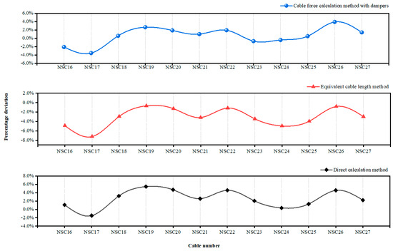
Figure 16.
Comparison of the deviation values of the three calculation methods for the cable force.
Table 5.
Information on the damper parameters.
Table 6.
Comparison of the calculation results of the three methods.
Equation (14) of this paper was used to calculate the cable force of the cable. As shown in Table 6 and Figure 16, for the cable with a damper, the maximum error of the cable force calculated with the direct calculation method with respect to the theoretical cable force was 5.5%, and the total cable force was too large. The maximum error of the equivalent cable length method was −7.2%, and the total calculated cable force value was small, which proved that using the equivalent cable length method to calculate the cable force could not effectively solve the influence of the damper on the cable force. The maximum error of the cable force obtained by using the derived formula of the cable with a damper was 3.9%, which was lower than that of the equivalent cable length method and the direct calculation method. It was proved that the cable calculation formula was effective, and the calculation accuracy was higher than that of the direct calculation method and the equivalent cable length method.
5.3.2. Analysis of the Influence of Bending Stiffness on the Calculation
In this study, Equation (14) was used to calculate the cable force of a cable-stayed cable, and the influence of the bending stiffness was not considered in the calculations. In order to reduce the deviation between the calculated cable force and the measured cable force, the bending stiffness of the 12 cables mentioned above was corrected according to Equation (15) in Section 3.4, and the calculations are shown in Table 7.
Table 7.
Influence of the flexural stiffness of the cable.
After the coefficient correction, it was found that when the cable was long, the influence of the bending stiffness on the accuracy of the measured cable force was almost zero and could be ignored. Therefore, when calculating the cable force of a long and thin cable, the influence of flexural stiffness should not be considered.
5.4. Intelligent Cloud Platform Application
To improve the scientific management of bridges and monitor the operational status of the cable-stayed cables in real time, this study established an intelligent cable force monitoring platform using the Chongqing Nanjimen Railway Bridge as a case study. An evaluation and early warning mechanism was established based on Equations (16) and (17), as shown in Figure 17.
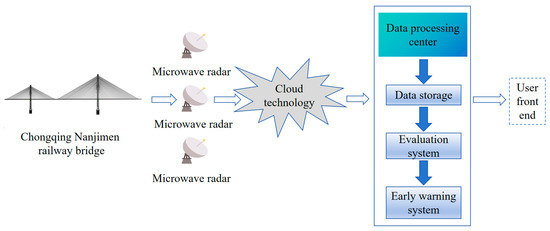
Figure 17.
Schematic diagram of the operation of the intelligent cable monitoring platform.
Figure 17 shows that the use of sensors and data acquisition and transmission systems to collect real-time data in the field can greatly improve the collection efficiency and accuracy and can save labor costs. Then, the data were uploaded to the data processing, analysis, and storage system through cloud technology, analysis, and storage, the complex data were refined, and the cable force monitoring value was obtained after calculation and analysis. Finally, the cable force monitoring value was entered into the evaluation and early warning system. After systemic research and judgment, the real-time operation status of the cable could be presented to the user’s front end simply and clearly. The intelligent cable force monitoring platform had the functions of fine analysis and efficient data processing, which could effectively improve the level of digitization of bridge monitoring and provide technical support for the scientific management of bridges.
6. Conclusions and Prospects
6.1. Conclusions
Relying on the microwave radar method, a derived formula for calculating the cable force with a damper (length ≥ 200 m), and an intelligent cable force monitoring platform for the Chongqing Nanjimen Railway Bridge after a real bridge test, this study obtained the following conclusions:
- Measuring the force of a cable with a damper based on microwave radar is an efficient and reliable method. The actual engineering experiments showed that the deviation rate of the cable force measurements was only 0.6% for a cable with a damper over 200 m in length. At the same time, the measurement angle could be freely adjusted, and the measurement penetration was stronger than that of the traditional method. It was proved that the measurement accuracy, efficiency, and applicability of microwave radar for cable force measurement were superior to those of traditional monitoring methods. This has wide application prospects in the field of cable force monitoring for slender cables with dampers.
- Considering the problem of calculating the cable force of cable-stayed cables with dampers, the presented formula is feasible and can effectively improve the accuracy of the calculation of the cable force. Three calculation methods were used to calculate the force of 12 cable-stayed cables with dampers in the mid-span of the north side of the Chongqing Nanjimen Railway Bridge. The maximum cable force error of the calculation formula for the force of a cable-stayed cable with dampers was only 3.9%, which was lower than 7.1% for the direct calculation method and 5.8% for the equivalent cable length method, which proved that the derived calculation formula was reliable, effective, and accurate. It has reference value in the field of cable force calculation for cable-stayed cables with dampers.
- The intelligent cable monitoring platform integrating monitoring, evaluation, and early warning has the functions of real-time monitoring, real-time analysis, and real-time early warning, and it can provide technical support for the scientific management and maintenance of bridges.
- However, microwave radar is susceptible to electromagnetic interference in the environment, resulting in measurement errors. In the presence of occlusions or space constraints, the measurement accuracy will be reduced. Therefore, it should not be used in an environment with strong electromagnetic interference, occlusions, or space restrictions. The measurement distance and frequency should be paid attention to in the measurement process to ensure the penetration of the signal and the accuracy of the measurement results.
6.2. Prospects
In this study, an assessment method for cable force measurement based on microwave radar and a calculation method for the cable force with a damper were studied to some extent, but there are still the following deficiencies:
- (1)
- The research results in this study showed the achievement of efficient and high-precision measurement of long cables with dampers, but the influence of the cable diameter was not taken into account, and the measurement of short cables with dampers was not studied; further research will be carried out in follow-up work.
- (2)
- The calculation formula for a stayed cable with a damper derived in this study fully considers the influence of the damper, and the calculation results were in line with the expectations, but the influence of the damper was ignored when solving the model. The influence of the damper will be further studied in subsequent work.
Author Contributions
Conceptualization, X.L. and Q.W. (Qin Wang); methodology, P.D.; software, P.D.; validation, X.L., Q.W. (Qin Wang) and P.D.; formal analysis, Q.W. (Qin Wang); investigation, Q.W. (Qin Wang) and X.H.; resources, P.D. and Q.W. (Qin Wang); data curation, P.D. and Q.W. (Qin Wang); writing—original draft preparation, X.H.; writing—review and editing, X.L. and Q.W. (Qin Wang); visualization, X.H.; project administration, X.L.; formal analysis, Q.W. (Qiansong Wang). All authors have read and agreed to the published version of the manuscript.
Funding
This work was supported by the Open Fund of Chongqing Key Laboratory of Energy Engineering Mechanics and Disaster Prevention and Mitigation (EEMDPM2021201) and the Chongqing Institute of Science and Technology Research Grant Program (CKRC2021074 and YKJCX2220644).
Data Availability Statement
All of the data and models that were generated or used during the study are available from the corresponding author by request.
Conflicts of Interest
Author Peng Ding was employed by the company T. Y. Lin International Engineering Consulting (China) Co., Ltd. The remaining authors declare that the research was conducted in the absence of any commercial or financial relationships that could be construed as a potential conflict of interest.
References
- Fang, R.; Wu, Y.; Wei, W.; Na, L.; Biao, Q.; Jiang, P.; Yang, Q. An Improved Static Residual Force Algorithm and Its Application in Cable Damage Identification for Cable-Stayed Bridges. Appl. Sci. 2022, 12, 2945. [Google Scholar] [CrossRef]
- Dai, J.; Qin, F.; Geng, J.; Chen, Y. Review on Cable Force Optimization Method for Cable-staved Bridge in Completed Bridge State. China J. Highw. Transp. 2019, 32, 17–37. [Google Scholar]
- Liu, X.; Yi, X.; Wang, B.; Liu, Y. Condition Assessment of Grouped Cable Forces of Cable-Stayed Bridge Using Deflection Data. Buildings 2023, 13, 472. [Google Scholar] [CrossRef]
- Zhou, Y.; Huang, Z.-H.; Wang, Y.; Xiang, Z.-F.; Zhou, J.-T.; Zhang, X.-S. Measurement Method of Stay Cable Force Based on Measured Cable Shape Using Laser Scanning. China J. Highw. Transp. 2021, 34, 91–103. [Google Scholar]
- Wang, S.-R.; Wang, B.; Cheng, C.-S.; Zhou, J.-T.; Qu, J.-Q.; Tan, H. Research on Influencing Factors of Cable Force Measurement Methods Based on Alignment Recognition. China J. Highw. Transp. 2023, 36, 154–165. [Google Scholar]
- Zhang, L.; Qiu, G.; Chen, Z. Structural health monitoring methods of cables in cable-stayed bridge: A review. Measurement 2021, 168, 108343. [Google Scholar] [CrossRef]
- Zhang, Z.-J.; Wang, R.-H.; Zhen, X.-X.; Liu, X.-H. Evaluation of Measurement Methods for Tension of Parallel Steel Strand Stay Cables. Bridge Constr. 2016, 46, 42–47. [Google Scholar]
- Zhang, R.; Yang, Z.; Zhu, X.; Liang, Q.; Xu, R. Practical Formulas to Calculate Suspender Tension Based on Frequency. J. Southwest Jiaotong Univ. 2015, 50, 823–829. [Google Scholar]
- Li, G.-p.; Li, J.-x. Tension Strategy Derived by Non-stress Length of Parallel Steel Strand Stay Cables. China J. Highw. Transp. 2017, 30, 48–56. [Google Scholar]
- Shen, Q.; Yuan, D.-R.; Chen, C.-X. A New Monitoring Device for the Force States of the Pressure Dispersed Anchor Cable. In Proceedings of the 2015 International Conference on Advanced Engineering Materials and Technology, Guangzhou, China, 22–23 August 2015; pp. 836–841. [Google Scholar]
- Liu, X.; Wu, D.; He, C.; Feng, H.; Wu, B. Comparison of AC and pulsed magnetization-based elasto-magnetic methods for tensile force measurement in steel strand. Measurement 2018, 117, 410–418. [Google Scholar] [CrossRef]
- Ji, B.; Cheng, M.; Fu, Z.; Chen, X.; Sun, Y. Influential factors in cable force measurement of cable-stayed bridges based on vibration frequency method. J. Cent. South Univ. (Sci. Technol.) 2015, 46, 2620–2625. [Google Scholar]
- Fang, Z.; Wang, J.-q. Practical Formula for Cable Tension Estimation by Vibration Method. J. Bridge Eng. 2012, 17, 161–164. [Google Scholar] [CrossRef]
- Jo, H.C.; Kim, S.H.; Lee, J.; Sohn, H.-G.; Lim, Y.M. Sag-based cable tension force evaluation of cable-stayed bridges using multiple digital images. Measurement 2021, 186, 110053. [Google Scholar] [CrossRef]
- Liu, X.; Chen, Y.; Hu, H.; Feng, S.; Feng, Z. Measurement method of natural frequencies and tension forces for cables based on elasto-magnetic sensors calibrated by frequencies. AIP Adv. 2022, 12, 015301. [Google Scholar] [CrossRef]
- Liu, H.; Wang, L.; Guo, L.; Zhang, F.; Chen, Z. Intelligent identification of cable force for short and thick building cables based on deep learning. J. Build. Struct. 2023, 44, 204–213. [Google Scholar]
- Wu, W.-H.; Chen, C.-C.; Chen, Y.-C.; Lai, G.; Huang, C.-M. Tension determination for suspenders of arch bridge based on multiple vibration measurements concentrated at one end. Measurement 2018, 123, 254–269. [Google Scholar] [CrossRef]
- Bonopera, M.; Chang, K.-C.; Tullini, N. Vibration of prestressed beams: Experimental and finite-element analysis of post–tensioned thin-walled box-girders. J. Constr. Steel Res. 2023, 205, 107854. [Google Scholar] [CrossRef]
- He, X.-J.; Yang, Y.-C.; Xiao, X.; Wang, J.-J. A vibration frequency method based on finite element equivalent cable length. Bridge Constr. 2016, 46, 40–44. [Google Scholar]
- Tang, S.-H.; Fang, Z. Equivalent cable length calculation method considering influence of intermediate supports. J. Vib. Shock 2013, 32, 82–87. [Google Scholar]
- Wang, X.; Wang, X.; Liang, X.; Zhou, M.; Du, Y. Analysis of suspension cable force of large-span steel tube concrete tied arch bridge. J. Vib. Shock 2023, 42, 306–313. [Google Scholar]
- Gong, J. Design and research of long-span concrete cable-stayed bridge for high-speed railway. J. Railw. Sci. Eng. 2020, 17, 1611–1619. [Google Scholar]
- Sohaib, M. Study on the Influence of Dampers on Cable-Stayed Bridge Cable Force Estimation. Master’s Thesis, Harbin Institute of Technology, Harbin, China, 2019. [Google Scholar]
- Yang, X. Research on Calculation Method and Influencing Factors of Cable Force of Asymmetric Cable-Stayed Bridge. Master’s Thesis, Lanzhou Jiaotong University, Lanzhou, China, 2020. [Google Scholar]
- Liang, X.; Hui, D.; Zhou, J.; Zhong, J.; Yang, J.; Xiao, Y. Construction and application of health monitoring and evaluation system for long-span cable-stayed Bridges. J. China Foreign Highw. 2016, 36, 92–97. [Google Scholar]
- T/CCTAS 68-2023; Technical Specification for the Detection of Bridge Structure Deformation by millimeter Wave Radar (T/CCTAS 68-2023) Group Standard. China Transportation Association: Beijing, China, 2023.
- Wang, J.; Wang, X.; Zhou, Z. Nano millimeter wave radar for bridge cable tension measurement. J. Natl. Univ. Def. Technol. 2022, 44, 118–122. [Google Scholar]
- Wang, T.; Zhang, J.; Jiang, S.; Liu, W.; Chen, Y. Time-varying cable force identification method based on radar vibration measurement technique. J. Vib. Shock 2023, 42, 205–212. [Google Scholar]
- Liu, Y.; Xie, J.-Z.; Tafsirojjaman, T.; Yue, Q.-R.; Tan, C.; Che, G.-J. CFRP lamella stay-cable and its force measurement based on microwave radar. Case Stud. Constr. Mater. 2022, 16, e00824. [Google Scholar] [CrossRef]
- Xu, W.; Du, D.; Kasai, K.; Wang, S. Optimization layout of viscous dampers and its application in retrofitting of a high-rise steel structure. J. Build. Struct. 2022, 43, 32–44. [Google Scholar]
- Duan, Y.-F.; Huang, J.-S.; Deng, N.; Wang, S.-M.; Ying, Z.-G.; He, W. Vector form intrinsic finite element based simulation on parametric vibration of cables. J. Vib. Eng. 2023, 36, 188–195. [Google Scholar]
- Main, J.A.; Jones, N.P. Vibration of tensioned beams with intermediate damper. II: Damper near a support. J. Eng. Mech. 2007, 133, 379–388. [Google Scholar] [CrossRef]
- Jiang, L.L.; Chen, Q.Z. Research on calculation formula of frequency faso force test. Highway 2018, 63, 164–166. [Google Scholar]
- Dan, D.; Zhao, Y.; Yang, T. Vibration measurement based cable trnsion identifcation method for cable-damper system. J. Vib. Shock 2013, 32, 123–127+204. [Google Scholar]
- Huang, W.; Wu, Q.; Chen, B. Force measurement of stay cable considering damper influence. J. Guangxi Univ. (Nat. Sci. Ed.) 2018, 43, 416–424. [Google Scholar]
- Fang, Z.; Zhang, Z.Y. Test of Cable Tension in Cable-stayed Bridges. China J. Highw. Transp. 1997, 1, 51–58. [Google Scholar]
- JGJ297-2013; Technical Specification for Seismic Energy Dissipation of Buildings. Ministry of Housing and Urban-Rural Development of the People’s Republic of China: Beijing, China, 2013.
- JTG/T3650-01-2022; Technical Regulations for Highway Bridge Construction Monitoring. Ministry of Transport of the People’s Republic of China: Beijing, China, 2022.
- Teng, G.; Cao, X.; Gai, W.; Jiang, R. An Experimental Study on Intelligent Bearing System for Bridge Health Monitoring. In Proceedings of the International Conference on Innovative Solutions in Hydropower Engineering and Civil Engineering, Berlin, Germany, 25–27 December 2022; pp. 319–324. [Google Scholar]
- He, Z.; Li, W.; Salehi, H.; Zhang, H.; Zhou, H.; Jiao, P. Integrated structural health monitoring in bridge engineering. Autom. Constr. 2022, 136, 104168. [Google Scholar] [CrossRef]
- Li, X.; Luo, H.; Ding, P.; Chen, X.; Tan, S. Prediction Study on the Alignment of a Steel-Concrete Composite Beam Track Cable-Stayed Bridge. Buildings 2023, 13, 882. [Google Scholar] [CrossRef]
- Sun, L.-M.; Shang, Z.-Q.; Xia, Y. Development and Prospect of Bridge Structural Health Monitoring in the Context of Big Data. China J. Highw. Transp. 2019, 32, 1–20. [Google Scholar]
- Zhou, Y.; Sun, L. Insights into temperature effects on structural deformation of a cable-stayed bridge based on structural health monitoring. Struct. Health Monit. 2018, 18, 778–791. [Google Scholar] [CrossRef]
- Tong, K.; Zhang, H.; Zhao, R.; Zhou, J.; Ying, H. Investigation of SMFL monitoring technique for evaluating the load-bearing capacity of RC bridges. Eng. Struct. 2023, 293, 116667. [Google Scholar] [CrossRef]
- GB/T 39559.2-2020; Specifications for Operational Monitoring of Urban Rail Transit Facilities—Part 2: Bridge. Ministry of Transport of the People’s Republic of China: Beijing, China, 2021.
Disclaimer/Publisher’s Note: The statements, opinions and data contained in all publications are solely those of the individual author(s) and contributor(s) and not of MDPI and/or the editor(s). MDPI and/or the editor(s) disclaim responsibility for any injury to people or property resulting from any ideas, methods, instructions or products referred to in the content. |
© 2024 by the authors. Licensee MDPI, Basel, Switzerland. This article is an open access article distributed under the terms and conditions of the Creative Commons Attribution (CC BY) license (https://creativecommons.org/licenses/by/4.0/).